forward signaling protocol at the relay nodes is derived. In the analysis ... forward (EF), and selective-relaying (SR). For AF, the ... ply forward the estimation of the received signals to the ..... f(x) g(x). = 0. (30). From this equation, we can see that for a multiple-relay .... [10] H. A. David,âOrder Statisticsâ, John Wiley & Sons Ltd,.
This full text paper was peer reviewed at the direction of IEEE Communications Society subject matter experts for publication in the ICC 2008 proceedings.
Differential Modulation and Selective Combining for Multiple-Relay Networks Li Chu∗ , Jinhong Yuan∗ , Yonghui Li∗∗ & Zhuo Chen∗∗∗ ∗
School of Electrical Engineering and Telecommunications
The University of New South Wales, Sydney, NSW 2052 Australia ∗∗
Telecommunications Group, Department of Electrical Engineering University of Sydney, NSW 2006, Australia
∗∗∗
Wireless Technologies Laboratory, CSIRO ICT Center, Marsfield NSW 2122, Australia
Abstract - In this paper, we consider a multiple-relay network. We propose differential modulation at each communication node and selective combining method at the receiver. As both differential modulation and the selective combining do not require the full channel state information, the system design is greatly simplified without compromising much of the system performance. The average BER for this multiple-relay system with estimation-andforward signaling protocol at the relay nodes is derived. In the analysis, we take into account the effect of imperfect estimation at the relay nodes, by replacing each of the source-relay-destination links with an equivalent relaydestination link. From the performance analysis, we conclude that this multiple-relay system with selective combiner can achieve full diversity. The analysis is also verified by simulation results. Keywords - diversity order, differential modulation, selective combiner.
1
INTRODUCTION
The beauties of multiple-input multiple-output (MIMO) communication have been studied thoroughly and applied broadly. Higher diversity gain can be achieved in a MIMO system. However, for wireless communication, the smaller size and power limitations of the communication equipments do not allow multiple antennas to be mounted on the mobile device. This stimulates the idea of sharing each other’s antennas to form a virtual multiple antenna system, so that the single antenna communication device can also benefit from the spatial diversity provided by a MIMO system. User cooperation is considered as a method to improve capacity and coverage in cellular systems because of the diversity introduced by it [1]. In a cooperative network, two or more nodes cooperate with each other to transmit information to the destination. User cooperation can result in a large power saving, especially in long distance communication, and an extra diversity gain can be achieved [1] - [6]. In a cooperative network, many cooperative signaling methods are available, based on the physical limitation of the relay node and the complexity of signaling allowed. The most common signaling methods are amplify-and-
forward (AF), decode-and-forward (DF), estimate-andforward (EF), and selective-relaying (SR). For AF, the relay nodes basically amplify the signals received from the source node, and transmit the amplified version to the common destination node. For EF, the relay nodes simply forward the estimation of the received signals to the destination. For DF, the relay nodes decode the information received from the source, re-encode the signal before transmitting to the destination. SR is slightly different from DF, as it only selects those signals which are correctly decoded and transmit these signals to the destination. In most of the early works, perfect detection or estimation is assumed at the relay node, which is not practical in the real cases. Wang et al., in [6], started to consider the effect of imperfect detections made in the relay node. In their cooperative system performance analysis, they introduced an equivalent one-hop additive white Gaussian noise (AWGN) link to replace the two-hop source-relaydestination non-Gaussian and non-linear link. Moreover, most of the works adopt coherent detection in each of the nodes, which requires the full channel state information (CSI). However, in a cooperative communication network, obtaining CSI at each node is a challenging and costly task. Therefore, Laneman et al., in [8], proposed the idea of applying differential modulation/demodulation in a cooperative communication network, which enables noncoherent detection at each node. Li et al., in [7], applied differential modulation/demodulation in their single-relay system, where only one relay node is helping the source node for information transmission. In this paper, we propose a cooperative communication system which consists of one source node, multiple relay nodes and one common destination node. The signaling protocol adopted at the relay nodes is estimate-and-forward (EF). We use differential modulation/demodulation at each node and a selective combiner at the destination node. Therefore, non-coherent detection can be applied at each node, which simplifies the system design. The system complexity can be further reduced by using selective combining at the destination. The selective combiner also does not require the full CSI available at the destination. We derive the average bit error rate (BER) for the proposed differential modulation and selective combining scheme (DM-SC). In the performance analysis, we take into account the effect of imper-
978-1-4244-2075-9/08/$25.00 ©2008 IEEE
This full text paper was peer reviewed at the direction of IEEE Communications Society subject matter experts for publication in the ICC 2008 proceedings.
fect estimation at the relay nodes, by replacing each of the source-relay-destination links with an equivalent sourcedestination link. From the performance analysis, we conclude that this multiple-relay system with selective combiner can achieve full diversity. The paper is organized as follows. In the next section, we describe the system and channel model. Performance analysis of this multiple-relay system is presented in Section III. Section IV shows the simulation results for the proposed system, and Section V concludes the paper.
we express the signal-to-noise ratio (SNR) of each equivalent link as [6], j j j = min{γSR , γRD } γeq
j j j = |hjeq |2 γ¯ , γSR = |hjSR |2 γ¯ , γRD = |hjRD |2 γ¯ , and where γeq γ¯ is the average Eb /N0 . In a flat Rayleigh fading channel, |hjSR |2 and |hjRD |2 are independently identically distributed chi-squared variables with 2 degrees of freedom, with probability density function (pdf) given by [9]
p (x) = e−x ,
2
SYSTEM MODEL
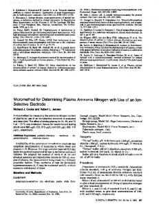
We consider a multiple-relay cooperative communication system shown in Figure. 1. The source cooperates with n relays in information transmission. We assume time division duplex (TDD) system and the whole frame length is 2L. In the first half of the frame, the source broadcasts information to the destination and all the relays. During second half of the frame, the relays make estimations based on the received signals from the source, re-modulate the estimated signals before forwarding to the destination. At each node of the system, differential BPSK is adopted. We assume single antenna at each node, and the links from relays to destination use orthogonal channels.
(1)
x≥0
(2)
and the cumulative distributed function (cdf) is given by [9] P (x) = 1 − e−x ,
x≥0
(3)
According to the knowledge of ordered statistics [10], we can get the pdf and cdf of |hjeq |2 as, peq (x)
=
� 2 � � 2 [P (x)]i−1 [1 − P (x)]1−i [i − 2P (x)] p (x) i
=
2e−2x
i=1
(4)
and Peq (x) =
� 2 � � 2 i 2−i [P (x)] [1 − P (x)] i i=1
=
1 − e−2x
(5)
The destination receives signals from the source in the first half of the frame, and from the n relays in the second half of the frame. It is well known that maximumratio combining is the optimal linear combining technique. However, in order to get the full CSI of each link, the receiver complexity will be relatively high, especially in this distributed environment. Therefore, we choose the selective combining technique, which only works on one of the diversity branches. Upon receiving signals from the n relays, the receiver chooses the strongest branch for further signal processing. The single selected relay link, denoted by I, is determined by I = argmax{|hjeq |2 }
(6)
1≤j≤n
Figure 1: Block model for a multi-relay cooperative system We consider a flat Rayleigh fading environment. The channel fading coefficient for each link between the source and the j th relay, is defined as hjSR , the channel coefficient for each link between the j th relay and the destination is defined as hjRD , j = 1, · · · , n, and the channel for the direct link between the source and the destination is hSD . In order to consider the effect of imperfect estimation at the relays, we replace each two-hop source-relay-destination link with an equivalent one-hop link, Ljeq . Since the overall performance of this equivalent link should be bounded by the weaker link between the source-relay link and the relay-destination link, then for the simplicity of analysis,
which is the strongest link among all the n equivalent onehop links. We rearrange |hjeq |2 , j = 1, · · · , n in ascending order and (l)
(1)
denote them by |heq |2 , where 1 ≤ l ≤ n and |heq |2 ≤ (2) (n) |heq |2 ≤ · · · ≤ |heq |2 . According to Eqn. (6), the selected branch corresponding to the nth order statistic will (n) be |heq |2 . With the pdf and cdf of |hjeq |2 in Eqn. (4-5), (n)
we can work out the pdf of |heq |2 . It is given by n−1
peq (x) p(n) (x) = n [Peq (x)] � � −2x −2x n−1 1−e = 2ne
(7)
This full text paper was peer reviewed at the direction of IEEE Communications Society subject matter experts for publication in the ICC 2008 proceedings.
3
PERFORMANCE ANALYSIS
In this section, we present the performance analysis for the proposed scheme. We refer to Figure. 1 as the system model where we will focus in the performance analysis. In the first half of the frame, the source broadcasts the differentially modulated symbols x (n) to both the relay and the destination. x (n) is calculated as x (n) = x (n − 1) d (n)
(8)
maximum likelihood (ML) approach to reach the following linear combiner [7], ∗ ∗ (n − 1) ySD (n) + yRD (n − 1) yRD (n) (13) z (n) = ySD
However, realistically it is impossible to obtain perfect estimation at the relay. If we take the imperfect estimations into consideration, the combiner output will be modified by considering the equivalent link SNR of the best sourcerelay-destination link. Eqn.(13) will be modified into [6] (n)
where n = 1, . . . , 2L, and d (n) ∈ [−1, +1] is a stream of z (n) = y ∗ (n − 1) y (n) + γeq y ∗ (n − 1) y (n) m SD RD SD (n) RD BPSK symbols. Here the initially modulated symbol is γRD x (0) = 1. The received signals at the destination can be (14) calculated as Finally, the estimation of the transmitted symbol will be made according to the sign of zm (n), ySD (n) = hSD x (n) + nSD (n) � = hSD x (n − 1) d (n) + nSD (n) 1 zm (n) > 0 ˆ (15) d (n) = = ySD (n − 1) d (n) + nSD (n) − nSD (n − 1) d (n) −1 zm (n) ≤ 0 =
ySD (n − 1) d (n) + u (n)
(9)
For differential BPSK modulation, the conditional BER is where u (n) = nSD (n) − nSD (n − 1) d (n). Similarly, we given by [9] have the received signal at the relay K−1 � 1 ySR (n) = hSR x (n) + nSR (n) Cn γTn (16) Pb (γT ) = 2K−1 e−γT 2 = hSR x (n − 1) d (n) + nSR (n) n=0 =
ySR (n − 1) d (n) + nSR (n) − nSR (n − 1) d (n)
=
ySR (n − 1) d (n) + v (n)
=
hRD x ˆ (n) + nRD (n) ˆ (n − 1) d˜(n) + w (n) hRD x
where K is the number of branches combined at the receiver, γT is the instantaneous total SNR combined at the where v (n) = nSR (n) − nSR (n − 1) d (n). Upon receiving receiver from the K branches, which is given by the transmitted symbols from the source, the relay makes K � an estimation for each received symbols. Because d (n) are γi (17) γT = a sequence of BPSK symbols, the estimation rule can be i=1 formulated as and the coefficient Cn is calculated as � ∗ (n − 1) ySR (n) > 0 1 ySR ˜ (11) d (n) = � ∗ K−1−n � (n − 1) ySR (n) ≤ 0 −1 ySR 1 � 2K − 1 Cn = (18) j n! j=0 where (·)∗ represents complex conjugate. Then, the relay differentially re-modulates d˜(n) into x ˆ (n) before forwarding to the destination in the second half of the frame. The In our system, there are two branches combined at the received signal at the destination at the second half of the destination, one is the direct link which is from the source to the destination, the other is an equivalent single link of frame will be the best source-relay-destination path. Therefore, yRD (n)
= = =
(10)
yRD (n − 1) d˜(n) + nRD (n) − nRD (n − 1) d˜(n) (12) yRD (n − 1) d˜(n) + w (n)
where w (n) = nRD (n) − nRD (n − 1) d˜(n). In Eqn.(9), Eqn.(10) and Eqn.(12), nSR (n), nSD (n), and nRD (n) are the noise components at the relay and the destination nodes. Each of them is an independent sample of the zero mean complex Gaussian random variable with the one sided power spectral density of N0 . Here hSR and hRD are the channel fading coefficients of the best source-relay-destination link that has been selected. The destination combines the received signals from both the best relay node and the source before the combiner output is sent to make a decision. The received signals from the direct source-destination link and the signals received from the best relay-destination link are actually independent and Gaussian random variables. We can follow a
(n) γT = γSD + γeq
(19)
The conditional BER in Eqn. (16) will be simplified as (n) Pb (γSD , γeq )=
� (n) 1� (n) 4 + γSD + γeq e−(γSD +γeq ) 8
(20)
where γT is replaced by the summation of the instantaneous SNR of the direct source-destination link and the instantaneous SNR of the equivalent link, since γSD is in(n) dependent of γeq . (n)
Since γSD is independent of γeq , the average BER can be obtained by averaging Eqn. (20) with respect to γSD (n) and γeq , and arrive at [9] ∞ ∞ � � (n) 1 (n) Pb = 4 + γSD + γeq e−(γSD +γeq ) 8 (21) 0 0 (n) (n) p(γSD )p(n) (γeq )dγSD dγeq
This full text paper was peer reviewed at the direction of IEEE Communications Society subject matter experts for publication in the ICC 2008 proceedings.
where p(γSD ) =
1 −γSD /¯γ e γ¯
(22)
and (n) )= p(n) (γeq
�n−1 (n) (n) 2n � 1 − e−2γeq /¯γ e−2γeq /¯γ γ¯
(23)
To get the closed-form of the average BER, we separate Eqn. (21) into two parts,
From this equation, we can see that for a multiple-relay system with n relay nodes, the diversity order can be achieved is n + 1, if a simple selective combiner is used at the destination node. Let’s consider a special case where n = 1, which means a single relay system. Then asymptotically, it can be further simplified as Pb =
� � 5 −2 γ¯ + o γ¯ −2 2
(31)
We can see that a total diversity order of 2 is achieved in Pb1 + Pb2
∞ � this single relay system. 1 ∞ −γeq −γSD 1 −γSD /¯ γ e = e (4 + γSD ) e dγSD 8 0 γ¯ 0 � � � � (n) (n) 4 SIMULATION RESULT d γeq p(n) γeq
� ∞ (n) 1 ∞ 1 γeq e−γeq e−γSD e−γSD /¯γ dγSD + We consider the multiple-relay system shown in Figure. 1 8 0 γ ¯ 0 with slow Rayleigh fading channels, and verify our analyt� � � � (n) (n) d γeq (24)ical result with simulation. We assume that the source p(n) γeq node and the relay nodes communicate with the same Here, using Eqn. 3.312 in [11], we further simplified Pb1 destination node with one antenna at each node. We also assume that the frame size is 130, and the modulainto tion scheme we adopt here is differential BPSK. The BER � � 2 ∞ n−1 (n) 2n (n) 4¯ γ (1 + γ¯ ) + γ¯ −γeq −2γeq /¯ γ curves are plotted against the average SNR. 1 − e Pb1 = e 2 γ¯ 8¯ γ (1 + γ¯ ) 0 In Figure. 2, we can see that at high SNR region, the (n) (n) ·e−2γeq /¯γ dγeq theoretical BER of the differential selective relay protocol � � γ ¯ matches with the simulation result. Here, the ML algo4 + 5¯ γ 2nΓ 1 + 2 Γ (n) � � = rithm is used to estimate the transmitted symbols at the γ ¯ 2 8 (1 + γ¯ ) Γ 1 + n + 2 destination. For the selective relay protocol, among the 4 + 5¯ γ 2n! multiple relays, we choose the strongest relay link. We � � = (25) n γ ¯ 2 8 (1 + γ¯ ) set both the source and relay have the half of total transj=1 2 + j
∞ x−1 −t mitted power, so that the sum of the transmitted power e dt is the Gamma function. Then from both source and relay for the relay system is identiwhere Γ (x) = 0 t using Eqn. (3.432) in [11], we can simplify Pb2 into cal to that of the source-destination non-cooperative direct ∞ � �n−1 transmission. We can see that if there are n relay nodes (n) 2n (n) 2n (n) −γeq 1 − e−2γeq /¯γ γeq e Pb2 = in the network to help the source to convey information to 8¯ γ (1 + γ¯ ) 0 γ¯ the destination, the differential selective relay can achieve (n) (n) ·e−2γeq /¯γ dγeq a diversity order of n + 1, which is shown by the steep� � n−1 ness of the BER curves. For the special case of n = 1, 2 � n¯ γ n−1 n+k−1 = (−1) the system is simplified into a single relay system. The k 16¯ γ (1 + γ¯ ) k=0 diversity achieved is 2, as the information takes two paths 1 to the destination, one is the direct path from the source ·� �2 (26) to the destination, and the other is the indirect source2 γ ¯ γ ¯ 4 + 2 +n−k−1 relay-destination path. When there are 2 relay nodes in the network, the selective relay protocol can achieve a diNow, we combine Eqn. (25) and Eqn. (26) to get the versity order of 3, which is indicated by the steeper slope average BER, expressed as of the BER curve. Pb
Pb
=
=
2n! n¯ γ2 4 + 5¯ γ � γ¯ �+ (27) 2 n 16¯ γ (1 + γ¯ ) 8 (1 + γ¯ ) j=1 2 + j � � n−1 � 1 n−1 · (−1)n+k−1 � 2 �2 k γ ¯ γ ¯ k=0 + 2 +n−k−1 4
As γ¯ → ∞, the asymptotic BER will be � � γ −(n+1) + o γ¯ −(n+1) Pb = 5 · 2n−2 n!¯
(28)
We write f (x) = o[g(x)], as if lim
x→x0
x → x0
f (x) =0 g(x)
(29) (30)
In Figure. 3, we consider the special case where there is only one relay node in the cooperative communication system. We adopt ML algorithm to estimate the transmitted symbols. We also include the analytical result of differential EF relay with a Piecewise-Linear (PL) algorithm which was derived in [7] [8]. In [7], the PL is described as a sub-optimum algorithm compared to the ML algorithm when the relay node is making estimation to the received signals from the source. While in our proposal, the ML algorithm is used. It can be shown from the figure that the differential EF relay with ML algorithm outperforms the differential EF relay with PL algorithm by about 0.8dB. We also include the conventional non-cooperative system performance as a reference. For fair comparison, we set
This full text paper was peer reviewed at the direction of IEEE Communications Society subject matter experts for publication in the ICC 2008 proceedings.
−1
−1
10
10
Non−cooperative Differential Modulation Analysis DEF−PL Simulation DEF−ML Analysis DEF−ML
Simulation, n=1 Analytical, n=1 Simulation, n=2 Analytical, n=2 Simulation, n=3 Analytical, n=3
−2
10
−2
10
−3
10
−3
10
−4
BEP
BER
10
−5
10
−4
10
−6
10
−5
10 −7
10
−6
−8
10
10 20
15
10
25
5
10
Figure 2: Performance of proposed differential selective relay
20
15
25
30
SNR(dB)
SNR(dB)
Figure 3: Performance of differential EF relay systems
system
References both the source and relay have the half of total transmitted power, so that the sum of the transmitted power from both source and relay for the relay system is identical to that of the source-destination non-cooperative direct transmission. We can see that with the help of the single relay, the differential EF relay can achieve a higher diversity gain, which is shown by the steepness of the BER curves. At the BER = 10−3 , this EF relay system outperforms the non-cooperative system by 7dB. For non-cooperative communication, the diversity achieved by single antenna system is 1, while the diversity order achieved by the single relay system is 2. The extra diversity gain is contributed by the relay.
5
CONCLUSION
In this paper, we propose a multiple-relay system which consists one source node, multiple relay nodes and one common destination node. We use differential modulation/demodulation at each node and a selective combiner at the destination node. The advantage of differential modulation is that it allows non-coherent detection and it does not require the full CSI, as obtaining CSI at each node of a multiple-relay system is not easy. The selective combiner also does not require the full CSI available at the destination, which greatly simplifies the receiver design complexity. We derive the average BER for this multiplerelay system. In the performance analysis, we take into account the effect of imperfect estimation at the relay nodes, by replacing each of the source-relay-destination links with an equivalent relay-destination link. From the performance analysis, we conclude that this multiple-relay system with selective combiner can achieve full diversity.
[1] A. Sendonaris, E. Erkip and B. Aazhang,“Increasing Uplink Capacity via User Cooperation Diversity”,Proc. IEEE ISIT, p. 196,Aug. 1998 [2] A. Sendonaris, E. Erkip and B. Aazhang, “User Cooperation Diversity-part I: System Description”, IEEE Trans. Commun., vol. 51, pp.1927-1938, Nov. 2003. [3] A. Sendonaris, E. Erkip and B. Aazhang, “User Cooperation Diversity-part II: Implementation aspects and performance analysis”, IEEE Trans. Commun., vol. 51, pp.1939-1948, Nov. 2003. [4] N. Laneman,D. N. C. Tse and G. W. Wornell,“Cooperative Diversity in Wireless Networks: Efficient Protocols and Outage Behavior”, IEEE Trans. Inf. Theory, vol. 50, no. 12, pp. 3062-3080, Dec. 2004. [5] Nosratinia, A.; Hunter, T.E.; Hedayat, A.; “Cooperative communication in wireless networks”,IEEE, Communications Magazine, Volume 42, Issue 10, Oct. 2004 Page(s):74 - 80 [6] T. Wang, A. Cano, G. B. Giannakis, and N. Laneman, “High-Performance Cooperative Demodulation with Decode-and-Forward Relays,” IEEE Trans. on Commun. 2007 (to appear) [7] Q. Zhao, H. Li, “Differential Modulation for Cooperative Wireless Systems”, IEEE Trans. Signal Proc. , vol. 55, no. 5, pp. 2273-2283, May. 2007. [8] D. Chen, J. N. Laneman, “Modulation and Demodulation for Cooperative Diversity in Wireless Systems”, IEEE Trans. Wireless Commun., vol. 5, no. 7, pp. 1785-1794, Jul. 2006. [9] J. Proakis, “Digital Communications”, 4th edition, McGRAW-HILL, 2001. [10] H. A. David,“Order Statistics”, John Wiley & Sons Ltd, 1970. [11] I. S. Gradshteyn and I. M. Ryzhik, “Table of Integrals, Series, and Products”, 6th edition, San Diego, CA: Academic, 2000.