Selected Papers
Differential-phase-shift Quantum Key Distribution Toshimori Honjo† and Kyo Inoue Abstract Quantum cryptography promises to provide communications with unconditional security on the basis of the physical principles of quantum mechanics. We have proposed a quantum key distribution protocol called a differential-phase-shift quantum key distribution (DPS-QKD). This scheme has several advantages including suitability for fiber transmission and highly efficient key generation. In this paper, we review quantum cryptography technologies and then describe our scheme DPS-QKD. In an experiment using a planar lightwave circuit Mach-Zehnder interferometer, DPS-QKD achieved stable polarization-independent operation during 20-km fiber transmission. The raw key creation rate was 3076 bit/s with a 5.0% quantum bit error rate.
1. Introduction and background Secure communications is one of the most important topics in the telecommunication field. At present, cryptography, the art of hiding information in a string of bits meaningless to any unauthorized party, is usually used for secure communications. Classical cryptography, whose security is based on the need for a large amount of computation, is widely used in today’s communications systems. However, this type of cryptography will be vulnerable to attack from clever eavesdroppers in the future. For example, RSA public key cryptography (named after Rivest, Shamir, and Adleman) is based on the difficulty of factoring large integers. If an efficient way to factorize large integers is found, RSA will no longer be secure. In fact, with the advent of quantum computers, it will be possible to factor large numbers in an instant. Therefore, a lot of activity is being focused on finding cryptography schemes that will provide ultimately secure communications. Now quantum cryptography is in the spotlight. Even if a quantum computer is made, quantum cryptography provides ultimately secure communications because its security is based not on computational † NTT Basic Research Laboratories Atsugi-shi, 243-0198 Japan E-mail:
[email protected]
26
power but on the laws of quantum mechanics [1]. 1.1 Quantum key distribution Quantum cryptography allows two physically separated parties to create a random secret key. For this reason, it is often called quantum key distribution (QKD). Once a sender (Alice) and a receiver (Bob) share random secret keys, they can achieve perfectly secure communication using a one-time-pad method, which has been proved to provide complete security. In short, QKD is a technique for establishing a quantum channel on which Alice and Bob can detect the existence of an eavesdropper. When this quantum channel is available, Alice and Bob can create a key through it and can be assured of the security of the key. The quantum channel is constructed based on the following theorem in quantum mechanics: an eavesdropper (Eve) cannot acquire any information from a quantum state transmitted from Alice to Bob without disturbing its quantum state, so when Eve acquires some information from the quantum state, the state is perturbed and a key bit error is induced. This theorem is deduced from the following laws of quantum mechanics. (1) With an appropriate measurement basis, a certain physical property of a quantum state is determinately measured. But with another measurement basis, the physical property is measured probabilistically. NTT Technical Review
Selected Papers
(2) No one can clone an unknown quantum state in general. Based on the above idea, Alice and Bob can generate a secret key as follows. Alice encodes the bit information onto quantum states and sends it to Bob through the quantum channel. Bob randomly chooses a measurement basis for each quantum state and measures the state. After that, Bob discloses the measurement basis and then Alice and Bob choose the proper bits, which could be a raw key. To check the existence of an eavesdropper, Alice and Bob choose a fraction of their raw keys and compare them over a public (classical) channel. If an eavesdropper measures the quantum state to steal the information, the quantum state changes and a key bit error is induced with some probability. Thus, from the error rate in the test bits, Alice and Bob can detect whether an eavesdropper exists or not and also evaluate the amount of leaked information, assuming that all errors, including those due to imperfections in practical systems, result from eavesdropping. If the estimated information leakage exceeds an upper bound, they discard their raw keys. If the error rate or leakage is small, they perform the following sequence. First, Alice and Bob perform error correction to obtain a matched bit string. The obtained string may not be completely private. To eliminate the possibility of leakage, Alice and Bob perform privacy amplification [1], which shortens the
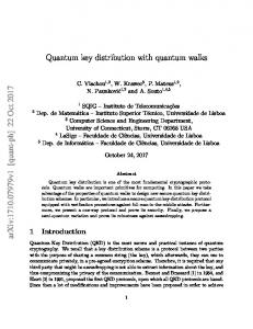
error-corrected keys using a universal hash function. Then they distill a fully secret key, which can be used with full confidence to encrypt a message. 1.2 Conventional QKD protocol and implementation Several protocols have been proposed for the above idea, such as BB84 [2], B92 [3], and E91 [4]. Here, we overview BB84, the most famous QKD protocol, to explain the above idea. We also introduce Plug & Play QKD, which is a widely performed fiber-based BB84-QKD implementation. 1.2.1 BB84 protocol BB84, which was proposed by Bennett and Brassard in 1984, is a QKD protocol using four quantum states with two non-orthogonal bases. In practice, a single photon is used as a quantum state. In implementing the BB84 protocol, there are two ways to encode bit information onto a single photon: polarization encoding and phase encoding. Here, we describe polarization encoding because it is easy to understand intuitively. Figure 1 shows the sequence of the BB84 protocol. First, Alice sends single photons in one of four polarization states: vertical linear, horizontal linear, right circular, or left circular. She randomly chooses one of the polarization states for each photon and records her choice. Bob has two filters and selects one of
Eve Filter 1
Filter 2
Eavesdropping Intercept Resend
Filter 1
Bob
Alice Polarization Right state
Horiz.
Left
Vert. Filter 2
Sent data
Photon
Bob’s measurement biases
Bias-matched data
Raw key 0 1
Quantum channel Classical channel
Measurement results Measurement biases
Bias-matched data
0
Raw key 0 1
0
Fig. 1. Sequence of the BB84 protocol using polarization encoding.
Vol. 2 No. 12 Dec. 2004
27
Selected Papers
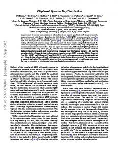
them randomly before measuring each photon. One of the filters allows him to distinguish between horizontally and vertically polarized photons, whereas the other distinguishes between right and left circularly polarized ones. When Bob chooses the matched filter, he gets the correct output. When Bob chooses the filter that does not correspond to the polarization state sent by Alice, each outcome can occur with 50% probability. Bob records the filters used and the outcomes. Second, after receiving a sufficient number of photons, Bob announces through a public channel which filter he used for each photon, but does not reveal the measurement results. Alice compares Bob’s data with the list of states she sent, and tells Bob for which photons he used a compatible filter, but not the polarization states themselves. In cases where states and filters are compatible, they keep the data. Otherwise the data are simply discarded. Under the agreement that vertical linear or right circular polarization states denote a “0” bit and horizontal linear or left circular polarization states denote a “1” bit, Alice and Bob can share the same bit string, which could be a raw key. Third, Alice and Bob each choose a fraction of their raw keys and compare them over a public channel to assess the secrecy of their communication. They perform error correction and privacy amplification, as described in the previous section. Then, Alice and Bob can share a secret key, which can be used with perfect confidence to encrypt a message. 1.2.2 Plug & Play QKD Though QKD using polarization states is easy to understand, it is not suitable for fiber transmission, because the polarization state is not maintained because of the birefringence in optical fiber. A QKD setup suitable for fiber transmission has been pro-
posed by Muller et al. [5]. In this system, instead of being encoded onto polarization states, the bit information is encoded onto the relative phase of the superposition of single photon states. This is what is known as phase coding. Most experiments and commercial products use this QKD setup. Figure 2 shows the schematic diagram of the Plug & Play QKD system. Bob injects a light pulse through a circulator. The pulse is split into two pulses at a coupler. One pulse takes the short arm and the other takes the long arm. A polarization controller is set in each arm so that the pulse is completely transmitted at the polarization beam splitter. The pulses propagate to Alice and are reflected by a Faraday mirror. One pulse is phase modulated at PM(a) by φa = {0 or π or π or 3π } at Alice’s site. The light power is 2 2 attenuated to be 0.1 photon per pulse, and then the pulses travel back to Bob. Thanks to the effect of the Faraday mirror, the birefringence of the optical fiber is automatically compensated, and the pulse comes back orthogonally polarized. Each pulse travels through the counter arm. The light that passes through the long arm is phase modulated at PM(b) by φb = {0 or π } at Bob’s site. Since the pulses travel 2 through the same optical path, they stably interfere with each other at the coupler. The relative phase between φa at Alice’s site and φb at Bob’s determines which photon detector clicks, DET1 or DET2. With this setup, Alice randomly chooses one of four phase modulations: 0, π , π, or 3π , which corresponds 2 2 to the choice of polarization states mentioned in the BB84 protocol explanation. Bob randomly chooses one of two phase modulations: 0 or π , which corresponds 2 Bob
Alice Faraday mirror
Phase Fiber modulator Attenuator PM(a)
φa = 0,
π 3π , π, 2 2
Polarization beam splitter
DET1 DET2
Phase modulator PM(b)
φb = 0,
π 2
50:50 coupler
Circulator Intensity modulator Laser diode
Fig. 2. Schematic diagram of the Plug & Play QKD system.
28
NTT Technical Review
Selected Papers
to the choice of filters. After receiving a sufficient number of photons, Bob announces on a public channel which phase modulation he imposed on each pulse. Alice compares this sequence with the list of her phase modulations and tells Bob for which photons he imposed compatible phase modulations. Under the agreement that the phase difference φa – φb of 0 denotes a “0” bit and the phase difference φa – φb of π denotes a “1” bit, Alice and Bob can share the same bit string, which could be a raw key. The great advantage of this setup is that the polarization change in the transmission line is automatically compensated. However, this scheme has some disadvantages. First, the light traveling in an optical fiber is scattered by inhomogeneities. A small fraction of the light is recaptured by the fiber in the backward direction, which is called Rayleigh backscattering. Because of the intrinsically bi-directional nature of the system, backscattered photons induce errors. To avoid this Rayleigh backscattering, the repetition frequency must not be too high. Second, light transmitted through the fiber must be phase-modulated at Alice’s site, so polarization control is needed. Third, there are many components, such as a phasemodulator, polarization controllers, a polarization beam-splitter, and a circulator, at Bob’s site. These components increase the excess loss, so many of the photons that have traveled back from Alice vanish at Bob’s site. Bit information 0 1 1 0 π π 0 π π
Setup Alice Coherent light source
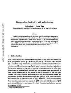
2. Differential-phase-shift QKD We proposed DPS-QKD [6] to overcome the disadvantages of conventional QKD protocols. This scheme uses the uncertainty of the detection time of photons and encodes the bit information onto the phase difference between two sequential pulses. 2.1 Protocol Figure 3 shows the setup and protocol sequence of the DPS-QKD scheme. Alice randomly phase-modulates a pulse train of weak coherent states by {0, π} for each pulse and sends it to Bob with an average photon number of less than one per pulse. Bob divides each incoming pulse into two paths and recombines them with a 50:50 beam splitter, where the path-length difference is set equal to the time interval of the sequential pulses. Photon detectors are placed at the two outputs of the recombining beam splitter. At the detectors, the partial wave functions of two sequential pulses interfere with each other, as illustrated in Fig. 3. With an appropriate phase in the interferometer, detector 1 clicks for 0 phase difference between the two consecutive pulses and detector 2 clicks for π phase difference. Using the above setup, Alice and Bob create a raw key by the following protocol. After raw transmission, Bob tells Alice the time instances at which a photon was counted. From this time information and her modulation data, Alice knows which detector clicked at Bob’s site. Under the agreement that a click Phase DET1 difference 0
Bob 1-bit delay circuit
< 1 photon per pulse
DET2 π
Phase Attenuator modulator
π π 0 π π π π 0 π π π π 0 π π t4 t3 t2 t1
Protocol
Time
Bob
Alice Time
t1 t2 t3 t4 t5 t6 t7
Phase difference
0 π 0 0 0 π 0
Time Detector
t2 Det2
t4 Det1
t6 Det2
Time
t2
t4
t6
Phase difference
π
0
π
Raw key bits
1
0
1
Raw key bits
1
0
1
Fig. 3. Setup and protocol of the DPS-QKD scheme.
Vol. 2 No. 12 Dec. 2004
29
Selected Papers
by detector 1 denotes “0” and a click by detector 2 denotes “1”, for example, Alice and Bob obtain an identical bit string. 2.2 Eavesdropping DPS-QKD uses the uncertainty of the detection time of photons. If an eavesdropper steals a photon and sends a fake one, Alice and Bob notice the existence of the eavesdropper from the bit error induced by the detection timing error. Here, we show one example of security against one type of intercept-resend attack. Eve intercepts and measures transmitted states and resends a false signal to Bob according to her measurement, as illustrated in Fig. 4. Eve cannot measure every phase difference because the transmitted state is less than one photon per pulse. Eve thus sends a signal only when she detects a photon. She sends a single photon split into two time slots through an interferometer identical to Bob’s, in which the relative phase between the two time slots is 0 or π depending on the measured phase difference. For unmeasured time slots, on the other hand, she sends no photon. This fake signal generates the same count rate in Bob’s detectors as the original one. Bob does not notice the eavesdropping from the photon counting rate. However, a bit error is introduced from this fake signal as follows. When a photon split into two time slots arrives at Bob’s site, he could count a photon at one of three possible time instances: (1) when a photon passes through the short path in Eve’s interferometer and the short path in Bob’s interferometer, (2) when a photon passes through Eve’s short path and Bob’s long path or through Eve’s long path and Bob’s short path, or (3) when a photon passes through Eve’s long path and
Bob’s long path. In the second case the detector clicks according to the phase difference between the two time slots, which gives a correct answer. Bob does not notice any eavesdropping in this case. However, no interference occurs and the detectors click randomly at the first and third time instances. A bit error is introduced by these detection events. The probability of clicks at the first or third time instances is 1 , so 2 1 the error rate is . The eavesdropping is revealed 4 from this error rate. 2.3 Features DPS-QKD has several advantages over conventional QKD schemes. First, this scheme is polarization insensitive, provided that a polarization insensitive interferometer is available. In our scheme, the information is carried by the phase difference between two sequential pulses. Though the polarization state changes after propagation through the fiber, two sequential pulses experience the same change so they have the same polarization state at the fiber output, as long as the time interval of two sequential pulses is much shorter than the time constant of the change in the fiber. This condition is satisfied in actual systems because changes in temperature and/or mechanical pressure have a slow time constant compared with the pulse interval. Therefore, nearly perfect interference between two sequential pulses is possible independent of polarization change in fiber. Second, DPS-QKD has a simpler receiver setup and thus smaller loss than other QKD setups. For example, in the Plug & Play QKD setup, there are (as men-
Eve 1-bit delay circuit
DET1 DET2
0 π π
Alice
Bob 1-bit delay circuit
DET1 DET2
t3 t2 t1 Time
Fig. 4. Intercept-and-resend attack.
30
NTT Technical Review
Selected Papers
tioned before) many components, which increase the excess loss at the receiver’s site. In DPS-QKD on the other hand, there is only one interferometer at the receiver’s site so the excess loss is much smaller. Very few photons are lost at the receiver’s site, which means we can achieve a high key generation rate. Third, key generation efficiency is high compared with conventional QKD protocols. In the BB84 protocol, half of the received photons are discarded because they are basis-mismatched. On the other hand, the DPS-QKD protocol utilizes all photons for creating a key, which provides high efficiency. Fourth, in the DPS-QKD setup, it is possible to send a light pulse at a high repetition frequency. In the Plug & Play QKD setup, the repetition frequency cannot be made too high because of Rayleigh backscattering. On the other hand, DPS-QKD is a one-way transmission system so the light can be transmitted at a high repetition frequency and we can achieve a high key generation rate. 2.4 Experiment As described above, the DPS-QKD scheme has some advantages over conventional QKD schemes. One of the most characteristic advantages is the polarization insensitive operation. However, this presupposes that a stable and polarization insensitive interferometer is available. We performed an experiment using a Mach-Zehnder interferometer fabricated using a planar lightwave circuit (PLC) based on silica waveguide technologies [7]-[9].
2.4.1 Performance of the PLC Mach-Zehnder interferometer Before conducting the transmission experiment, we evaluated the performance of the PLC Mach-Zehnder interferometer. We used one packaged with input and output fibers. A peltier device and a thermistor were attached to the PLC chip to control the temperature, so the phase difference between the two waveguide paths could be stably controlled. The path-length difference was 20 cm, which introduced a one-bit delay of 1 ns at 1 Gbit/s. The excess loss of the interferometer was 2.64 dB (fiber-to-fiber). The PLC is sensitive to the polarization state due to its birefringence (about 10–4), which is induced by the residual stress in the silica glass film. This results in a polarizationdependent spectral response shift and degrades the extinction ratio. The shift can be eliminated using a birefringence compensation technique or by choosing the wavelength at which the shift is zero. To evaluate the stability of the interferometer, we measured the extinction ratio at various temperatures for the best and worst polarization states. Figure 5 shows the results, where the upper and lower lines are the extinction ratios for the worst and best polarization states, respectively. Even for the worst polarization state, an extinction ratio of less than –20 dB (1%) was obtained under temperature control within 0.05°C. At the optimum temperature, the polarization dependence was small, so that the extinction ratio ranged from 0.27 to 0.46% when the input polarization state was varied. These results show that stable polarization-independent operation is possible using a PLC
Extinction ratio (dB)
–10
–15
–20
–25
21.7
21.74
21.78 Temperature (°C)
21.82
21.86
Fig. 5. Extinction ratio of the PLC Mach-Zehnder interferometer as a function of temperature.
Vol. 2 No. 12 Dec. 2004
31
Selected Papers
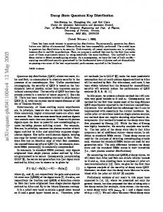
Mach-Zehnder interferometer. 2.4.2 Experimental setup Figure 6 shows the experimental setup. The transmitter, Alice, randomly phase-modulated a pulse train of coherent light by {0, π} for each pulse. The pulse train was created by intensity-modulating continuous wave (CW) light from an external-cavity laser diode (wavelength: 1551 nm). The pulse width was 125 ps and the repetition rate was 1 GHz. The phase modulation was imposed with a LiNbO3 modulator driven by a pulse pattern generator. Then, the light power was attenuated to be 0.1 photon per pulse on average and was injected into a 20-km fiber (propagation loss: 4.46 dB). The receiver, Bob, measured the phase difference between two sequential pulses using a PLC Mach-Zehnder interferometer, which was set to provide the best extinction ratio for the worst polarization state. Photon detectors were placed at the two outputs of the interferometer. With an appropriate phase in the interferometer, detector 1 clicked for 0 phase difference between two consecutive pulses and detector 2 clicked for π phase difference. Avalanche photodiodes (APDs) were used as the photon detectors, which were gated at 5 MHz. The gate pulse was synchronized with the light pulse. The quantum efficiency was about 4.24% and the dark count probability was about 2.21 × 10⁻⁵ per gate. In detecting photons, Bob recorded the photon arrival time and which detector clicked. Using the above setup, Alice and Bob created raw secret keys at their respective sites, following the protocol described in the previous section. The quantum bit error rate
(QBER) was estimated from the difference between the created keys. The polarization state was set to produce the worst QBER in this measurement to test the worst-case scenario. The raw key generation rate was estimated from the number of photons counted and the time over which the time interval analyzer (TIA) actually measured. The results are shown in Fig. 7, where the QBER and the raw key generation rate are plotted as a function of the time window, which here is the margin for the photon arrival time. Since our APD and TIA had some timing jitter, the measured arrival time fluctuated and errors may have been induced. To reduce this timing error, Bob took data within the time window, at the expense of the key generation rate. When the time window was 0.6 ns, key creation was performed at a rate of 3076 bit/s with a QBER of 5.0%. A sufficient QBER was obtained to create a secret key after error correction and privacy amplification. 3. Conclusion After reviewing quantum cryptography technologies, we described our QKD protocol called differential-phase-shift QKD. This scheme makes use of the uncertainty in the photon detection time. It has a simple configuration for practical implementation and is suitable for fiber transmission provided a stable polarization-insensitive interferometer is available. We showed that a PLC interferometer based on silica waveguide technologies provides polarizationinsensitive operation stable enough for the DPS-
Clock Alice Pulse pattern generator
Pulse generator 1 GHz
0.1 photon per pulse
1 GHz
External Intensity cavity laser modulator (λ = 1551 nm) (LiNbO3)
Phase Attenuator modulator (LiNbO3) 0 π π
1 GHz 125 ps
Bob Glass-waveguide Pulse Mach-Zehnder generator interferometer 5 MHz
Optical fiber
20 km (4.46 dB)
20 cm (2.64 dB)
Det Det (APD)
Time interval analyzer (TIA)
Fig. 6. Experimental setup.
32
NTT Technical Review
Selected Papers
8.5
7.5 3000 6.5
2000
5.5
QBER (%)
Raw key generation rate (bit/s)
4000
4.5
1000
3.5 0 0.2
0.4
0.6
0.8
1
Time window (ns)
Fig. 7. QBER and the raw key generation rate as a function of the time window.
QKD in practice. In a transmission experiment over a 20-km fiber, we obtained a key generation rate of 3076 bit/s and a QBER of 5.0%. These experimental results indicate that practical implementation of the DPS-QKD scheme should be possible. Currently, the key generation rate is limited by the performance of the photon detector. A higher rate should be possible by improving the photon detector performance. We plan to develop a high-performance photon detector and use it in an experiment to show the DPS-QKD’s potential for a high key generation rate compared with other conventional QKD schemes. 4. Acknowledgment We would like to thank Dr. H. Takahashi at NTT Photonics Laboratories for providing the PLC MachZehnder interferometer.
[7]
[8] [9]
022317, 2003. T. Honjo, K. Inoue, and H. Takahashi, “Differential-phase-shift quantum key distribution experiment using a glass waveguide interferometer,” CLEO/IQEC 2004, ITuJ1, 2004. A. Himeno, K. Kato, and T. Miya, “Silica-based planar lightwave circuits,” IEEE J. Sel. Top. Quantum Electron, Vol. 4, p. 913, 1998. Y. Inoue, H. Takahashi, S. Ando, T. Sawada, A. Himeno, and M. Kawachi, “Elimination of Polarization Sensitivity in Silica-Based Wavelength Division Multiplexer Using a Polyimide Half Waveplate,” J. Lightwave Technol., Vol. 15, p. 1947, 1997.
Toshimori Honjo Research Engineer, Optical Science Laboratory, NTT Basic Research Laboratories. He received the B.S. degree in information science and M.S. degree in mathematical and computing sciences from Tokyo Institute of Technology, Tokyo in 1996 and 1998, respectively. In 1998, he joined NTT Software Laboratories. Since 2003, he has worked at NTT Basic Research Laboratories. His current work is research on quantum information technologies and quantum cryptography.
References [1] [2]
[3] [4] [5]
[6]
N. Gisin, G. Ribordy, W. Tittel, and H. Zbinden, “Quantum cryptography,” Rev. Mod. Phys., Vol. 74, p. 145, 2002. C. H. Bennett and G. Brassard, “Quantum cryptography: public key distribution and coin tossing,” Proc. Internat. Conf. Computer Systems and Signal Processing, pp. 175-179, 1984. C. H. Bennett, “Quantum cryptography using any two nonorthogonal states,” Phys. Rev. Lett., Vol. 68, p. 21, 1992. A. K. Ekert, “Quantum cryptography based on Bell’s theorem,” Phys. Rev. Lett., Vol. 67, p. 6, 1991. A. Muller, T. Herzog, B. Huttner, W. Tittel, H. Zbinden, and N. Gisin, “‘Plug & play’ systems for quantum cryptography,” Appl. Phys. Lett., Vol. 70, pp. 793-795, 1997. K. Inoue, E. Waks, and Y. Yamamoto, “Differential-phase-shift quantum key distribution using coherent light,” Phys. Rev., Vol. A 68, p.
Vol. 2 No. 12 Dec. 2004
Kyo Inoue Senior Research Engineer, Optical Science Laboratory, NTT Basic Research Laboratories. He received the B.S., M.S., and Ph.D. degrees in applied physics from the University of Tokyo, Tokyo in 1982, 1984, and 1997, respectively. He joined NTT Laboratories in 1984 and conducted research on optical communications. From 2001 to 2003, he was a visiting scholar at Stanford University, USA, where he worked on quantum optics.
33