known, stable bias point is a key part of linear circuit design. We use our large
signal models in this design and analysis. * Only when we want to determine the
...
6.012 - Microelectronic Devices and Circuits
Lecture 14 - Digital Circuits: Inverter Basics - Outline
• Announcements •
Stellar - Two supplemental readings posted
Exam Two - Be the first in your living unit to study for it.
Review - Linear Equivalent Circuits Everything depends on the bias; only low frequency for now
• Digital building blocks - inverters A generic inverter
MOS inverter options
• Digital inverter performance metrics Transfer characteristic: logic levels and noise margins Power dissipation Switching speed Fan-out, fan-in Manufacturability
• Comparing the MOS options And the winner is…. Clif Fonstad, 10/29/09
Lecture 14 - Slide 1
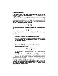
Reviewing our LECs: Important points made in Lec. 14
We found LECs for BJTs and MOSFETs in both strong inversion and sub-threshold. When vbs = 0, they all look very similar: in
iin
iout
Cm
+ v in gi -
gmv in Ci
go
out
+ v out Co common
common
Most linear circuits are designed to operate at frequencies where the capacitors look like open circuits. We can thus do our designs neglecting them.* BJT ST MOS SI MOS Bias dependences:
gi : gm : go :
q IC " F kT q IC kT $ IC
0 q ID n kT $ ID
0 2K o ID # $ ID
ST = sub-threshold
SI = strong inversion
The LEC elements all depend on the bias levels. Establishing a
known, stable bias point is a key part of linear circuit design.
We use our large signal models in this design and analysis.
! Clif Fonstad, 10/29/09
* Only when we want to determine the maximum frequency to which our designs can usefully operate must we include the capacitors.
Lecture 14 - Slide 2
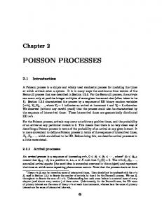
LECs: Identifying the incremental parameters in the characteristics iC
BJT:
iC
ln iB, ln iC
Q
IC
"
IC
Q
iB
"
go
Inc. i B
vCE
vCE
gm = qIC/kT; gπ = βgm with β = diC/diB|Q; go = diC/dvCE|Q MOSFET:
iD
(iD)1/2 Inc. |v BS |
gm Q
Q
go
!
Inc. v GS vDS
VT
vGS = vDS
gm = diD/dvGS|Q; gmb = ηgm with η = -dVT/dvBS|Q; go = diD/dvDS|Q Clif Fonstad, 10/29/09
Lecture 14 - Slide 3
Building Blocks for Digital Circuits: inverters Performance metrics
V DD
A basic inverter
PullUp
Device: on or off Switch: open or closed
+
+ vIN –
• • • • • • •
v IN vOUT Lo (0) Hi (1) Hi (1) Lo (0)
vOUT –
!
Logic gates
V DD
Transfer characteristic Logic levels Noise margins Power dissipation Switching speed Fan-in/Fan-out Manufacturability
Memory cell
V DD
NOR: vA 0 0 1 1
vB 0 1 0 1
vOUT 1 0 0 + vA – 0
NAND: PullUp + + vB –
vOUT –
vA 0 0 1 1
vB 0 1 0 1
vOUT 1 + 1 vA 1 + vB 0 – –
V DD
PullUp +
PullUp
PullUp
vOUT –
Flip-flop !
Clif Fonstad, 10/29/09
Lecture 14 - Slide 4
!
V DD
Inverter metrics: Transfer characteristic The transfer characteristic, vOUT vs vIN, is found applying the large signal models at this node
Node equation : iPD = iPU # 0* % when v IN < VT ,PD % 2 %%K v " V 2 ( ) PD IN T ,PD iPD = $ % when 0 < [v IN " VT ,PD ] < vOUT % K (v " V T ,PD " vOUT 2)vOUT % PD IN %& when 0 < vOUT < [v IN " VT ,PD ] iPU : Depends on the specific pull - up device used.
PullUp
+ vIN –
iPU
iPD + vOUT –
V OUT
For simplicity: α = 1, λ = 0
!
* Note: We can say iPD is zero for the purpose of calculating a transfer characteristic. For power we may want to use: "VT nVt
iPD,off = IS,s"t e
Clif Fonstad, 10/29/09
V IN V DD Lecture 14 - Slide 5
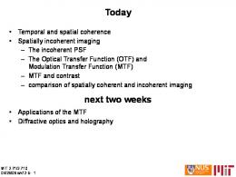
Inverter metrics: Transfer characteristic, cont.
V DD
An example: NMOS
2 # K V 2 PU T ,PU % % when 0 < VT ,PU < [VDD " vOUT ] iPU = $ %K PU [ VT ,PU " (VDD " vOUT ) 2](VDD " vOUT ) % & when 0 < [VDD " vOUT ] < VT ,PU # 0 % + when v IN < VT ,PD % 2 %%K v " V v OUT 2 PD ( IN T ,PD ) iPD = $ % when 0 < [v IN " VT ,PD ] < vOUT – % K (v " V T ,PD " vOUT 2)vOUT % PD IN %& when 0 < vOUT < [v IN " VT ,PD ]
Pull-up: Depletion mode n-channel MOSFET (Note: VT,PU < 0)
Pull-down: Enhancement + mode n-channel MOSFET v IN
!
–
Identify the regions vOUT VDD
vOUT vOUT = VT,PD
PD off
PD sat.
! vOUT = vIN-VT,PD
VDD
PU linear
VDD - vOUT = |VT,PU |
VDD - |VT,PD|
PU saturated.
PD
linear
vIN Clif Fonstad, 10/29/09
VT,PD
VDD
vIN VT,PD
VDD
Lecture 14 - Slide 6
Inverter metrics: Transfer characteristic, cont. Combine the plots; write the node equation in each region and solve. 0 = K PU [ VT ,PU " (VDD " vOUT ) 2](VDD " vOUT )
vOUT VDD
PD off, PU lin.
K PD (v IN " VT ,PD ) 2 = K PU [ VT ,PU " (VDD " vOUT ) 2](VDD " vOUT ) 2
PD sat, PU lin.
VDD - |VT,PD! |
K PD (v IN " VT ,PD ) 2 = K PU VT ,PU 2
PD sat., ! PU sat.
!
!
VT,PD
2
vIN VDD
vOUT = VDD
(VDD " vOUT )
!
2
" 2VT ,PU (VDD " vOUT ) +
! Clif Fonstad, 10/29/09
!
2
2
vOUT
PD lin., PU sat. 2
2
K PD (v IN " VT ,PD " vOUT 2)vOUT = K PU VT ,PU
PD off, PU sat.
0 = K PU VT ,PU
2
VDD VDD - |VT,PD|
K PD 2 v IN " VT ,PD ) = 0 ( K PU
! K PU v IN = (VT ,PD + VT ,PU ) K PD 2 K 2 vOUT " 2(v IN " VT ,PD )vOUT " PU VT ,PU = 0 K PD
vIN VT,PD
VDD Lecture 14 - Slide 7
Inverter metrics: Transfer characteristic, cont.
Is the characteristic really vertical and vOUT indeterminate when both transistors are in saturation? It is if λ = 0 (i.e. no Early effect), but we know this isn't true. We can find the slope when λ ≠ 0 from an LEC analysis about the bias point vOUT = v IN = K PU K PD (VT ,PD + VT ,PU ) . V DD gpu
+ ! v gs = 0 spu -
+ + v IN –
gpd + v in spd , dpu Clif Fonstad, 10/29/09
v OUT –
+ 0
go,pu
gpd
+ v gs = v in spd --
gm,pd v in
dpd , spu go,pu gm,pd v in
id,pu
id,pu
go,pd spd , dpu
+ v out -
dpu go,pu
d + pu v ds = -v out
-s -s pu pu id,pd d + pd v ds = v out go,pd -s pd
gm, pd v out Av " =# v in go, pd + go, pu =#
This is the slope of the "vertical" portion.
2K PD ID $PD ID + $PU ID Lecture 14 - Slide 8
V DD
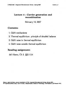
Inverter metrics: Logic levels, noise margins
PullUp
PullUp
vOUT1
+
Stage 1
+ vIN1 -
+
vOUT1 -
+ vIN2 -
vOUT2 = vIN1 -
vOUT Stable solution vIN1 V DD
V HI
Tipping point 45˚
vIN2 V DD
Stage 2
Unstable solution
VM
Tipping point 45˚
Stable solution
V LO vOUT2
Clif Fonstad, 10/29/09
vIN V LO V 1L V M V 1H NML
NMH
V HI Lecture 14 - Slide 9
Inverter metrics: Switching times (gate delay)
When the output goes from LO to HI, the load charge store must be charged through the pull-up device. When the output goes from HI to LO, it is discharged through the pull-down device. V DD V DD
PullUp
PullUp i
iPU
PU
iDischarge + + HI to LO
–
OFF LO to HI
CL
–
Charging cycle: iCharge = iPU
+
ON
+ LO to HI
–
iPD
HI to LO
CL
–
Discharging cycle: iDischarge = iPD – iPU
We can often model CL as a linear capacitor (i.e. a multiple of Cox*) in which case the charge and discharge cycles are found by solving: dv 1 dv 1 " Ch arg e : OUT = iPU (vOUT ) " Disch arg e : OUT = [iPD (v IN ,vOUT ) # iPU (vOUT )] dt CL dt CL Clif Fonstad, 10/29/09
!
Lecture 14 - Slide 10
!
Inverter metrics: Power Total Power: Two components - static and dynamic (switching)
PTotal = PStatic + PDynamic Static:
V DD
Pull-down off: !
+ vIN –
PullUp
V DD PullUp
Pull-down on: iPU
iPD + vOUT –
PStatic,off = IPD,off VDD
+ vIN –
( " 0)
iPU
iPD + vOUT –
PStatic,on = IPU ,onVDD
To estimate the total static power we assume the typical pull-down is off half the time and on half the time.
! Clif Fonstad, 10/29/09
PStatic,ave
1 1 1 ! = PStatic,on + PStatic,off = ( IPD,off + IPU ,on ) VDD 2 2 2 Lecture 14 - Slide 11
Inverter metrics: Power, cont.
Dynamic:
V DD
Charging cycle:
PullUp
V DD
+ + HI to LO
–
Discharging cycle:
iPU
OFF LO to HI
+ LO to HI
–
!
Clif Fonstad, 10/29/09
PTotal =
+
ON
CL
2 Energy dissipated per cycle : CLVDD Cycles per second : f
Total:
PU
iDischarge
–
1 1 2 2 CLVDD Dissipated, CLVDD Stored 2 2
!
PullUp i
iPD
HI to LO
CL
–
1 2 CLVDD Dissipated 2
!
2 PDynamic,ave = f CLVDD
1 2 I + I V + f C V ( PD,off PU ,on ) DD L DD 2 !
Lecture 14 - Slide 12
V DD
MOS
inverters:
5 pull-up choices
PullUp
RL Resistor
pull-up
+ v OUT
+ v IN –
Generic inverter
V DD
+
CL
+ v IN –
–
V DD
V DD
v OUT –
V DD
V DD
V GG (>>V DD )
+ + v IN –
v OUT –
+ + v IN –
v OUT
n-channel, e-mode pull-up* VDD on gate VGG on gate Clif Fonstad, 10/29/09 * Called PMOS when made with p-channel FETs.
–
+ v IN –
+
v OUT
+ v IN
v OUT
–
–
–
+
n-channel, d-mode pull-up (NMOS)
Active p-channel pull-up (CMOS)**
Lecture 14 - Slide 13 ** Notice that CMOS has a larger (~3x) input capacitance.
MOS inverters: Comparing the 5 pull-up choices Ground rules: To make the comparison meaningful, we set the following conditions: 1. We use the same pull-down device with each of the different pull-ups. 2. We use the same fan out, n, to identical inverters to have a valid comparison of the amount of charge that must managed to charge and discharge, and of the dynamic power dissipation. We also assume the load capacitance, CL, is linear and n times a single inverter input capacitance. 3. We use the same VHI and IPU,on so the static power dissipation is the same. In this way we can see which pull-up gives us the highest speed, all else being equal. Clif Fonstad, 10/29/09
Lecture 14 - Slide 14
V DD
V DD
Switching transients PullUp
General approach The load, CL, is a nonlinear charge store, but for MOSFETs it is fairly linear and it is useful to think linear: dvOUT = iC L (vOUT ) CL dt
PullUp i
iPU
PU
iDischarge + + HI to LO
–
OFF LO to HI
CL
–
Charging cycle: iCharge = iPU
+
ON
+ LO to HI
–
iPD
HI to LO
CL
–
Discharging cycle: iDischarge = iPD – iPU
i
!
Charge Charging CL: The charging
current for the
various MOSFET
pull-up options
ION
n-ch, e-mode V DD on gate Clif Fonstad, 10/29/09
CMOS, I ON = 0
Bigger current → faster vOUT change
n-ch, d-mode resistor and n-ch, e-mode w. V GG on gate
V DD
vOUT Lecture 14 - Slide 15
V DD
Switching transients, cont. Discharging CL: This depends on the pull-up device,
as well as the pull-down
The discharging current for the
various pull-up options
i
i PD = i Discharge + iPU
iPU!s n-ch, e-mode V DD on gate
+
ON
+ LO to HI
–
iPD
HI to LO
CL
–
Discharging cycle: iDischarge = iPD – iPU
resistor and n-ch, e-mode w. V GG on gate
CMOS (i PU = 0)
PU
iDischarge
n-ch, d-mode
ION
Clif Fonstad, 10/29/09
PullUp i
V DD
vOUT
The discharge current (iDischarge) is the difference between the upper curve (iPD) and the appropriate lower curve (iPU).
Which pull-up is best? To see we next look at each in turn and then compare them.
Lecture 14 - Slide 16
Switching transients, cont.
Charging and discharging: Linear resistor pull-up
V DD
iPU = iCharge ION iCharge
RL
V DD iPD = iDischarge + iPU
+ + v IN –
v OUT –
Simple Least costly with discrete components but integrated resistors consume lots of space. Clif Fonstad, 10/29/09
v OUT
ION
iDischarge v OUT V DD
τCharge >> τDischarge
Lecture 14 - Slide 17
Switching transients, cont.
Charging and discharging: Saturated E-mode pull-up
iPU = iCharge
V DD ION v OUT
iCharge
V DD iPD = iDischarge + iPU
+ + v IN –
v OUT –
No added cost in adding more MOSFETs Very compact No added wiring Slower than linear resistors Clif Fonstad, 10/29/09
ION
iDischarge v OUT V DD τCharge >>> τDischarge Lecture 14 - Slide 18
Switching transients, cont.
Charging and discharging: Linear E-mode pull-up
iPU = iCharge
V DD
ION iCharge V GG
V DD
(>>V DD)
iPD = iDischarge + iPU
+ + v IN –
v OUT –
Still compact
Need to wire VGG to each gate
Need second supply
Not faster than linear resistor
Clif Fonstad, 10/29/09
v OUT
ION
iDischarge v OUT V DD
τCharge >> τDischarge
Lecture 14 - Slide 19
Switching transients, cont.
Charging and discharging: D-mode pull-up ("NMOS")
iPU = iCharge
V DD ION iCharge
v OUT V DD
iPD = iDischarge + iPU
+ + v IN –
v OUT –
iDischarge ION v OUT
Compact Symmetrical charge/discharge Fastest possible Must make E- and D-mode on safe wafer Clif Fonstad, 10/29/09
V DD τCharge ≈ τDischarge Lecture 14 - Slide 20
Switching transients, cont. Charging and discharging: Active complementary pull-up ("CMOS")
iPU = iCharge
V DD
iCharge v OUT
ION ION = 0 v OUT
–
–
Symmetrical charge/discharge
Almost as fast, or even faster than, n-MOS*
MInimal static power dissipation (ION ≈ 0)
Must make n- and p-channel on same wafer Clif Fonstad, 10/29/09
iPD = iDischarge + iPU
+
+ v IN
V DD
iDischarge v OUT
ION
V DD τCharge ≈ τDischarge
* The input capacitance is 3x larger, but the interconnect capacitance is the same, so it depends on which of the two is dominant.
Lecture 14 - Slide 21
Switching transients: summary of charge/discharge currents V DD
Resistor and Emode pull-up
RL
+ v IN –
iPD = iDischarge + iPU
V GG (>>V DD )
+
(VGG on gate)
iPU = iCharge
V DD
+
v OUT
+ v IN –
–
ION iCharge
v OUT
iDischarge
ION
–
v OUT
v OUT
V DD iPU = iCharge
V DD
iPD = iDischarge
E-mode pull-up
(VDD on gate)
ION
+ + v IN –
iDischarge
ION iCharge
v OUT –
v OUT
v OUT
V DD iPU = iCharge
V DD
iPD = iDischarge
D-mode pull-up
V DD + iPU
iDischarge
(called "NMOS")
+
ION
ION iCharge
v OUT
+ v IN –
–
v OUT
iPU = iCharge
CMOS v OUT
–
–
iPD = iDischarge
iCharge
+
+ v IN
v OUT
V DD
V DD
Clif Fonstad, 10/29/09
V DD + iPU
iDischarge v OUT I ON
ION ION = 0
V DD + iPU
V DD
• Comparisons made with same pull-down MOSFET, VHI, and ION.
v OUT V DD Lecture 14 - Slide 22
MOS Technology: An abbreviated history p-MOS: In the beginning (mid-60s) there were only metal-gate p-channel emode MOSFETs; n-channel MOSFETs came out d-mode. p-MOS logic relied on saturated and linear e-mode pull-ups.
n-MOS: With the development of substrates, e-beam deposition, selfaligned poly-Si gates, and ion implantation, initially to improve pMOS, it became possible to also reliably fabricate e-mode n-channel FETs. NMOS, with d-mode pull-ups, then took off (ca 1970).
CMOS: It was clear for many years that CMOS inverters were superior, but fabricating them reliably in high density and at low cost was a big challenge. Eventually manufacturers learned how to make n- and p-channel MOSFETS together in close proximity and economically (ca 1980); CMOS then soon became the dominant IC technology because of its superior low power and high speed. For the past decade the industry has been fixated on systematically making FETs smaller, circuits more dense, and wafers larger.* Clif Fonstad, 10/29/09
* And with good reason; more next week in Lecture 17.
Lecture 14 - Slide 23
6.012 - Microelectronic Devices and Circuits
Lecture 14 - Digital Circuits: Inverter Basics - Summary
• Digital building blocks - inverters A generic inverter: Switch = pull-down device, Load = pull-up device MOS inverter options - Pull-down: n-channel, e-mode (faster than p-channel) Pull-up: 1. resistor; 2. n-channel, e-mode w. and w.o. gate bias; 3. n-channel, d-mode (NMOS); 4. p-channel, e-mode (CMOS)
• Digital inverter performance metrics Transfer characteristic
Logic levels: VHI, VLO
Noise margins: NMHI (high), and NMLO (low)
Design variables: choice of pull-up device
pull-up and pull-down thresholds device sizes (absolute and relative)
Power dissipation: stand-by power and switching dissipation
Switching speed: capacitive load
charge and discharge currents critical Fan-out, fan-in: minimal issue in MOS; more so with BJT logic Manufacturability: small, fast, low-power, reliable, and cheap
• Comparing the MOS options And the winner is….CMOS Clif Fonstad, 10/29/09
Lecture 14 - Slide 24
MIT OpenCourseWare http://ocw.mit.edu
6.012 Microelectronic Devices and Circuits Fall 2009
For information about citing these materials or our Terms of Use, visit: http://ocw.mit.edu/terms.