Digital Control Of A Buck Converter Using An 8 Bit STM Microcontroller
Recommend Documents
A microcontroller has on-chip peripherals that ... operating system in C!) Note the
following bitwise ..... determines the beginning and end of the variable usage.
IO Registers. A microcontroller has on-chip peripherals that ...
MICROCONTROLLERS INCLUDING THE. 8-BIT ... appropriate structure type is
no different from.
IO Registers. A microcontroller has on-chip peripherals that dramatically
decrease the amount of external components needed in a design. It may have
general ...
... range of 8-bit microcontrollers. The PIC microcontroller solution features a
powerful architecture, flexible ..... usable in assembly language or C programs. □
Refer to PIC18 ..... Designers can now download Microchip's Free ZigBee stack
at:.
AbstractâThe use of DC/DC voltage converters is widespread and has been studied and ... Index TermsâRobust control, QFT, LQR, Voltage converter,. Buck. I. INTRODUCTION ...... 1â9. [Online]. Available: http://www.smps.us/Unitrode2.html.
Annu. Conf. IEEE Ind. Electron. Soc., Roanoke, VA, Nov. 2â6, 2003, ... Ph.D. degree from the University of Illinois, Urbana-. Champaign, in 1989, all in electrical ...
These are processing unit, memory unit, input/output unit and the control unit (Fig. 1). The processing unit consists of arithmetic and logic unit. (ALU), shifter and ...
two-input one-output non-inverting buck-boost converter. The two control inputs ..... defined in (5) and the parameters Ai, B2,i, fi are obtained by least squares ...
que funcionan con baterÃas. Kanimozhi Kannabiran1 , Shunmugalatha Alagarsamy2. 1Department of Electrical and Electronics Engineering , ULTRA College of ...
The AVR microcontroller family does not have dedicated hardware for I2C opera-
tion, but because of the flexible I/O and high processing speed, an efficient soft ...
The PIC microcontroller solution features a powerful architecture, flexible ...
Microchip's proprietary PIC microcontrollers have quickly become a worldwide.
AVR 133: Long Delay Generation Using the AVR Microcontroller. Background.
When a microcontroller-based application requires the implementation of long ...
Note that AVR® internal Flash Program Memory contents are never affected by
insuffi- cient power supply voltage. 8-bit. Microcontroller. Application. Note. Rev.
DEVELOPMENT OF AN AC TO DC CONVERTER. USING MICROCONTROLLER
. A project report submitted in partial fulfillment of the requirements for.
Ibrahim, Dogan. Microcontroller based applied digital control / Dogan Ibrahim. p.
cm. ISBN 0-470-86335-8. 1. Process control—Data processing. 2. Digital ...
Jan 27, 2003 - APPLICATION INFORMATION. 16 ... programming the hardware address, allowing the use of .... ANALOGUE INPUT PROGRAMMING:.
Nanometric height. Fig. 6. Results simulation of the solar pumping system powered by the photovoltaic generator. In the diagram of Fig. 6(b), the electromagnetic ...
Aug 30, 2018 - functional safety in specific industries, for example IEC/ISO 26262 for road vehicles [3]. Companies ..... in area space are presented in the second graph, the third graph features the trigger signal clkx for ...... Parts 1â7, 2nd ed
H28 contains three 8-bit registers which are presented in table 3. Control register is used to configure the device to p
High Performance, Low Power 32-bit AVR® Microcontroller .... The AT32UC3C is
a complete System-On-Chip microcontroller based on the AVR32UC RISC.
AbstractâThis paper proposes a Fuzzy Sliding Mode. Control (FSMC) as a control strategy for Buck DC-DC converter. The proposed controller uses a sliding ...
Dec 21, 2017 - OC] 21 Dec 2017. An Adaptive Passivity-Based Controller of a Buck-Boost Converter. With a Constant Power Load. Wei Hea, Romeo Ortegab, ...
Sep 1, 2003 - Email: [iahmed03@utopia, hwong01@utopia, vkapila@duke].poly.edu ... the microcontroller and a remote web-client is performed using the EEB. ..... embedded web server with our current hardware to provide web-hosting.
1997 Microchip Technology Inc. DS31021A page 21-1. 8-bit A/D. Con vertor. 21.
M. Section 21. 8-bit A/D Converter. HIGHLIGHTS. This section of the manual ...
Digital Control Of A Buck Converter Using An 8 Bit STM Microcontroller
The efficacy of the compensator designed is validated through MATLAB simulations. The digital loop is closed around an 8 bit microcontroller from ST Micro.
INTERNATIONAL JOURNAL OF SCIENTIFIC & TECHNOLOGY RESEARCH VOLUME 6, ISSUE 04, APRIL 2017
ISSN 2277-8616
Digital Control Of A Buck Converter Using An 8 Bit STM Microcontroller Muhammad Umar Abbasi Abstract: The aim of this paper is to describe the modeling and digital control of a buck converter using an 8 bit STM microcontroller. The modeling procedure including the inductor dc resistance and capacitor esr using both the circuit averaging as well as the state space averaging method is described in a simple manner. The resulting small signal control to output transfer function is used to select a suitable PID controller in order to obtain satisfactory control loop performance and also maintain ease of implementation. Practical issues involved in implementing digital control using 8 bit microcontrollers are discussed. MATLB Simulations and practical implementation results on a STM8S controller are presented to validate the modeling and controller design approach. The perspective applications of this controller are discussed. Index Terms: buck convertor; average circuit modeling; state space modeling; digital control; 8 bit STM controller; PID Controller; MATLAB ————————————————————
1 INTRODUCTION
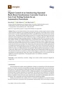
Vref(k)
The aim of this paper is to describe the sampled data modeling of a switching regulator and the practical implementation of a digital compensator on an 8 bit microcontroller. The major blocks comprising a digital control loop are described and their transfer functions are derived. Practical issues involved in digital control using low cost 8 bit microcontrollers are discussed and results are presented. Modeling of switching regulators in continuous time domain is a well established discipline. Introduced by S. Cuk [1], the averaging approach for switching regulator modeling is a well known and widely popular technique. In this approach, the non-linear switching waveforms are averaged over one switching period thereby removing switching ripple and associated non-linearity. This is justified as in a well designed converter the switching ripple is small as compared to dc quantities. Small signal models can then be derived and used for control system design. The advantages of this approach are its simplicity and ease of use. Moreover, analog control design tools can be used for designing control systems. However, these models are accurate up to half of the switching frequency. Discreet time modeling of switching regulators was introduced by J. Packard [2]. In this approach, instead of averaging, converter waveforms are described at the instant of sampling [9]. This captures the behavior of converter at the sampling instant which is then extended over entire switching period. This modeling results in exact small signal models of switching regulators which can be used to design control systems using MATLAB. These models are accurate throughout the frequency range. However such models suffer from the complexity of the results as well as lack of close form results. Sampled data modeling approach introduced by A.R. Brown [3] combines the simplicity of average modeling approach with the accuracy of discreet time modeling technique. The entire system is modeled in continuous domain using conventional Laplace transform transfer functions. The delay associated with the digital control loops is modeling using a single delay block.
+
Error(k)
Compensator Block Gc(s)
U(k)
PWM Generator Kpwm(s)
d(k)
Delay Block e-st
d(t)
Vout(t) Gvd(s)
Vsense(k) ADC and Sensing Block Kadc(s)
Fig. 1. Sampled Data Model This retains the closed form results nature of the model and also incorporates the physical delays associated with the practical systems. In this work, a sampled data model of a buck converter is used to model the system and select compensator. The efficacy of the compensator designed is validated through MATLAB simulations. The digital loop is closed around an 8 bit microcontroller from ST Micro. The aim of this work is to provide an easy to understand derivation of sampled data model as well as demonstrate the capability of an 8 bit system to control a switching converter with acceptable performance for a given application. The paper is presented in following way: section 2 and 3 provide derivation of average circuit modeling approach and state space averaging approach for a special case of buck converter including inductor dc resistance and capacitor esr. It is assumed that the converter operates in continuous conduction mode. Section 4 provides description of transfer functions for various building blocks of a digital control loop. Section 5 provides simulation results of compensator designed in MATLAB as well as practical implementation details. Section 6 describes potential applications of this converter.
2. Average Circuit Modeling We begin with the basic buck converter schematic as shown below. Note that inductor dc resistance and capacitor esr are ignored initially and will be incorporated later. Non-Linear Switching Portion
MOSFET
+
L Vg(t)
C
R
V (t)
Diode
-
_______________________ Muhammad Umar Abbasi is currently working as Assistant Manager (Electrical) at Power System Labs, Satellite Research and Development Center (SRDC-L), SUPARCO, Pakistan.
INTERNATIONAL JOURNAL OF SCIENTIFIC & TECHNOLOGY RESEARCH VOLUME 6, ISSUE 04, APRIL 2017
The aim of the modeling is to replace the non linear switching part of the converter with linear circuit elements so that the circuit can be solved for transfer functions using linear circuit analysis tools. The buck converter in continuous conduction mode operates periodically in two states; subinterval one in which MOSFET switch is ON and diode is off; subinterval two in which MOSFET switch is OFF and diode is ON. In first step, both these subintervals along with the equations describing inductor current and output voltage are shown: MOSFET short L + iL (t) +VL (t)ig (t)
Vg(t)
C Diode open
R
V (t)
(1) (2)
L +VL (t)C
iC (t)
+
iC (t ) C
ig (t ) 0
diL (t ) dt dV (t ) dt
V (t )
iL (t ) Ts
V (t ) Ts
dt ig (t ) Ts iL(t ) Ts * d (t )
(10)
R
(11)
The above equations describe the large signal model of the buck converter. In order to derive the small signal model of the buck converter, a steady state solution is assumed to exist (Vg, V, I, D) and following variables are perturbed and linearized:
(12)
Where the small perturbation in x(t) is denoted as x̂(t) and it is further assumed in accordance with small ripple approximation that: x̂(t)