An example product line architecture: Digital Library Projects Ebru Dincel1 Nenad Medvidovic1 André van der Hoek2 Computer Science Department University of Southern California Los Angeles, CA 90089-0781 USA {edincel, neno}@usc.edu 1
2
Institute for Software Research University of California, Irvine Irvine, CA 92697-3425 USA
[email protected]
1. Introduction Software application families and their accompanying architectures (also referred to as product line architectures or PLAs) are a promising area in which the potential of software component reuse can be fully realized. Evolving such application families necessitates making informed architectural decisions. Among industry and research communities, it is recognized that software metrics can provide guidance during the making of such decisions. In an earlier paper [3], we introduced metrics that are specifically geared to assess product line architectures and help in maintaining their quality. Below is a more elaborate definition of the metrics. The basic building blocks of our metrics are the concepts of Provided Service Utilization (PSU) and Required Service Utilization (RSU), as defined on a per-component basis. PSU and RSU of a component X are defined as follows: PSUX =
Pactual Ptotal
RSUX =
Ractual Rtotal
In these formulas, Pactual is the number of services provided by component X that are actually used by other components in the architecture, Ptotal is the total number of services provided by component X. Ractual and Rtotal have analogous meanings for required services. In addition to assessing each individual component, it is useful to analyze an architecture as a whole. To this end, the Compound PSU (CPSU) and Compound RSU (CRSU) are defined as follows: n
CPSU =
i ∑ Pactual i =1 n
∑P i =1
i total
n
CRSU =
∑R i =1 n
i actual
∑R i =1
i total
1
Pactual, Ptotal, Ractual, and Rtotal are defined as in PSU and RSU, while n is the number of components in the architecture. In order to match a provided with a required service, we use “name matching”. This type of match requires only names of services to match. PLA's tend to be proprietary and are typically not described in literature. In those few cases where they are [5], no architectural descriptions are given and insufficient detail is supplied to even reconstruct such descriptions. For this reason, in order to demonstrate our experiences with the metrics, we have applied them on a digital library application product line developed in the context of a long-running graduate course at USC. CS577 is a two-semester project course for computer science graduate students at USC. Assigned teams develop a variety of digital library applications for a real client, the Library Information Services Division (ISD) at USC. These projects are characterized by continuous interactions with their (real) customers, guidance by up to four software engineering instructors at any given time, and a well established methodology [1]. The adherence to the customer and instructor requirements is ensured via periodic reviews. After the products are delivered to ISD, they are maintained by paid professional programmers. Even though the course instructors treat the projects as belonging to several distinct product lines and conduct the course with an extensive focus on software architectures, again, no formal PLA description existed for these product lines. However, we were given full access to the course’s resources, including its instructors, customers, and project documentation. To date, about sixty such applications have been developed, comprising several distinct application families. Based on this information, we were able to select a family (consisting of five members) of applications, and construct and verify an explicit model of the PLA for that family. There is not any standard naming convention or a formal PLA description used in the course. Since the projects are developed by different teams, the components are renamed differently even though they implement similar behavior. Therefore, we have mapped most of the component names as documented to their more common counterparts. Although the behavior of the components may change slightly from project to project, Table 1 is an effort to standardize these component names as an initial step to find commonality among the projects. The first column lists the component names, whereas the second column lists the component descriptions. Table 1 Component names and descriptions NAME
DESCRIPTION
ACCOUNT MANAGER
Manages accounts.
ADMIN INTERFACE
An interface mainly for privileged users (mainly administrators) to set up critical information about the data stored the repository, or in secondary storage (AUX REPOSITORY). Some projects only support off-line administrative functions.
AUTHENTICATOR
Authenticates privileged users.
AUX REPOSITORY
Stores other project related data.
MEDIA UTILITIES
COTS component with image processing utilities.
REPOSITORY
Image Archive, mainly binary objects.
SEARCH MANAGER
Queries the data storage (e.g. REPOSITORY, AUXREPOSITORY).
UPDATE MANAGER
Updates the data storage (e.g. REPOSITORY, AUXREPOSITORY).
USER INTERFACE
An interface mainly for day-to-day users mainly for query/display purposes.
2
2. Project Architectures We used five projects from CS577 as the basis of our study. We refer to their architectures as “project architectures”. The following subsections further detail our experiences with these projects. Unfortunately, not all of the cs577 project archive materials are publicly accessible. However, there is an ongoing effort to set up the Project Archives [4]. We have represented only a fraction of the archive material that is of interest for the discussions in this report. We selected five projects based on the availability of the archive material. For each project, we have provided the high level architectural models as identified by the team. Then, we have mapped the component names as documented to their more common counterparts as introduced in Table 1. In a few cases, we have updated the component model with extra components. Although these components were not identified in the component model, they were discussed in other type of architectural models. Otherwise, we were faithful to the model as provided in the documents. Based on the update, we have drawn an updated component diagram. Finally, for each component in the diagram, we have provided the component specifications for provided and required services. 2.1.1 Project Architecture 1
“Hispanic Digital Archive (HDA)” is a project developed by team 5 in Fall 1998. Below is the project description. “We will provide a system to access the large number of Boeckmann Center materials in an attractive and simple fashion; concurrently the collections will be organized into a unified cataloging system within the archive. Access will take the form of searching the digital archive resulting in meaningful and salient search results as well as viewing items in the archive. Access also includes browsing information about the Boeckmann Center, the collections, and a limited subset of the archive, in addition to requesting materials, offering feedback, and receiving help. The system will also allow quick and easy entry and maintenance of the material information by inexperienced library personnel after an authentication process. Administration users will also have help available. The librarian will have access and authority to ensure the integrity of the data before entry into the archive. The Hispanic Digital Archive will be the portal to the Boeckmann Center collections. The collection materials are represented in the HDA. The users will view items and search for items. The operators and librarians will maintain the HDA. “ The following are identified as components by the team: 1. Hispanic_Digital_Archive (A vast collection of digitized Hispanic material being managed by the Boeckmann Center of the University of Southern California) 2. HDA_Material (Digitized information on Hispanic material of the Boeckmann Center) 3. HDA_Administrator (A person who performs management and maintenance operations on the archive and its items.) 4. HDA_Patron_Interface (A person who is interested in using the Hispanic literature.)
3
Figure 1 shows the identified component interactions. At the highest level, the operations that need to be supported by the architecture can be summarized into three groups: •
Authorize and Administrate (by HDA_Administrator)
•
Request (by HDA_Patron Interface and HDA_Administrator)
HDA_Patron_ Interface
queries Hispanic_Digital _Archive
HDA_Material stores
updates
HDA_ Administrator
Figure 1 Component diagram
A further look at the architectural documents indicates the existence of a few other components as well. One of them is SEARCH MANAGER. This component processes the query requests from the HDA_Patron Interface and sends back the requested Items and Images. The other one is MEDIA UTILITIES. It is a COTS product that provides common image library utilities. We have mapped the component names to their more common counterparts as discussed in Table 1 (see Table 2). Figure 2 is a more faithful representation of the architecture. Table 3 is the recovered and simplified API for this project. The first column is the component name. The second and third columns represent the service elements; provided and required service elements namely. Table 2 Component name mapping OLD NAME
NEW NAME
Hispanic_Digital_Archive
REPOSITORY
HDA_Material
AUX REPOSITORY
HDA_Administrator
ADMIN INTERFACE
HDA_Patron Interface
USER INTERFACE
4
Figure 2 Updated component diagram
Table 3 Hispanic Digital Archive component specifications NAME
PROV
REQ addImage
ADMIN INTERFACE
addItemType addOperator addItem addWatermarkImage addFieldOption deleteImage deleteItemType deleteItem deleteFieldOption deleteOperator modifyOperator modifyItem getItem convertImage AUX REPOSITORY
setItemInfo setImageInfo getItemInfo getImageInfo
MEDIA UTILITIES
panImage
getImage
zoomImage
setImage
cropImage blurImage convertImage
5
compressImage manipulateImage thumbnailImage REPOSITORY
getImage
setItemInfo
getItem
setImageInfo
retrieveItemInfo
getItemInfo
retrieveImageInfo
getImageInfo
retrieveItem retrieveImage addImage addItemType addItem addWatermarkImage addFieldOption deleteImage deleteItemType deleteItem deleteFieldOption modifyItem SEARCH MANAGER
query
retrieveItemInfo retrieveImageInfo retrieveItem retrieveImage
USER INTERFACE
query retrieveItemInfo retrieveImage
2.2 Project Architecture 2 “Pathology Image Search Engine (PISE)” is a project developed by team 3 in Spring 2001. Below is the project description. “As part of the Medical School curriculum, students study the pathological basis of disease and need access to a large variety of pathology slides and images. Many of these have been digitized and made available through the Medical School’s Web page. We would like to have the capability of searching through a selected set of Web pages for a particular type of pathologic image (i.e. lung tissue infected with cytomegalovirus) and returning any related images. This project could be further enhanced by utilizing some of the tools developed and made available for free from the National Library of Medicine.” The following are identified as components by the team: 1. User Search Interface (Web Interface used by the Med Web user to initiate search for Pathology Images)
6
2. Pathology Image Link Database (A collection of Links and Associated text of a Pathology Slide) 3. Administrator Interface (Administrator’s interface with the system software) 4. Link Database Search Manager (The component which is in charge of managing the search of Links in the Link Database) 5. Link Database Update Manager (The component which is in charge of updating the Link Database and searching the given Websites) Figure 3 shows the identified component interactions. At the highest level, the operations that need to be supported by the architecture can be summarized into two groups: •
Link Retrieval
•
Link Maintenance
U s e r S e a rc h In t e rfa c e
0..* D is p la y R e s u lt s
P ro vid e In p u t s
L in k D a t a b a s e S e a rc h M a n a g e r
1 .. n
0..*
G i ve R e s u lt s
S e a rc h
1
P a t h o lo g y Im a g e L in k D a t a b a s e 0..*
C re a t e
1 A d m in is t ra t or In t e rf a c e
1
P ro vid e W e b s it e L is t 1..n
L in k D a t a b a s e U pdate M anager
Figure 3 Component diagram
A better look at the architectural documents indicates the existence of another component as well. UMLS Database component is a medical thesaurus database which will serve as providing synonyms for the unknown words as specified by the user. We have mapped the component names to their more common counterparts as discussed in Table 1 (see Table 4). Figure 4 is a more faithful representation of the architecture. Table 5 is the recovered and simplified component specifications for this project. The first column is the component name. The second and third columns represent the service elements; provided and required service elements namely. Table 4 Component name mapping OLD NAME
NEW NAME
Pathology Image Link Database
REPOSITORY
UMLS Database
AUX REPOSITORY
Administrator Interface
ADMIN INTERFACE
7
User Search Interface
USER INTERFACE
Link Database Search Manager
SEARCH MANAGER
Link Database Update Manager
UPDATE MANAGER
Figure 4 Updated component diagram Table 5 Pathology Image Search Engine component specifications NAME
PROV
REQ checkPageValidity
ADMIN INTERFACE
getPathologyLink getPathologyLinkBySiteName getSiteNameByMainLink updatePathologyLink AUX REPOSITORY
getSynonymOrgan getSynonymDisease getSynonymPrep getSynonymStain getSynonym retrieveSynonymInfo
REPOSITORY
setTableName getPathologyLink getPathologyLinkBySiteName
8
addPathologyLink getMainSiteAndLink removePathologyLinkbySiteLink getSiteNameByMainLink retrieveLinkInfo SEARCH MANAGER
query
retrieveSynonymInfo retrieveLinkInfo
UPDATE MANAGER
checkPageValidity
setTableName
updatePathologyLink
getPathologyLink getPathologyLinkBySiteName addPathologyLink getMainSiteAndLink removePathologyLinkbySiteLink getSiteNameByMainLink
USER INTERFACE
query getSynonymOrgan getSynonymDisease getSynonymPrep getSynonymStain getSynonym
2.3 Project Architecture 3 “World War I Record Enhancement (WWIRE)” is a project developed by team 13 in Spring 1999. Below is the project description. “The Von KleinSmid Center Library (VKC Library) is an integrated part of the University of Southern California’s library system. It contains an extensive collection of books, publications, journals, international documents, encyclopedias etc., in the areas of political science, international relations, public administration, urban planning and related subjects. The VKC Library holds a collection of approximately 1200 volumes related to the First World War. Some of these books are large in size and occupy considerable storage space. Like many other libraries, the VKC Library is currently running out of physical space to store its collection. Consequently the VKC Library would like to archive some of its less used materials into storage facilities where they can be warehoused more economically, beginning with the library’s World War I collection. However, the library would still like to make the materials as accessible to its users as much as possible. Ideally, the library users should be able to search for the material and use the results of the search to determine whether that material is worth obtaining and borrowing.” The following are identified as components by the team: 1. WWI Book Information User Search System (The search system interfaces between the user and the database that he/she intends to search through. It 9
translates queries posed by the user into searches on the database and outputs appropriate results.) 2. WWI Book Information Administrator System (A system via which the administrator will be able to maintain the WWI Book Information Archive as well as provide security for the WWI Book Information Archive.) 3. WWI Book Information Archive (The Archive contains electronic information about WWI Books in the Von Klein Library that have been removed from the stacks for lack of space.) 4. WWI Book Information (This component contains information pertaining to WWI Books that have been archived.) 5. WWI Archive Administrator (The Administrator handles the administration of the database such as inclusion of new contents or updating of old. Security issues involved in authenticating the administrator are part of the interaction.) Figure 5 shows the identified component interactions. At the highest level, the operations in the architecture can be summarized into two groups: •
WWI Book Information User Search System Behavior
•
WWI Book Information Administration System Behavior
WWI Book Information
WWI Book Information Administrator system Stores Performs operations on WWI Book Information Archive
Queries
WWI Book Information User Search system
Used for authentication
Stores Information About WWI Archive Administrator
Figure 5 Component diagram
A better look at the architectural documents indicates the existence of another component as well. That component is the AUTHENTICATOR which is involved in authenticating the Administrator. We have mapped the component names to their more common counterparts as discussed in Table 1 (see Table 6). Figure 6 is a more faithful representation of the architecture. 10
Table 7 is the recovered and simplified component specifications for this project. The first column is the component name. The second and third columns represent the service elements; provided and required service elements namely. Table 6 Component name mappings OLD NAME
NEW NAME
WWI Book Information Archive
REPOSITORY
WWI Book Information
AUX REPOSITORY
WWI Book Information Administrator System
ADMIN INTERFACE
WWI Book Information User Search System
USER INTERFACE, SEARCH MANAGER
Authenticator
AUTHENTICATOR
Figure 6 Updated component diagram Table 7 World War I Record Enhancement component specifications NAME
PROV
REQ
ADMIN INTERFACE
readUserpwd
addBookInfo modifyBookInfo deleteBookInfo generateReport authenticateAdmin setAdminInfo
AUTHENTICATOR
authenticateAdmin
getAdminInfo
addBookInfo
readUserpwd
modifyBookInfo deleteBookInfo generateReport AUXREPOSITORY
setImage
11
setTitle getImage getTitle REPOSITORY
setAdminInfo
setImage
addBookInfo
setTitle
modifyBookInfo
getImage
deleteBookInfo
getTitle
getBookInfo getAdminInfo SEARCH MANAGER
query
USER INTERFACE
getBookInfo
query
2.4 Project Architecture 4 “Viewing Utility for Oversized Scanner Paper Objects” is a project developed by team 2 in Spring 2000. Below is the project description. “Through a partnership with the Huntington Library, USC has scanned the Huntington's complete sets of El Clamor Publico and the Los Angeles Star, the first Spanish and English language newspapers in LA. The file sizes for the scans range from 30MB to 85MB, and in total they occupy approximately a terabyte of disk-space. The first part of the project will involve outlining an ideal viewer for the scans. Next, students will research existing methods of achieving lossless compression and viewability of oversized scanned objects via the internet. If an appropriate solution for viewing does not already exist commercially, students will define the characteristics and components necessary to build a viewer.” The following are identified as components by the team: 1. Web User Interface (The client interaction using the HTML page with the system) 2. Image Web Server(To store the images, compressed form) 3. Image Utilities (COTS tool to be used for viewing , compressing and such image utilities) 4. ISD's BRS System (search engine) 5. Permanent CD Storage Figure 7 shows the component interactions. At the highest level, the operations in the architecture can be summarized into two groups: 12
•
User behavior
•
Maintainer behavior
We have mapped the component names to their more common counterparts for as discussed in Table 1(see Table 8). Figure 8 is a more faithful representation of the architecture. Table 9 is the recovered and simplified component specifications for this project. The first column is the component name. The second and third columns represent the service elements; provided and required service elements namely. Image Web Server
Web User Interface
Image Archive
Records Found
display
Metadata Search Results
(from Enterprise Model )
(from Enterprise Model )
select request MrSID Java Client (from Enterprise Model )
display
Compress Image (from Enterprise Model )
made into
Browser (from Enterprise Model )
Image (from Enterprise Model )
+left_side
+right_side
Thumbnail Image (from Enterprise Model )
retrieves captured by
captured by Image Utilities
(from Enterprise Model )
+back_page
+front_page Compression Utility
Thumbnail Utility
Issue
(from Enterprise Model )
(from Enterprise Model )
(from Enterprise Model )
ISD BRS System
(from Enterprise Model )
1..*
searches
BRS Search Engine
Newspaper (from Enterprise Model )
Metadata
(from Enterprise Model )
1
has an
Permanent CD Storage
describes image in
Description
MrSID Image Server
CD Image (from Enterprise Model )
stored on
CD-ROM (from Enterprise Model )
BRS
(from Enterprise Model )
(from Enterprise Model )
1
1
Figure 7 Component diagram Table 8 Component name mappings OLD NAME
NEW NAME
Image Archive
REPOSITORY
Newspaper
AUX REPOSITORY
Web User Interface
USER INTERFACE
Image Utilities
MEDIA UTILITIES
ISD's BRS System
SEARCH MANAGER
13
Figure 8 Updated component diagram Table 9 Viewing Utility for Oversized Scanner Paper Objects component specifications NAME
PROV
AUX REPOSITORY
getNewsPaperList
REQ
getMetaData setMetaData
MEDIA UTILITIES
panImage
getImage
zoomImage
setImage
cropImage blurImage convertImage compressImage manipulateImage thumbnailImage REPOSITORY
getImage setImage
SEARCH MANAGER
query
getNewsPaperList getMetaData
USER INTERFACE
query getImage compressImage panImage
14
zoomImage setMetaData
2.5 Project Architecture 5 “Access and Display Archive Image Composer” is a project developed by team 14 in Spring 2001. Below is the project description. “This project requires the development of a client/user interface for its collection of digital images and text metadata. The 1500 digital images the library possesses currently are stored on a university server and the descriptive metadata is stored in File Maker Pro on computers housed in the Slide Library. The client would like to make the images and associated text data available via the Internet to faculty and students who have access through the USC domain name. The purpose of the access is to provide the capability to prepare and save classroom presentations using this material. A system is needed which can retrieve images on searchable criteria for the USC community. The proposed system is required as currently there is no web searchable software that utilizes the image data contained in the UNIX server. The proposed system would make the local image library searchable and also would enable the faculty to use the slide library effectively. This system would be very efficient in terms of query accuracy. “ The following are identified as components by the team: 1. SIL Web Interface (The client side web based interface) 2. FileMakerPro (COTS product used for Metadata storage and searching of images) 3. Image Archive (All images stored on a UNIX server) 4. MrSid (Performs different operations on images such as zooming and panning) 5. UserFolder (Images can be stored in folders. The folders can be on the client or the server side but the access is limited by privilege. 6. ImageHandler (Handles all the manipulations on the images) Figure 9 shows the component interactions. We have mapped the component to their more common as discussed in Table 1 (see Table 10). Figure 10 is a more faithful representation of the architecture. Table 11 is the recovered and simplified component specifications for this project. The first column is the component name. The second and third columns represent the service elements; provided and required service elements namely.
15
Use rFo ld er hand le s cre atio n/upd atio n
communicates through S IL W eb Interface
Image Handler
sea rching
FileMakerPro
viewing > MrSid retrieve images...
< > Ima ge Archive
Figure 9 Component diagram Table 10 Component name mappings OLD NAME
NEW NAME
Image Archive
REPOSITORY
User Folder
AUX REPOSITORY
SIL User Interface
USER INTERFACE
Mr. Sid
MEDIA UTILITIES
File Maker Pro
SEARCH MANAGER
Figure 10 Updated component diagram 16
Table 11 Access and Display Image Composer component specifications NAME
PROV
REQ
AUX REPOSITORY
getMetaData getgroupFolders
MEDIA UTILITIES
panImage
getImage
zoomImage
setImage
cropImage blurImage convertImage compressImage manipulateImage thumbnailImage REPOSITORY
setImage getImage
SEARCH MANAGER
querybyKeyword
getMetaData
querybyCriteria
getgroupFolders
querybyKeywordAndCriteria querybyKeyword
USER INTERFACE
querybyCriteria querybyKeywordAndCriteria getImage thumbnailImage cropImage manipulateImage setImage
3. PLA Summary Table 12 summarizes the metrics values for the project architectures (PA1-5). The values inside the parentheses indicate the PSU and RSU values respectively. N/A denotes that the metrics are not applicable for that component, i.e. the component does not exist in that architecture. Ø denotes that there is no service defined, whereas 0 denotes that none of the defined services are utilized. The last two rows indicate the CPSU and CRSU values for these projects. Table 12 Metrics' values for project architectures PA1
PA2
PA3
PA4
PA5
ADMIN INTERFACE
(Ø, 0.8)
(Ø, 1)
(1, 1)
N/A
N/A
AUTHENTICATOR
N/A
N/A
(1, 1)
N/A
N/A
17
AUX REPOSITORY
(1, Ø)
(1, Ø)
(1, Ø)
(1, Ø)
(1, Ø)
MEDIA UTILITIES
(0.1, 1)
N/A
N/A
(0.4, 1)
(0.4, 1)
REPOSITORY
(1, 1)
(1, Ø)
(1, 1)
(1, Ø)
(1, Ø)
SEARCH MANAGER
(1, 1)
(1, 1)
(1, 1)
(1, 1)
(1, 1)
UPDATE MANAGER
N/A
(1, 1)
N/A
N/A
N/A
USER INTERFACE
(Ø, 1)
(Ø, 1)
(Ø, 1)
(Ø, 1)
(Ø, 1)
CPSU
0.76
1
1
0.64
0.66
CRSU
0.89
1
1
1
1
Figure 11 shows the current PLA as it currently is. The descriptions of these components are provided in Table 1. As seen from the figure, MEDIA UTILITIES is a common asset (shared among all projects). REPOSITORY, AUX REPOSITORY, SEARCH MANAGER, USER INTERFACE components are variant; ADMIN INTERFACE is an optional variant; and AUTHENTICATOR, UPDATE MANAGER components are optional.
Figure 11 Initial PLA
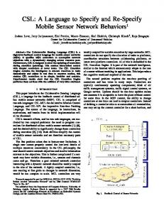
Figure 12 shows the PSU and RSU spans of these components as defined in project architectures PA1-5. The span does not necessarily have 5 points since N/A and Ø values are not plotted. 18
Figure 12 PSU and RSU spans for project architectures
19
3.1 Observations on project architectures While CS577 focuses on product lines, it does so in an informal manner. Graphical depictions of the various PLAs are available, but explicit architectural descriptions are lacking. To study the structure of the digital library PLA, we therefore reverse engineered its description by studying project documentation, interviewing course instructors, and combining individual architectures into one single PLA. In this process, we did not always have access to the complete interfaces of the COTS components used. In such cases, we provided approximations of those components’ interfaces in order to still be able to apply our metrics. As seen in Figure 12, most spans exhibit a set of high values indicating that the majority of the PLA has good structural quality. Note that some of the spans have fewer than five values, since the respective provided or required interfaces are only connected to other components in a few of the products. Figure 12 also indicates the presence of some potential problems. The first problem is highlighted by the RSU span of the ADMIN INTERFACE component, which shows that in one product, one fourth of the required services of this component are not met by the rest of the PLA. A further investigation reveals that ADMIN INTERFACE is a variant component and that one of the variants requires some account management services. To address this problem, we examined several alternatives. In the below discussions, we only show the values for three project architectures since ADMIN INTERFACE component is only used in those projects. •
Remove the account management requirements from the ADMIN INTERFACE variant. The system might have been required to provide account management services initially, but later this might have changed. This alternative means that the system will not provide account management services anymore. The values presented in Table 13 approximately result in 4% increase in average CRSU and 8% increase in RSU of ADMIN INTERFACE component.
Table 13 Results of the first alternative CPSU
PA1
PA2
PA3
Before
0.76
1
1
After
0.76
1
1
CRSU
PA1
PA2
PA3
Before
0.89
1
1
After
1
1
1
RSU (ADMIN INTERFACE)
PA1
PA2
PA3
Before
0.8
1
1
After
1
1
1
•
Add an optional account management component, ACCOUNT MANAGER. Since the system identifies an ADMIN INTERFACE component and such components are generally in charge of account management services, the system might in fact be in need of such services. The values presented in Table 14 approximately result in
20
1% increase in average CPSU, 4% increase in average CRSU, and 8% increase in RSU of ADMIN INTERFACE component. Table 14 Results of the second alternative CPSU
PA1
PA2
PA3
Before
0.76
1
1
After
0.78
1
1
CRSU
PA1
PA2
PA3
Before
0.89
1
1
After
1
1
1
RSU (ADMIN INTERFACE)
PA1
PA2
PA3
Before
0.8
1
1
After
1
1
1
•
Add a required account management component, ACCOUNT MANAGER. The values presented in Table 15 approximately result in 12% decrease in average CPSU, 3% increase in average CRSU, and 8% increase in RSU of ADMIN INTERFACE component.
Table 15 Results of the third alternative CPSU
PA1
PA2
PA3
PA4
PA5
Before
0.76
1
1
0.64
0.66
After
0.78
0.85
0.85
0.53
0.55
CRSU
PA1
PA2
PA3
PA4
PA5
Before
0.89
1
1
1
1
After
1
1
1
1
1
RSU (ADMIN INTERFACE)
PA1
PA2
PA3
PA4
PA5
Before
0.8
1
1
N/A
N/A
After
1
1
1
N/A
N/A
Calculating our metrics for each case reveals that the second alternative is the best. A further investigation shows that the first alternative, removing the account management requirements from the ADMIN INTERFACE variant is not consistent with the information provided in the project’s (PA1’s) architectural documentation. Therefore, it is not a feasible alternative. Since our metrics do not take any semantic information into account, it would not be able to catch such cases. Intuitively, the second alternative is indeed the best structural solution since it matches up services as needed. Making ACCOUNT MANAGER a required component, as proposed by the third alternative, results in the lowest values. This result makes sense, since the account management requirements are needed only in one project. Hence, making it a required component such that it is shared by all of the projects decreases the utilization in those projects that do not need these 21
services. Figure 13 shows the new architecture after making the changes as proposed by the second alternative. A second potential problem is highlighted by the PSU span of the MEDIA UTILITIES component. The span is wide and the individual values are very low. A further investigation reveals that the component exposes two classes of services: (1) displaying an image and (2) manipulating an image. Moreover, different products always use one class of services only, never both. To address the resulting unnecessary bloat of the individual products, we considered three alternatives. In the below discussions, we only show the values for three project architectures since MEDIA UTILITIES component is only used in those projects. •
Split the MEDIA UTILITIES component into two variants. Each variant would implement one class of services as discussed above. The values presented in Table 16 approximately result in 30% increase in average CPSU, and 108% increase in PSU of MEDIA UTILITIES component.
Table 16 Results of the first alternative CPSU
PA1
PA4
PA5
Before
0.76
0.64
0.66
After
0.88
0.9
0.9
CRSU
PA1
PA4
PA5
Before
0.89
1
1
After
0.89
1
1
PSU (MEDIA UTILITIES)
PA1
PA4
PA5
Before
0.1
0.4
0.4
After
0.25
0.75
0.75
•
Design a customized variant for each product. This alternative is very similar in nature to the first alternative. However, this alternative is a finer grained option as compared to the first, where customization aligns the necessary functionality in each product perfectly. The values are presented in Table 17. Even though our assessment of the first and second alternatives indicated approximately 30% increases in average CPSU values, carrying out these two alternatives would be impossible since MEDIA UTILITIES is a COTS component for which source code is not available.
Table 17 Results of the second alternative CPSU
PA1
PA4
PA5
Before
0.76
0.64
0.66
After
1
1
1
CRSU
PA1
PA4
PA5
Before
0.89
1
1
22
After
0.89
1
1
PSU (MEDIA UTILITIES)
PA1
PA4
PA5
Before
0.1
0.4
0.4
After
1
1
1
•
Keep the MEDIA UTILITIES component unchanged. This alternative obviously does not change the metrics values since there is no structural change (see Table 18).
Table 18 Results of the third alternative CPSU
PA1
PA4
PA5
Before
0.76
0.64
0.66
After
0.76
0.64
0.66
CRSU
PA1
PA4
PA5
Before
0.89
1
1
After
0.89
1
1
PSU (MEDIA UTILITIES)
PA1
PA4
PA5
Before
0.1
0.4
0.4
After
0.1
0.4
0.4
Our metrics indicate higher values for the first two alternatives, especially for the second one. However, in this case, reuse considerations outweigh structural quality, since redeveloping the component from scratch is costly. Hence, we chose to apply the third alternative. Overall, the suggestions for these two problems result in the CPSU values increasing by 1% and in CRSU values increasing by 3% in average(see Table 19). Table 20 shows the final component specifications and Figure 13 shows the final PLA. Table 19 Final results CPSU
PA1
PA2
PA3
PA4
PA5
Before
0.76
1
1
0.64
0.66
After
0.78
1
1
0.64
0.66
CRSU
PA1
PA2
PA3
PA4
PA5
Before
0.89
1
1
1
1
After
1
1
1
1
1
Table 20 Final component specifications NAME
PROV
ACCOUNT MANAGER
addOperator
REQ
deleteOperator
23
modifyOperator addImage
ADMIN INTERFACE (V1)
addItemType addOperator addItem addWatermarkImage addFieldOption deleteImage deleteItemType deleteItem deleteFieldOption deleteOperator modifyOperator modifyItem getItem convertImage checkPageValidity
ADMIN INTERFACE (V2)
getPathologyLink getPathologyLinkBySiteName getSiteNameByMainLink updatePathologyLink ADMIN INTERFACE (V3)
readUserpwd
addBookInfo modifyBookInfo deleteBookInfo generateReport authenticateAdmin setAdminInfo
AUTHENTICATOR
authenticateAdmin
getAdminInfo
addBookInfo
readUserpwd
modifyBookInfo deleteBookInfo generateReport AUX REPOSITORY (V1)
setItemInfo setImageInfo getItemInfo getImageInfo
AUX REPOSITORY (V2)
getSynonymOrgan getSynonymDisease getSynonymPrep getSynonymStain getSynonym retrieveSynonymInfo
24
AUX REPOSITORY (V3)
setImage setTitle getImage getTitle
AUX REPOSITORY (V4)
getNewsPaperList getMetaData setMetaData
AUX REPOSITORY (V5)
getMetaData getgroupFolders
MEDIA UTILITIES
panImage
getImage
zoomImage
setImage
cropImage blurImage convertImage compressImage manipulateImage thumbnailImage REPOSITORY (V1)
getImage
setItemInfo
getItem
setImageInfo
retrieveItemInfo
getItemInfo
retrieveImageInfo
getImageInfo
retrieveItem retrieveImage addImage addItemType addItem addWatermarkImage addFieldOption deleteImage deleteItemType deleteItem deleteFieldOption modifyItem REPOSITORY (V2)
setTableName getPathologyLink getPathologyLinkBySiteName addPathologyLink getMainSiteAndLink removePathologyLinkbySiteLink getSiteNameByMainLink retrieveLinkInfo
REPOSITORY (V3)
setAdminInfo
setImage
25
addBookInfo
setTitle
modifyBookInfo
getImage
deleteBookInfo
getTitle
getBookInfo getAdminInfo REPOSITORY (V4)
getImage setImage
SEARCH MANAGER (V1)
query
retrieveItemInfo retrieveImageInfo retrieveItem retrieveImage
SEARCH MANAGER (V2)
query
retrieveSynonymInfo retrieveLinkInfo
SEARCH MANAGER (V3)
query
getBookInfo
SEARCH MANAGER (V4)
query
getNewsPaperList getMetaData
SEARCH MANAGER (V5)
querybyKeyword
getMetaData
querybyCriteria
getgroupFolders
querybyKeywordAndCriteria UPDATE MANAGER
checkPageValidity
setTableName
updatePathologyLink
getPathologyLink getPathologyLinkBySiteName addPathologyLink getMainSiteAndLink removePathologyLinkbySiteLink getSiteNameByMainLink
USER INTERFACE (V1)
query retrieveItemInfo retrieveImage
USER INTERFACE (V2)
query getSynonymOrgan getSynonymDisease getSynonymPrep getSynonymStain getSynonym
USER INTERFACE (V3)
query
USER INTERFACE (V4)
query getImage compressImage panImage zoomImage
26
setMetaData USER INTERFACE (V5)
querybyKeyword querybyCriteria querybyKeywordAndCriteria getImage thumbnailImage cropImage manipulateImage setImage
Figure 13 Final PLA
4. Conclusion A product line must involve three essential activities: core asset development, product development using the core assets, both under the control of technical and organizational management [2]. A successful product line needs an understanding of the commonalities, variation, future vision, inventory of existing assets and overall approach for realizing the core assets.
27
The work described in this report attempts to set up an inventory of existing assets (only for a limited set of projects) with the help of the service utilization metrics. These metrics represent an important step in further maturing product line architecture as a discipline. The metrics provide a solid foundation and accompanying method that is intended not only to identify potential structural problems in a PLA, but also to evaluate different solutions to such problems. As such, the metrics complement design reviews and an architect’s intuition with a previously unavailable mechanism to assess the structure of PLAs. Of course, other influences, such as cost, performance, or reusability, may lead to a choice of a less-than-optimal structural solution. Nonetheless, our metrics add one, critical, input datum to this selection process, namely the structural soundness of a PLA. In addition to the data/experience collection methods such as utilization metrics, we have identified the following action items as a first step to build a solid basis for a successful PLA. 1. early standardization efforts 2. adoption of a formal architecture description language 3. a common media to advertise interfaces and components 4. emphasis and encouragement on reusability 5. feedback from domain analysis Acknowledgements This research is supported by the National Science Foundation under Grant Numbers CCR-9985441 and CCR-0093489. Effort also sponsored by the Defense Advanced Research Projects Agency, Rome Laboratory, Air Force Materiel Command, USAF under agreement numbers F30602-00-2-0615 and F30602-00-2-0599. The U.S. Government is authorized to reproduce and distribute reprints for governmental purposes notwithstanding any copyright annotation thereon. The views and conclusions contained herein are those of the authors and should not be interpreted as necessarily representing the official policies or endorsements, either expressed or implied, of the Defense Advanced Research Projects Agency, Rome Laboratory or the U.S. Government. Effort also supported in part by Xerox. References [1]Boehm, B.e.a. The MBASE Life Cycle Architecture Milestones Package: No Architecture Is An Island., Proceedings of the First Working International Conference on Software Architecture. 1999. p. 511-528. [2]Clements, P., Northrop, L. Software Product Lines: Practices and Patterns, ed. A. Wesley. 2002. 29-54. [3]Dincel, E., Medvidovic, N. , van der Hoek, A. Measuring Product Line Architectures, The Fourth International Workshop on Product Family Engineering (PFE-4). 2001. Bilbao, Spain. p. 346-352.
28
[4]University of Southern California, C.f.S.E., MBASE CSCI577 Project Archive, http://sunset.usc.edu/research/MBASE/registration/index.html. [5]van Ommering, R., et al., The Koala Component Model for Consumer Electronics Software, Computer, 2000. 33(3): p. 33-85.
29