DIGITAL PHASE-SHIFTING HOLOGRAPHY BASED ON SPARSE APPROXIMATION OF PHASE AND AMPLITUDE V. Katkovnik1 , J. Bioucas-Dias2 and N.V. Petrov3∗ 1
Department of Signal Processing, Technology University of Tampere, Finland, E-mail:
[email protected] 2 Instituto de Telecomunicaes, Instituto Superior Tcnico,TULisbon, 1049-001 Lisboa, Portugal, E-mail:
[email protected] 3 National Research University. of Information Technologies, Mechanics and Optics, St. Petersburg, Russia, E-mail:
[email protected]. ABSTRACT Phase-shifting holography with a lens focussing the complex object on the sensor plane is considered. In this setup a scaled copy of the complex object is reconstructed at the sensor plane. In order to reconstruct the complex object from noisy data, we apply variational inverse imaging, where the amplitude and the absolute phase of the object are assumed to admit sparse representations in suitable sparsifying transforms. The developed technique is based on the sparse phase and amplitude reconstruction (SPAR) algorithm developed in [4]-[6]. Numerical experiments demonstrate effectiveness of SPAR for holographic reconstruction of 3D objects. Index Terms — Phase-shifting digital holography, coherent imaging, phase and magnitude reconstruction, phase-shifting interferometry, poissonian noise, sparse representations 1. INTRODUCTION
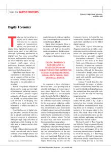
data. This reconstruction technique is based on sparse approximation of the phase and amplitude [4]-[6]. The developed algorithm is applicable to various phase-shifting scenarios. In this paper we demonstrate it for the standard four-step phase-shift setup. 2. OPTICAL SETUP AND SETTING OF THE PROBLEM We consider the two-beam interferometer and coordinates systems shown in Fig.1. A coherent laser beam of the wavelength λ is divided by beam splitter (BS) into two paths, one of which contains a transmitting or reflecting object and the other, a phase shifter. A thin lens focusses the object on the sensor plane, i.e., 1/z1 + 1/z2 = 1/f , where z1 , z2 are distances between object and lens, and between lens and sensor (e.g. a CCD camera), respectively; f is a focal distance of the lens. The magnification in this system is defined as M = −z2 /z1 . Assuming that the lens has large aperture size, it can be shown based on the wave field propagation theory [7] that ˜i (u, v) U
'
Uo,M (u, v)
=
Uo,M (u, v)K(u, v), u v 1 Uo ( , ) , M M M
(1)
Holography is a scheme for recording a wavefront of an object wave field and reconstructing a three-dimensional (3D) image of the object. The 3D object is modelled by a complex amplitude distribution. The phase defines a 3D shape of the object while the amplitude defines the intensity (brightness) of the reflected or transmitted light [1]. In digital holography, off-axis configuration and in-line phase-shifting interferometry are developed in order to obtain an object wavefront without superimposition of unwanted images, the zero-order diffraction wave or conjugate image [2]. However, the phase-shifting requires multiple exposures and is quite difficult to apply to dynamically changing scenes. Parallel phase-shifting digital holography has been proposed to achieve instantaneous measurement of a wide 3D area without unwanted images. In this technique, multiple phase-shifted holograms are recorded with a single-shot exposure of an image sensor by utilizing space-division multiplexing (e.g.[3]). The contribution of this paper concerns development of recursive non-linear algorithm which enables optimal object wavefront reconstruction from noisy
where Uo (x, y) is a complex object wavefront at the object plane, ˜i (u, v) is its projection on the sensor plane, and K(u, v) = U exp(j(z2 + z1 )k) × exp(j( 2zk2 (u2 + v 2 )), k = 2π/λ, is a phasor independent on object characteristics. ˜i (u, v) at the senor Within the factor K(u, v), the image U plane is a scaled copy of the object Uo (x, y), which is on the distance z1 + z2 from the sensor. Thus, if we reconstruct Uo,M (u, v) we obtain a scaled version of the object Uo (x, y). The total wavefront at the sensor plane is the sum of object ˜i (u, v) + U ˜r (u, v). Assuming that and reference wavefronts U the optical path is identical for both object and reference wave˜r (u, v) can be represented in the fronts, the reference wavefront U ˜r (u, v) = K 0 (u, v)Ur,M (u, v), where form similar to Eq.(1): U u v 1 Ur,M (u, v) = Ur ( M ,M )M is a scaled version the reference beam at the phase-shifting mirror, and K 0 (u, v) = K(u, v).Then, the intensity of the wavefront registered by the sensor is calculated as
∗ This work is supported by the Academy of Finland, project no. 138207, 2011-2014, by Portuguese Science and Technology Foundation under Projects PEst-OE/EEI/LA0008/2013 and PTDC/EEIPRO/1470/2012, and by Russian Ministry of Education and Science project within the state mission for institutions of higher education, Agreement No 2014/190.
˜i (u, v) + U ˜r (u, v)|2 = |Uo.M (u, v) + Ur,M (u, v)|2 . I(u, v) = |U (2) In this expression the phasor K(u, v) disappears and does not influence the observation I(u, v). Introducing the amplitude and the phase for the wavefronts, Uo,M = Bo exp(jϕo ), Ur,M =
c 978-1-4799-4758-4/14/$31.00 2014 IEEE
which can be interpreted as an exposure time and/or as a sensitivity of the sensor. We recall that the mean and the variance of Poissonian Ys are equal and given by Is χ, i.e., E{Y p s } = var{Y √s } = Is χ. The signal-to-noise ratio is E{Ys }/ var{Ys } = Is χ. Thus, smaller χ means a larger noise level and χ → ∞ corresponds to the noiseless case, Ys /χ → Is with the probability 1. 3. SPARSE MODELING OF PHASE AND AMPLITUDE
Figure 1. Arrangement for the phase-shifting holography with a thin lens between the object and sensor planes, Fig.(a): L, lens; BS, beam splitter; M, mirror; S, sensor. Fig.(b): The axes and distances between lens, object and sensor.
Ar exp(−jϕr ), we arrive to the equation Is = |Bo exp(jϕo ) + Ar exp(−jϕrs )|2 = Bo2
+
A2r
(3)
+ 2Bo Ar cos(ϕo + ϕrs ),
which are conventional in the phase-shifting interferometry. If the reference wavefront Ar exp(−jϕr ) is given and the phase ϕrs takes the values [0, π/2, π, 3π/2], then we may obtain estimates of the phase and the amplitude of the object Bo exp(jϕo ) are as follows [1]: v u 4 uX Y4 − Y2 ˜ , Bo = t Ys /4 − A2r , (4) tan(ϕ ˜o ) = Y1 − Y3 s=1 where Ys are noisy observations of Is . The reconstruction of the object (wavefront) phase ϕo and of the amplitude Bo from the noisy observations {Ys , s = 1, ..., 4} is the main topic of this paper. The solutions obtained according to Eq.(4) are usually quite noisy. Accordingly, we will use the term ˜o ). The straightforward idea to filter (ϕ raw data for these (ϕ ˜o , B ˜o , ˜o ) in order to reconstruct (ϕo , Bo ) is not productive because B ˜o ) is not additive, and, what is the noise in the estimates (ϕ ˜o , B even worse, it depends on unknown Uo,M . The iterative sparse phase and amplitude reconstruction (SPAR) algorithm, developed for fringe denoising in [4]-[6], is applied in this paper. It is based on the precise modelling of the noisy image formation and allows to get good results even for very noisy data. Comparison of these results versus those obtained by the straightforward filtering of ˜o ) is always in favor of the SPAR algorithm. (ϕ ˜o , B For simplicity in Eqs.(3)-(4) and in what follows, the arguments u, v are omitted. However, all calculations are pixel-wise with u, v defined on a rectangular regular grid. The measurement process in optics amounts to count the photons hitting the sensor’s elements and is well modeled by independent Poisson random variables. The observed random value Ys of the intensity Is has the following distribution: p(Ys = k) = k
exp(−Is χ) (Isk!χ) , where k is an integer number of photons, Is is the true intensity, and p(Ys = k) stands for the probability that Ys = k. Here χ is a scaling parameter of the Poissonian flow
In this paper, we use sparse modeling for processing phaseshifting interferometry measurements. Many images (and signals) admit sparse representations in the sense that they are well approximated by linear combinations of a small number of functions taken from a know set. Fundamentally, this is a consequence of the self-similarity of these image : it is very likely to find in them many similar patches in different locations and at different scales [8]. Let c ∈ Rn denote a vector representing an image, or a patch of it, and let us assume that admits a sparse representation or sparse coding with respect to the columns of a given matrix Ψ ∈ Rn×m ; i.e., it is possible to write c = Ψθ, where θ is a vector containing only a few non-zero components. The matrix Ψ is termedPa synthesis operator (or dictionary) because in the writing c = m j=1 Ψj ·θj , where Ψj are the columns of the matrix Ψ, and θj are the elements of the vector θ, c is synthesized as a linear combination of the columns of Ψ weighted by the elements of θ, often called the spectrum of c. The synthesis based representations have a dual point of view in which, given an image a ∈ Rm , we compute its spectrum β by applying the so-called analysis operator (or dictionary) Φ to a, i.e. β = Φa. It happens, that the synthesis dictionaries yielding sparse representations are often overcomplete, i.e., m > n. The concept of frame is a generalization of the classical basis especially developed for overcomplete (synthesis and analysis) representations with linearly dependent approximating functions [8]. Let Uo,M ∈ Cn be a complex valued wavefront defined on a grid with n pixels. Then Bo = mod (Uo,M ) and ϕo =angle(Uo,M ) are respectively, the corresponding images of amplitude (modulus) and phase. Herein, all functions applied to vectors are to be understood in the component-wise sense; the same applies to multiplications and divisions of vectors. With the objective of formulating treatable phase imaging inverse problems, most approaches follow a two-step procedure: in the first step, an estimate of the so-called principal (interferometric) phase in the interval [−π, π) is obtained. The latter procedure is known as phase unwrapping and corresponds to the addition of an integer number of 2π multiples to the estimated interferometric phase. Henceforth, we denote the principal phase as ϕo and the absolute phase as ϕo,abs We introduce the phase-wrap operator W linking the absolute and principal phase as ϕo =W(ϕo,abs ); the inverse of this operator denotes the unwrapping, ϕo,abs = W −1 (ϕo ). It is obvious that for the complex exponent there is no difference between the principal and absolute phase, exp(jϕo,abs ) = exp(jϕo ), and the angle operator in ϕo =angle(Uo.M ) gives the principal phase. Following [4], we introduce the sparse wavefront modeling by the formulas: mod(Uo,M ) = Ψa,o θa,o , ϕo,abs = Ψϕ,o θϕ,o ,
(5)
θa,o = Φa,o mod(Uo,M ), θϕ,o = Φϕ,o ϕo,abs ,
(6)
where θa,o and θϕ,o are, respectively, the amplitude and phase (absolute phase) spectra of the object Uo.M . In Eqs.(5), the amplitude
(mod(Uo,M )) and phase (angle (Uo,M )) are synthesized from the amplitude and phase spectra θa,o and θϕ,o . On the other hand, the analysis Eqs. (6) give the spectra for amplitude and phase for the wavefront Uo,M . The lo -norm of θa,o and θa,ϕ , denoted as ||θa,o ||0 and ||θϕ,o ||0 , counts the number of non-zero elements of these spectra and use as the measure of the sparsity of approximation for the amplitude and the phase, respectively. The approach proposed in this paper takes into full consideration the Poissonian (photon counting) measurements. In this way we are targeting at optimal sparse reconstruction both phase and amplitude of the object taking into consideration all details of the observation formation. 4. SPAR ALGORITHM
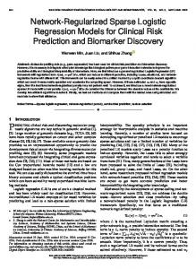
Figure 2. SPAR algorithm: block-scheme.
We consider the problem of wavefront reconstruction as estimation of Bo exp(jϕo ) from observations Ys , assuming that Ar and ϕrs are given. This problem is a rather challenging mainly due the periodic nature of the likelihood function with respect to phase ϕo . Herein, we adopt a multiobjective optimization [4], [9] approach to find an object. The main intention of the approach is simultaneous minimization of the minus log-likelihood function of observations (maximum likelihood approach) and the l0 -norms of amplitude and phase spectra supporting the sparsity of the estimates of these variables. The algorithm is derived from three successive stages minimizing three criteria. The details of mathematical formulation of the problems and their solutions can be seen [5],[6]. Here we present the general ideas of the algorithm and of its implementation. Recall that Φ and Ψ with the corresponding indexes are the analysis and synthesis matrices (dictionaries), respectively. Naturally, the success of the sparse imaging depends on how reach and redundant are the dictionaries used for the analysis and synthesis. In our experiments for the analysis and synthesis operations, we use the BM3D frames, where BM3D is an abbreviation for Block-Matching and 3D filtering [9]. Let us recall basic ideas of this advanced technique. At the first stage phase and amplitude of the wavefront are partitioned into small overlapping square patches. For each patch a group of similar patches is collected which are stacked together and form a 3D array separately for amplitude and phase. This stage is called grouping. The entire 3D arrays are projected onto a 3D transform orthonormal basis. The obtained spectral coefficients are hard-thresholded and inverse 3D transform gives filtered patches, which are returned to the original positions of these patches in the phase and amplitude images, respectively. This stage is called collaborative filtering. The process is repeated for all pixels of the entire wavefront. The final estimates of the amplitude and the phase are given by calculating weighted means of the estimates obtained for common pixels of the overlapped filtered patches of the amplitude and the phase. This last stage is called aggregation. The details of BM3D as an advanced image filter can be seen in [10]. In our technique, as it is implemented in this paper, grouping, analysis/synthesis defined by the formulas (5)-(6) and the hardthresholding are combined in a single procedure, which we call BM3D. Then, the basic algorithm iterations can be presented in the following short form: ˆot+1 = BM 3Dampl (B ˆot ), B ϕ ˆt+1 o,abs
=
BM 3Dangle (ϕ ˆto,abs ),
(7) t = 0, 1, 2, ...,
where ϕ ˆo,abs is the absolute (unwrapped) phase corresponding to the wrapped phase ϕ ˆo . The sparse approximations of the absolute
phase and the amplitude are used in the algorithm. We use different indexes for BM3D applied to the amplitude and to the phase, because different parameters of BM3D can be used for amplitude and phase. Overall the algorithm is named Sparse Phase and Amplitude Reconstruction (SPAR) algorithm. The main stages of the developed algorithm are summarized in the block-scheme shown in Fig. 2. The iterative SPAR algorithm is initialized by an initial guess ˆo0 ). It is generated as follows. Profor the object wavefront, (ϕ ˆ0o , B vided given Ar the raw data for Bo and ϕo can be obtained from the observations Ys using the formulas (4). As it is mentioned earlier these estimates can be very noisy and should be filtered. In ˜ which give our experiments we use BM 3Dampl for filtering of B, 0 ˆ ˜ Bo = BM 3Dampl (Bo ), and for filtering of the wrapped phase ϕ ˜o we use the W F T (windowed Fourier transform) algorithm developed in [11], which gives for initialization of the interferometric phase ϕ ˆ0o = W F T (ϕ ˜o ). Both algorithms BM 3Dampl and W F T demonstrate the state-of-the-art results in the corresponding fields for the image and the wrapped phase denoising, respectively. In Fig.(2) vs is an auxiliary estimate of the total wavefront at the sensor plane us = Uo.M (u, v) + Urs ,M (u, v). The successive stages of the algorithm give: uts as a result of observation denoising, the parametrization of u ˆto gives the estimates for the phase ϕ ˆto t ˆo , BM3D is used for filtering of the amplitude B ˆot and amplitude B t t ˆo , finally the variand the absolute phase ϕ ˆo,abs obtained from ϕ able vst is updated. The output of the algorithm is defined by the ˆot ). sequence (ϕ ˆto , B 5. EXPERIMENTS The experiments presented in this section are obtained for the quadratic amplitude and the Gaussian phase surface. The ratio of the maximum-to-minimum values of the amplitude is equal to 2 with the maximum value at the central point of the aperture. It imitates the non-uniformity of the laser wavefront intensity. The accuracy of the wavefront reconstruction are characterized: by ISN R (improvement in signal-to-noise) criterion indeˆot and the exponential complex compendently for the amplitude B t ponents exp(j ϕ ˆo ), respectively by ISN Rampl and by ISN Rexp , and by RM SE criterion for the absolute phase. All results are shown for 50 iterations of the algorithm. Fig.3-Fig.4 show the reconstruction results for the Gaussian phase, of the range 44 radians, the scale parameter χ of the Poissonian distribution (level of the noise) is equal to 0.05. We can ˜o (Fig.5a) obtained acsee that the raw data ϕ ˜o (Fig.3a ) and B cording to Eq.(4) are indeed extremely noisy. Fig.3b and Fig.5b ˆo0 obtained by pre-filtering of these noisy data as show ϕ ˆ0o and B
INITIAL, ISNREXP=8.54 dB
NOISY DATA
SPAR, ISNREXP=15.9 dB
7. REFERENCES
TRUE
[1] Th. Kreis, Handbook of Holographic Interferometry. WileyVCH, Berlin, 2005. (a)
(b)
(c)
(d)
Figure 3. Interferometric phase for the Gaussian phase object, from left to right: the raw noisy data, the initial W F T estimate ϕ ˆ0o , SP AR reconstruction ϕ ˆ50 , true image. o
[2] I. Yamaguchi and T. Zhang, ”Phase-shifting digital holography,” Optics Letters, vol. 22, no. 16, pp.1268-1270, 1997. [3] M. Lin, K. Nitta, O. Matoba, and Y. Awatsuji, ”Parallel phase-shifting digital holography with adaptive function using phase-mode spatial light modulator,” Applied Optics, vol. 51, no. 14, pp. 2233-2237, 2012. [4] V. Katkovnik and J. Astola, “ High-accuracy wavefield reconstruction: decoupled inverse imaging with sparse modeling of phase and amplitude, ” J. Opt. Soc. Am. A 29 ,pp. 44 – 54, 2012. [5] V. Katkovnik, J. Bioucas-Dias, H. Hao, ””Wavefront reconstruction from noisy fringe observations via sparse coding,” Proceedings, Fringe 2013: 7th International Workshop on Advanced Optical Imaging and Metrology, pp. 179-184, 2013.
Figure 4. The absolute (unwrapped) phase for the Gaussian phase object, from left to right: the initial W F T estimate ϕ ˆ0o,abs , SP AR reconstruc50 ˆ tion protectϕ o,abs , true image.
[6] V. Katkovnik and J. Bioucas-Dias, ”Wavefront reconstruction in phase-shifting interferometry via sparse coding of magnitude and phase,” J. Opt. Soc. A, 2014 (in print). [7] J. Goodman, Introduction to Fourier Optics, Third ed. MaGraw-Hill, 2005. [8] M. Elad, Sparse and Redundant Representations: from Theory to Applications in Signal and Image Processing, Springer, 2010. [9] A. Danielyan, V. Katkovnik, and K. Egiazarian, “ BM3D frames and variational image deblurring, ” IEEE Trans. Image Process. 21 , pp. 1715 – 1728, 2012.
Figure 5. Surfaces for the quadratic amplitude of Gaussian phase object, ˆ0, from left to right: the noisy raw data, the initial BM3Dampl estimate B o SP AR reconstruction ϕ ˆ50 o , true image.
ˆo0 = BM 3Dampl (B ˜o ). The next Fig.3c ϕ ˆ0o = W F T (ϕ ˜o ) and B and Fig.5c demonstrate the performance of SP AR; the obtained SP AR results are very close the true values of the wrapped phase and the amplitude, shown in Fig. 3d and Fig. 5d. In Fig.4 we present the corresponding results for the unwrapped phase, respectively: ϕ ˆ0o,abs (Fig. 4a), ϕ ˆ50 o,abs (Fig.4b) and the true absolute phase (Fig. 4c). 6. CONCLUSION Digital phase-shifting holography is considered. A thin lens between object and sensor planes results in that a scaled copy of the object wavefront is appeared at the sensor plane. The variational maximum likelihood technique is developed for phase and amplitude reconstruction of the coherent wavefront from Poissonian intensity measurements. Sparse modeling of amplitude and absolute phase of the wavefront is one of the key elements of the developed algorithm. The experiments show that the new algorithm yields the state-of-the-art accuracy for reconstruction both phase and amplitude of the object wavefront.
[10] K. Dabov, A. Foi, V. Katkovnik, and K. Egiazarian, “Image denoising by sparse 3D transform-domain collaborative filtering”, IEEE Trans. Image Process., vol. 16, no. 8, pp. 2080-2095, 2007. [11] Q. Kemao, ”Windowed Fringe Pattern Analysis,” SPIE, Bellingham, Whashington, 2013.