Digital Transmission Range Sensor (DTR) Update ... Once the wiring
connections are complete, please take note of the two new settings that have
been added ...
Baumann Engineering
702 S. MECHANIC ST . PENDLETON, SOUTH CAROLINA . 29670 . (864) 646-8920 FAX (864) 646-8925
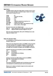
Digital Transmission Range Sensor (DTR) Update (for the Baumannator TCS and Ford RWD Transmission Applications) Beginning with the 1997 Expedition, Ford Motor Co. has been using a “digital” transmission range sensor to indicate gearshift position in both AOD-E/4R70W and E4OD/4R100E transmission applications. 1997 and 1998 model year DTR sensor coverage varies, with all 1999 rear-wheel-drive models using DTR sensors in lieu of the older analog “TRS” or “MLPS” sensor. The new sensor may be identified by the use of a twelve-position connector at the sensor, instead of the eight-position connector used with the previous unit (please note that all eight or twelve connector pin positions will not necessarily be utilized). The new sensor requires three additional wiring connections between the TCS and the range sensor. This is because the PCM checks the state of four binary (on-off) inputs, instead of one analog input with six distinct valid voltage levels to indicate the selected transmission range (e.g. P, R, N, etc.). The digital range sensor contains error checking and is much less susceptible to errors caused by moisture intrusion and sensor wear. Another mode that has been added to the Baumannator TCS is the ability to share the range sensor inputs with an OEM PCM in addition to operating in a complete stand-alone mode. This is accomplished by using an alternate input (TCS pin 6, versus pin 5) for the analog range sensor signal. The analog range sensor input is used for the single input from an analog range sensor as well as the TR3A input from digital range sensors. The TR3A terminal of the digital range sensor contains a fault-detection resistor, which mandates an analog input for that signal. The other three inputs from digital range sensors (TR1, TR2 and TR4) are true digital inputs and do not require any special consideration. The alternate analog input (Pin 6) may be used for digital or analog range sensors, allowing either type to be used in conjunction with a stock PCM. Pin 6 allows sharing the analog range sensor or TR3A signal with a stock PCM by limiting the “pull-up” current sent to the range sensor. Since the OEM PCM already contains an internal pull-up resistor for the analog range sensor input, it is necessary to use Pin 6 for the analog input if the OEM PCM is also connected to this signal. If this is not done, the excessive pull-up current will cause the range sensor voltage to be read incorrectly (voltage too high) by both the PCM and the Baumannator TCS. This will cause an incorrect range indication with analog sensors or will cause a digital range sensor to be seen as defective by the TCS and PCM (causing the TCS to default to “Drive” range). The connection diagram below illustrates the proper connection of a digital transmission range sensor to the Baumannator TCS. As detailed above, please attach the TR3A analog input signal (wire color LB/Y) to TCS pin 5 or 6, as appropriate. Please note that the analog input (pin 5 or 6) selection and LB/Y wire color applies to older analog type range sensors as well. Other than the three additional connections shown (TCS pins 10, 21 and 22), all other TCS and vehicle connections remain identical to the analog TRS connections shown in the Baumannator TCS instruction manual. In addition, the Neutral Safety Switch and Backup Light Switch connections to the digital range sensor are identical to those shown for the analog range sensor in the installation manual.
Baumannator TCS (Pin Numbers
17
Main Gnd
To all main ground connections per installation manual diagram
Black
Shown at Gy/R
Right.) 5 or 6 * TR3A / Analog TRS 10 TR1
LB/Y - Ford ckt# 199 Y/Bk - Ford ckt# 1144
22
TR2
LB/Bk - Ford ckt# 1145
21
TR4
W/Bk - Ford ckt# 1143
* Connect to Pin 5 or 6, as per text.
Digital Range Sensor
To Ford PCM, if needed (see text)
Once the wiring connections are complete, please take note of the two new settings that have been added to the Vehicle Setup menu in the TCS software application. At the bottom of the vehicle setup menu, you will notice a group of settings labeled “DTR Options” containing two check boxes. As you may expect, the “Use DTR” checkbox will allow the TCS to be used with a digital range sensor when checked and should be un-checked if you are using the older analog type range sensor. The “Share with PCM” checkbox allows an analog or digital range sensor to be connected to both the TCS and a Ford PCM when checked. This checkbox must be set in conjunction with selecting the correct analog input, as mentioned above. In other words, if you are using Pin 5 for the analog or TR3A input, the “Share with PCM” checkbox should not be checked. If you are using Pin 6 for the analog range sensor or TR3A input, the “Share with PCM” checkbox should be checked. As always, you must set these check boxes appropriately in both of your calibrations and write both calibrations to the TCS to activate these settings. Please note that these settings will not have any effect on earlier Baumannator TCS units. If you have an earlier TCS unit and would like to have it upgraded to support these features you may contact us for a low cost upgrade. If you have any questions about these procedures, you may contact us via telephone or through Email via
[email protected].
© 1999, Baumann Engineering and Design