International Archives of the Photogrammetry, Remote Sensing and Spatial Information Sciences, Volume XL-1/W2, 2013 UAV-g2013, 4 – 6 September 2013, Rostock, Germany
DIRECT PHOTOGRAMMETRY USING UAV: TESTS AND FIRST RESULTS F. Chiabrando,a A. Lingua,b M. Pirasb a
b
Politecnico di Torino, DAD, 10129, Torino, Italy,
[email protected] Politecnico di Torino, DIATI, 10129, Torino, Italy, (andrea.lingua, marco.piras)@polito.it Commission I, ICWG I/5
KEY WORDS: Direct photogrammetry, GNSS/INS, MEMS, DTM/DSM, UAV
ABSTRACT In recent years, the quality of high resolution acquisition platforms for geomatic applications has decidedly increased, especially in the performance of the sensors devoted to image acquisition. The small size of these new sensors combined with the increase in resolution allows them to be easily mounted onto Unmanned Aerial Vehicles (UAVs); in particular, calibrated, very-high-resolution digital cameras for photogrammetric purposes such as digital terrain model (DTM) and digital surface model (DSM) extraction, orthophotos, and map realization have been used. In this case, the UAV performance allows a high quality product to be obtained, considering the pixel size and the accuracy of the DTM/DSM which could be obtained with automatic procedures. Several navigation sensors (GPS/GNSS and IMU-MEMS) are embedded into UAVs in order to realize autonomous flight. The quality of these sensors, in terms of accuracy, depends on the model of UAV and its purpose. The navigation solution (position and attitude) is estimated by the internal UAV sensor and can be employed to directly georeference the images, in order to produce an quick and easy description and analysis of the overlooked area. This is a good condition for semi-automatic procedures using a bundle-block photogrammetric approach. But is it possible to realize a direct photogrammetry? And what are the limits? Several tests were carried out over different areas and in different conditions using three different UAVs belonging to the Geomatics group of the Politecnico di Torino. In this paper, an investigation of the limits of some commercial UAVs is reported, defining a dedicated procedure to valuate their performance, especially considering the use of UAVs for direct photogrammetry.
of the DTM/DSM which could be obtained with automatic procedures.
1. INTRODUCTION The small dimension of these new sensors combined with the increase in resolution makes it possible to easily mount them onto Unmanned Aerial Vehicles (UAVs) for several types of applications: documentation, photography, and aerial videos are some possible purposes. Nowadays, the number of activities in which dedicated data acquisitions over small areas are requested is increasing; they include for example cadastre applications, map upgrading, safety, and security. The use of UAV systems for these applications can be easily realized and has been described in several scientific papers (Barazzetti et al., 2012; Chiabrando et al., 2012; Haala et al., 2011; Lingua et al. 2008; Remondino et al., 2011). UAVs are increasingly used with onboard calibrated very-high-resolution digital cameras for photogrammetric purposes such us DTM and DSM extraction and realization of orthophotos and maps, combining the digital images with a sufficient number of ground control points using semiautomatic image-matching techniques combined with a traditional bundle-block approach.
Moreover, as the new algorithms employed in photogrammetry for the image-matching approach require a high percentage of overlap (> 85% is a good value), only a few ground control points (GCPs) are needed to orient a complete photogrammetric block. This is a good condition for semi-automatic procedures using a bundle-block photogrammetric approach. But is it possible to realize direct photogrammetry? And what are the limits? A large number of navigation sensors are available off the shelf (GPS/GNSS and Inertial Measurement Unit (IMU) - Micro Electro-Mechanical Systems (MEMS)), and they can be immediately embedded into a UAV in order to realize an autonomous flight. The quality of these sensors, in term of accuracy, depends on the model of UAV and its purpose. The navigation solution (position and attitude) is estimated by the internal UAV sensor and can be employed to directly georeference the images, in order to produce a quick and easy description and analysis of the area (Blaha et al., 2011; Coppa et al., 2009).
In this case, the UAV performance makes it possible to obtain a high quality product, considering the pixel size and the accuracy
This contribution has been peer-reviewed.
81
International Archives of the Photogrammetry, Remote Sensing and Spatial Information Sciences, Volume XL-1/W2, 2013 UAV-g2013, 4 – 6 September 2013, Rostock, Germany
The sensors usually installed on a UAV do not have special performance requirements for photogrammetric applications (e.g. GPS dual frequency or “strategic class” IMU”), and thus it is interesting to analyse their performance for estimating the accuracy and precision of the positioning and attitude of both the vehicle and the camera used.
aeroplane (Bendea et al., 2007). UAVs are mainly used for photogrammetric applications, in particular to realize maps or DTMs in a rapid way. Currently, the Geomatics group has three different UAVs: 1)
In this paper, the authors present a research on the performance of mini-UAVs, considering in particular some commercial UAVs, defining a dedicated procedure to valuate their performance, especially for direct photogrammetry. Several tests were carried out over different areas and in different conditions using three different UAVs belonging to the Geomatics Group of the Politecnico di Torino. In two tests, the data were elaborated with photogrammetric bundle-block adjustment (BBA) in order to estimate the correct camera position and attitude, and after that the autonomous solution estimated by the UAV was compared with the estimated one.
2)
3)
2.1
a hexacopter produced by Microkopter (2011) (hereafter HEX1); a hexacopter produced by Microkopter and modified by the Italian company RESTART (2012) (hereafter HEX2); a DRAKO system produced by SELEX GALILEO (hereafter DRA).
Microkopter hexacopter version 1
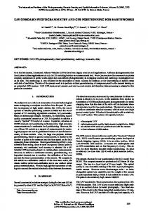
This system is a commercial solution available off the shelf and is a cheaper tool than the traditional UAV (Figure 1, left). Its cost is less than 5000€, considering the commercial kit and assembly step.
In a second test a first attempt at the realization of an automatic orthophoto was carried out. In another case, a traditional surveying method was employed in order to verify the accuracy of the estimated trajectory by the internal navigation sensors of the UAV; in particular an automated motorized total station (TPS) was employed. A special retro-reflector was realized and installed on the bottom of the UAV to track the system continuously during the flight with the aim of comparing the two available solutions: UAV and TPS. The analysis was conducted considering the synchronism with the measurements and tracking of the UAV for a long time, obtaining a large number of points to be compared. The first results encourage the use of UAVs for geomatic applications, because the cost and quality of the obtained products are quite interesting. The quality of positioning and attitude of the tested UAVs in terms of accuracy and precision makes it possible to realize a direct photogrammetry approach, but only to produce maps at medium scale (1:10000–1:25000). The most critical aspect is the accuracy of position (X, Y, Z), but it can be solved by adopting an additional dual frequency GNSS receiver dedicated exclusively to this purpose, without changing the internal navigation board, making it possible to work with the current system, or using a navigation control board with a high performance (and consequent high cost), but in this case it could be necessary to define new procedures (hardware and software) devoted to realizing the autonomous navigation.
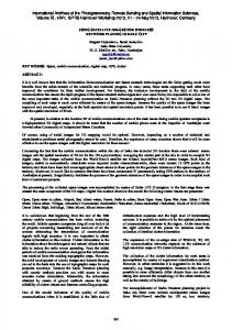
Figure 1 First version of Microkopter hexacopter (left); on board camera (right). This standard hexacopter allows an autonomous flight, thanks to the navigation control and flight control cards shown in Figure 2. In this case a GPS u-blox 6H has been embedded. The main performance of this GPS module are reported in Table 1 (Piras et al., 2010). Number of Channels Type of constellation Time to first Fix Horiz. Acc. [m] Heading Acc. [°] Velocity Acc [m/s] Sensitivity
Table 1 Main performance of the GPS module u-blox 6H The performances of the internal IMU are not declared because this sensors is embedded in the NAVI-control card. After some test in the lab, hypothetic performances of this sensor have been defined as shown in Table 2.
Moreover, the quality of sensors is increasing every day, and thus it is desirable for a new generation of navigation sensors to be available in the future. In this paper the main characteristics of the UAVs used during the tests, the analysis carried out, and the first results are reported. Finally the limits and possible improvements for direct photogrammetry applications will be highlighted. 2. DESCRIPTION OF THE UAVS USED Since 2006, the Geomatics Group of the Politecnico di Torino has been working on a UAV system using a small fixed-wing
50 GPS (L1), SBAS, GLONASS, GALILEO (Open Service) 26s (cold start) - 1s (hot start) 2.5 (without aiding) – 2 (w SBAS) 0.5 0.1 -162 dBm
St. Dev. Yaw St. Dev. Pitch St. Dev. Roll Horiz. Accur. Vert. Accur.
± 6° ± 3° ± 3° 3m 6m
Table 2 Estimated performance of the embedded IMU GPS and IMU can be setting in order to have a dynamic model, with respect the vehicle where they are installed. This aspect is
This contribution has been peer-reviewed.
82
International Archives of the Photogrammetry, Remote Sensing and Spatial Information Sciences, Volume XL-1/W2, 2013 UAV-g2013, 4 – 6 September 2013, Rostock, Germany
important because allows to define the transition matrix in the Kalman filter, which permits that the navigation solution, provided as PVT (positioning, velocity, and timing), to be estimated in real time, and moreover, using the internal inertial sensors, it is possible to immediately obtain an integrated solution using a loosely coupled algorithm. This aspect is particularly interesting because all of the fundamental information used for direct photogrammetry (position and attitude) is available at each epoch. Unfortunately, at the moment it is not possible to acquire the raw data, which would be interesting in order to improve the quality of the navigation solution. The quality of the positioning has a metrical level of accuracy, but is it enough for our goal? It will be investigated in the following part of this paper. A flight control is coupled with the NAVI-control, with the purpose of managing each brushless control, where each rotor engine is connected.
Figure 3 The Microkopter hexacopter modified by RESTART
In this case, a special retroreflector prism has been installed on the bottom of the UAV, along the barycentre line of the system. This special prism has been realized in the labs of the Geomatic group at the Politecnico di Torino by assembling four single small prisms traditionally used for surveying. The aim of this support is for the UAV to be tracked by an automatic total station (ATS) in real time, in order to estimate the three-dimensional position of the UAV with a centimetric level of accuracy. The duration of the flight is 14–16 minutes, which is longer than the previous one. 2.3
Figure 2 NAVI-control and flight control It is also possible to set a flight plan composed of several waypoints, where it is possible to indicate the compass angle during the flight and the time of waiting over each point. This aspect is very important for geomatic applications because it allows the flight to be realized over an area or points of interest by fixing the compass of the UAV. These operations can be available by means of a complex communication system between the UAV, the pilot, and the ground control stations There is, in fact, continuous communication between the UAV and the ground control station in order to transmit the telemetry and other information to the pilot. The duration of the flight depends on the payload: on average it is possible to fly for 8–10 minutes with a payload of up to 900 g, which completely satisfies the requirements of a photogrammetric application (digital camera). 2.2 Microkopter RESTART
hexicopter
version
2
modified
by
In 2012, a new version of the hexacopter was bought with the purpose of increasing the payload (up to 1.2 kg) (Figure 3).
DRACO–SELEX GALILEO
This system is a quadricopter and it is a unique UAV belonging to the Politenico di Torino which is not a commercial solution but comes directly from military experience. This system (Figure 4) is a prototypal solution for civilian applications which has been developed by SELEX. The UAV component, the ground control station and the flight are completely different from the previous ones. In this case the entire UAV is realized with carbon fibre, and the NAVI control and the flight control card are housed under a special cap and are covered by a special patent. It is only declared that the GPS used is a u-blox 6H, which has the performances illustrated in Table 1. The DRACO is piloted with a special controller, which is directly connected with the ground control station. This controller has a small LCD where it is possible to see the map in real time or the video which is streamed by the UAV. Using the controller, the pilot can also create a mission, set the flight plan, set the shooting time, and so on. The duration of the flight is better: 16–18 minutes.
The commercial kit is similar to the previous one, but the system has been modified by an Italian company called RESTART which has expertise in UAV assembly. In particular, the engines and propellers have been changed and the NAVI control and flight control have been also modified. In this case, a GPS u-blox 6H has been installed. The performances of internal GPS and IMU are the same reported in Table 1 and Table 2.
Figure 4 DRACO system
Like the previous hexacopter, it is possible to have an autonomous flight, and a flight plan can be realized.
This contribution has been peer-reviewed.
83
International Archives of the Photogrammetry, Remote Sensing and Spatial Information Sciences, Volume XL-1/W2, 2013 UAV-g2013, 4 – 6 September 2013, Rostock, Germany
flight (17 m); for the two flights a previously acquired LiDAR survey was employed as a digital elevation model (DEM).
3. CASE STUDIES AND RESULTS Each UAV has different characteristics (e.g. internal sensors, duration of flight), and each system has been tested at a different test site in Italy. In the following sections, the different tests carried out will be described and moreover the measurement techniques and type of survey will be analysed.
The required accuracy for the aforementioned product was checked on some CPs and the discrepancy for both flights is under 2 cm (the typical accuracy required for a map at a scale of 1:100).
For each test, the results obtained will be reported and discussed, with the purpose of investigating the extent of the possibilities for using these UAVs for direct photogrammetry and their main weaknesses. Before discussing the results and the quality of the navigation solution for direct photogrammetry, it is important to remark that each map has a different accuracy which depends on the scale factor. The accuracy is: XYZ = 0.2 n
(1) Figure 9 High flight block (left), low flight block (right)
where: XYZ = map accuracy; n = scale factor. 3.1
Average Flight Height [m] 17
Aquileia (UD), Italy: test with HEX1
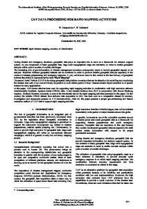
The HEX1 system was employed in the archaeological area of Via Gemina in Aquileia (UD), Italy. In order to analyse the different achievable results, two different flights were realized according to the shape of the area. The first one, over the area of the Domus of Putti Danzanti, was carried out at an average flight height of 17 m in order to realize a complete orthophoto of the Domus. The second one, which was planned at an average flight height of 14 m, covered a portion of a Roman street (Cardo) that was discovered during excavation work in the area of Via Gemina. The aim of this second flight, as for the first one, was to realize an orthophoto. In order to achieve these objectives, first of all several markers (Figure 8, yellow box) were well distributed in the test area, all the positioned points were measured using a traditional Total Station (TS), and finally the flights were performed. An example of captured image is shown in Figure 8 (left). For each flight, using the measured markers as GCPs or as Control Points (CPs), the typical photogrammetric BBA was performed. The following figure shows a screen shot of the two blocks. The results of the photogrammetric process are shown in Table 1, where the standard deviations on the GCPs and the CPs are reported (0 = 10).
14
E [m] N [m] H [m] GCPs (58) 0.004 0.005 0.012 CPs (20) 0.006 0.009 0.012 GCPs (30) 0.003 0.002 0.011 CPs (15) 0.010 0.005 0.020
Table 3 Standard deviations on the GCPs and the CPs in the analysed flights Finally, in order to pursue the main aim of the research a comparison between the information derived from the onboard sensors (GPS and IMU) and the results obtained after the BBA concerning the coordinates (E,N,H) and the attitude (,,) of the centre of the poses was calculated. The results concerning the high flight are reported in Table 4 (around the same discrepancy has been achieved in the low flight). E [m] N [m] H [m] [gon] [gon] [gon] 0.321 0.575 Mean 1.377 0.556 –0.338 0.687 1.781 2.103 4.223 1.888 1.601 4.254 St D –0.078 –2.817 –6.252 –4.827 –3.155 –10.37 Min 3.188 5.211 7.168 5.697 5.091 12.30 Max Table 4 Summary of the results for the first data set (high flight). These results underline that is possible to realize direct photogrammetry with this UAV, but not at the same scale as that used for the test area.
Figure 8 Two acquired images in the area of Via Gemina: high flight (left) and low flight with a zoom on a target (right). According to the BBA results, the orthophotos were realized at a scale of 1:100 for the low flight (14 m) and 1:200 for the high
The table shows that the attitude discrepancy is lower than the horizontal and vertical ones and in theory these results allow a map with a scale of 1:1000 to 1:2000 to be realized. On the other hand the results of the comparisons of the horizontal and vertical components are suitable for the realization of a map with a scale close to 1:25000 (especially due to the vertical part).
This contribution has been peer-reviewed.
84
International Archives of the Photogrammetry, Remote Sensing and Spatial Information Sciences, Volume XL-1/W2, 2013 UAV-g2013, 4 – 6 September 2013, Rostock, Germany
As a conclusion of this first test it is possible to state that using only the information derived by the on-board HEX1 sensors (used for direct photogrammetry), it is not possible to realize suitable maps for cultural heritage documentation (very large scale) since the achievable accuracy is closer to the requirements of medium scale maps (1:10000–1:25000). 3.1
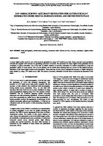
Figure 11 (left) shows the achieved depth maps of the Leri Cavour area and Figure 11 (right) shows the orthophoto realized. The processing steps were carried out using 54 images acquired at an average flight height of about 40 m.
Leri Cavour (VC), Italy: Test with HEX1
According to the achieved results of the aforementioned test a different approach was followed at the second test site: Leri Cavour (AL). Leri Cavour (Figure 10) is an abandoned farmstead complex that is under a regional requalification project.
In order to evaluate the accuracy of the obtained orthophoto, several CPs were compared with the coordinates obtained from the traditional topographic survey. The discrepancy between the two coordinate set for all of the CPs was close to 60 cm, with some “outliers” close to 2 m along the borders of the orthophoto.
Figure 11 Depth maps obtained with MicMac (shaded mode) (left) and achieved orthophoto (right) Figure 10 Aerial view of Leri Cavour (left) and two images of the actual state of the main buildings (right). The aim of the UAV survey was again the realization of an orthophoto at a very large scale, but in this case the objective was to follow a more automatic procedure for the BBA, generation of the DEM, and the production of the final orthophoto.
3.2
Medicina (BO), Italy: test with HEX2
The HEX2 system was tested in Medicina (BO) over a test site dedicated to astronomical surveys. In this case, several flights were realized with the same ground height of around 60 m. The UAV trajectory was tracked continuously with three different automated TSs, with a sample rate equal to 5 Hz.
In order to achieve these results the open source software MicMac realized by IGN France was employed.
E [m] N [m] H [m]
According to the traditional steps of photogrammetric data processing, first of all automated tie point extraction is carried out, and after that the bundle adjustment and the camera parameters are computed. Moreover dense image matching for surface reconstruction is realized and finally the orthoimages are generated (Pierrot-Deseillign and Paparoditis, 2006; PierrotDeseillign and Clery, 2011). The strategy followed for the area of Leri Cavour was based on the phases below: – Tie point extraction; – BBA using the pose coordinates derived from the onboard GPS (in order to perform the BBA it is possible to input the approximate coordinates of the poses in MicMac); – DSM generation; – Orthophoto generation. Finally a check on the achieved accuracy of the orthophoto was performed on several points previously measured using a Total Station.
–0.034
0.890
0.277
St. Dev. 2.420
1.744
1.465
Mean
The software was developed by the MATIS laboratory and was delivered as open source in 2007. It is usable in different contexts (satellite, aerial, terrestrial) for extracting point clouds from images.
Min
–9.841 –6.977 –8.794
Max
7.906
11.402
9.352
Table 1 Summary of horizontal and vertical differences At the end of the tests, more than 20000 points were collected, both with internal GPS of the UAV and with TSs. Each pair of trajectories was compared, calculating the horizontal and vertical differences. In this case, the accuracy of the position (in all components) allows a map with a scale factor equal to 1:10000 to be realized. 3.3
Rivoli (To), Italy: Test with DRA
The DRA system has been tested in Rivoli (TO) over an airfield. As for the case of the HEX1 test, a special calibration field was realized in order to realize an aerial triangulation, and 450
This contribution has been peer-reviewed.
85
International Archives of the Photogrammetry, Remote Sensing and Spatial Information Sciences, Volume XL-1/W2, 2013 UAV-g2013, 4 – 6 September 2013, Rostock, Germany
images were collected with an average ground height of 18 m, but only 51 were used for this test. The difference between the estimated and measured coordinates is reported in Table 4. E [m] mean 0.318 St.Dev. 0.858 Min –1.099 Max 2.266
N [m] 1.126 1.005 –1.577 3.456
H [m] [gon] [gon] [gon] –0.870 0.665 –0.034 –0.085 0.971 1.791 1.712 3.501 –2.817 –4.058 –7.658 –9.214 –1.697 6.272 6.139 –10.321
Table 2 Summary of horizontal and vertical differences These results demonstrate that it is possible to realize direct photogrammetry with this UAV, but with different scale factors. The effects due to only the altitude allow a map with a large scale such as 1:1000 or 1:2000 to be realized.
Blaha, M., Eisenbeiss, H., Grimm, D., Limpach, P., 2011. Direct georeferencing of UAVs. Proceedings of the International Conference on Unmanned Aerial Vehicle in Geomatics (UAV-g), Zurich, Switzerland, Vol. XXXVIII1/C22. Chiabrando, F., Lingua, A., Rinaudo, F., Spano, A., 2012. Archaeological site monitoring: UAV photogrammetry can be an answer. ISPRS Archives, Vol. XXXIX, no. B5, pp. 583–588. Coppa, U., Guarnieri, A., Pirotti, F., Vettore, A., 2009. Accuracy enhancement of unmanned helicopter positioning with low cost system. Applied Geomatics, 1(3), pp. 85–95. Haala, N., Cramer, M., Weimer, F., Trittler, M., 2011. Performance test on UAV-based photogrammetric data collection. In: ISPRS Archives, Vol. XXXVIII–1/C22.
It is possible to realize a map with a scale factor equal to 1:5000, considering the accuracy of the three-dimensional components (XYZ).
Lingua, A., Marenchino, D., Nex, F., 2009. Automatic Digital Surface Model (DSM) generation procedure from images acquired by Unmanned Aerial Systems. Proceedings of GeoCad 2009, Alba Iulia, Romania.
In this case, the quality of the internal navigational sensors (GPS and IMU) leads to a better performance than the previous one, allowing a map to be created with a medium scale factor, using only the internal solution.
Pierrot-Deseillign, M., Paparoditis, N., 2006. A multiresolution and optimization-based image matching approach: An application to surface reconstruction from SPOT5-HRS stereoimagery. In: IAPRS, Vol. XXXVI-1/W41
4. CONCLUSION The tests carried out allow us to state that, at present, the tested UAV systems do not allow us to perform direct applications of photogrammetry at very large scale. Actually the characteristics of the achieved results show that the data derived from the onboard sensors can be used for mapping applications to a medium scale. The main problem is not in the estimation of the angles but in the definition of the position of the centre of the camera (GNSS) due to the use of sensors and procedures in real-time which do not guarantee the precision and the required accuracies. As shown in the previous sections, the presence of the finest synchronization and the most expensive IMU parameters of exterior orientation of each image significantly improve the data; unfortunately these data are only available using the DRACO system, which at the moment has only been employed on the airfield area. Further tests are still in progress with all of the available UAVs; in particular the data concerning some flights acquired with a different on-board positioning system (dual frequency GNSS) are in the process of being checked and the first encouraging results are very interesting in terms of achieved accuracy. REFERENCES Barazzetti, L., Remondino, F., Scaioni, M., Brumana, R., 2012. Fully automatic UAV image-based sensor orientation, IAPRS&SIS, Beijing (China). Bendea, H., Chiabrando, F., Giulio Tonolo, F., Marenchino, D., 2007. Mapping of archaeological areas using a low-cost UAV. The Augusta Bagiennorum test site. XXI CIPA International Symposium, Athens, Greece, 1–6 October 2007.
Pierrot-Deseilligny, M., Clery, I., 2011. APERO, an open source bundle adjustment software for automatic calibration and orientation of a set of images. ISPRS Archives, International Workshop 3D-ARCH, Trento, Italy. On CD-ROM. Piras M., Marucco G., Charqane K., 2010. Statistical analysis of different low cost GPS receivers for indoor and outdoor positioning. In: 2010 IEEE/ION Position, Location And Navigation Symposium, Palm Springs (USA), May 4-6, 2010. pp. 838-849. Remondino, F., Barazzetti, L., Nex, F., Scaioni, M., Sarazzi, D., 2011. UAV photogrammetry for mapping and 3d modeling – current status and future perspectives. Proceedings of the International Conference on Unmanned Aerial Vehicle in Geomatics (UAV-g), Zurich, Switzerland, Vol. XXXVIII1/C22. ACKNOWLEDGEMENTS The authors would like to thank Leica Geosystems (dott. Rispoli) for the TS30 total station. We are grateful to Geotop (Engg. Birocco, Pasquini, Centanni) for allowing us to use the Topcon GPT 8201 for tracking the Hexacopter by TopSURV. We thank Prof. Federica Fontana (chief of the archaeological site of Aquileia) and all students of the Archaeological Summer School of the University of Trieste for their warm hospitality and rich collaboration. Special thanks are due to the IEIIT (Eng. Virone amd Olivieri) of the CNR and the INAF (dott. Monari and Perini) for their cooperation.
This contribution has been peer-reviewed.
86