them to pick the best one for their problem. ... product of a good conventional development approach. ... over 6000 notebook computers on an average day. Dell.
Disciplined Methods of Software Specification: A Case Study* Robert L. Baber, David L. Parnas, Sergiy A. Vilkomir Software Quality Research Laboratory (SQRL) Department of Computer Science and Information Systems, University of Limerick, Ireland {Robert.L.Baber, David.Parnas, Sergiy.Vilkomir}@ul.ie Paul Harrison, Tony O'Connor Dell Products, Limerick, Ireland {Paul_Harrison, Tony_O'Connor}@dell.com
Abstract We describe our experience applying tabular mathematical approaches to software specifications. Our purpose is to show alternative approaches to writing tabular specifications and to help practitioners who want to apply such methods by allowing them to pick the best one for their problem. The object for the case study is software used by Dell Products for testing the functionality of the keyboards on notebook computers. Starting from informal documents, we developed a variety of tabular representations of finite state machine specifications and tabular trace specifications. We found that the discipline required by these methods raised issues that had never been considered and resulted in documents that were both more complete and much clearer. The various tabular representations are compared from a user’s point of view, i.e., clarity, consistency, unambiguity, completeness, suitability, etc Keywords: software, tabular specifications, finite state machine, traces, trace specifications.
1. Introduction Although both researchers and developers have long believed that it is valuable to have a precise statement of a program's requirements, there is surprisingly little evidence to support this belief. Producing a specification that is both precise and complete requires a lot of effort and is rarely done. Many doubt that it is worth doing. This paper reports on our experience in producing a precise requirements specification for a successful ______________________ * This work was supported by Science Foundation Ireland under SFI Grants 01/P1.2/C009 and 03/CE3/1405.
piece of software. We wanted to answer two types of questions: 1. Would the effort reveal issues or questions about the software that had been ignored or missed during its development and use? 2. Which of several available approaches would produce the most readable and useful document? This paper reports on what was learned simply by preparing the specification. We are trying to give readers the benefit of our experience and discussions during the first phase of our project. The whole project is intended to improve our inspection and testing techniques and to see how effective they are in practice. The specification was written as a prelude to testing and inspecting previously developed software that is already in use. The project is continuing to see what can be learned by systematic, document based, testing and inspection. It was important to us that the software was the product of a good conventional development approach. It is easy to show advantages of any method over a "strawman". We wanted to see if our mathematics based approaches could add value for a product where the users were already completely satisfied. It was also important that the software had been developed by people who were not interested in our methods. It has been suggested [5, 10, 6, 4] that methods using tabular mathematical expressions are more suited for practical use than other mathematical approaches. In the present paper, we consider the practical application of two mathematical tabular approaches: • Tabular representation of finite state machine (FSM) specifications (based on the original classical ideas of Moore [9] and Mealy [8]). • Tabular trace specifications [2, 7, 13, 12].
In this paper we compare various forms of known tabular approaches using a real piece of software as a common example. These tabular representations are considered from a user’s point of view, i.e., the aspects of interest are their clarity, consistency, unambiguity, completeness, suitability, etc. We developed tabular specifications for an existing program starting with informal statements of requirements and descriptions. As the object for the case study, we chose Streamlined Test On Portables (STOP) software by Dell Products; it is used for testing the functionality of different devices on portable (notebook) computers, in particular Keyboards. This program has been in use at Dell's Limerick Manufacturing Operation since early in 2003. Both the developers and the users consider the program successful and all known issues had been resolved. STOP is important to the efficiency of the plant and the quality of the distributed product. STOP also had the advantage of being small enough and selfcontained enough that it could be studied by a small group in a reasonable amount of time. Finally, STOP was accompanied by what appeared to be a well-written document that described what it was expected to do. The remainder of this paper is structured as follows. An informal description of the STOP software is given in Section 2. Section 3 discusses the ambiguities that were discovered as we prepared the tabular specifications. Section 4 presents various FSM specifications. We consider tables for groups of states and groups of inputs as well as representations with multilevel headers, with conditions separated for states and inputs and with merging similar cells. Section 5 compares the FSM approaches with one that is "theoretically" equivalent but based on external descriptions known as "traces". Section 6 offers conclusions.
2. The case study: Notebook Keyboards Test software Dell's facility in Limerick (Ireland) manufactures over 6000 notebook computers on an average day. Dell prides itself on delivering a superior experience to its customers. Its direct business model facilitates this by building a computer only when the customer’s requirements are known. The computer is then to be built with no defects whilst minimizing the time to deliver to the customer. All aspects of testing (including notebook keyboard testing) that assure quality must also be performed quickly to ensure a good experience for the customer. The keyboard testing is performed by employees who press all keys in a specified sequence to ensure that they are functioning correctly. STOP software supervises this testing to make sure that all functions are tested and that all quality requirements are met. It
provides continuing guidance to the employee as the test proceeds. The STOP software allows testing keyboards for the following defects: 1. Keyboard ribbon not connected 2. Key action signal not received (each key sends a ‘down’ signal to the operating system (OS) when pressed down and an ‘up’ signal to the OS when it is released) 3. Key ‘Caps’ (plastic covers) are not firmly attached. Defect type 1 requires only a few key presses to ensure that the extremities of the ribbon are tested for connection to the computer (it is assumed that if the extremities are connected then middle is connected). However defect types 2 and 3 require that every key be depressed and released. The STOP software provides two kinds of keyboard tests: a sequence test and a stuck key test. For the sequence test, only the ‘down’ signals are important, for the stuck key test, the ‘up’ signals are important as well. In the framework of our investigation, we formalized both tests as well as conditions of a transfer between tests, specifications for display, etc. Size limits for the present paper only allows us to consider here the keyboard sequence test. For that reason, we will ignore the ‘up’ signal. The main requirements of the keyboard sequence test are the following: • Keys of a keyboard should be pressed in a specified order during keyboard testing, i.e. there is only one key that is expected to be pressed at each moment (the expected key). • The test software provides interactive test diagnostics. An image of the keyboard is displayed on the screen. The expected key should be highlighted with a yellow box on the screen. When the next key in the sequence is pressed, the background colour of the key changes to blue, to indicate that the key has been successfully tested. • Depending on the most recently pressed keys, there are three possible variations from the old to the new value of the expected key after some key has been pressed. For this purpose, the keys are divided into three groups: o The next key in the sequence (the expected key). o The escape key, but only if not the expected key. o Any other key (an incorrect key). • If the expected key has been pressed, the next key in the test sequence becomes the expected key, i.e. the number of the expected key is increased by 1. If the escape key has been pressed, the number of the expected key remains the same. If an incorrect (unexpected)
• •
key has been pressed first time after the expected key, the previous key becomes expected, i.e. the number of the expected key is decreased by 1. If an incorrect key is pressed later, the expected key remains unchanged until the expected key is pressed. The only way to pass the keyboard sequence test is to successfully test all keys. The only way to fail the keyboard sequence test is to press the escape key twice in a row.
3. Anomalies found in the natural language requirements As we began to work with the program, we found ambiguities in the English; we used alternate forms of the specifications to communicate the various possible interpretations. These were given to the developers with a "Which one did you want?" memo. The experience has shown the ability of the developers to read and write some of the specifications in the actual project. Among the benefits we gained by translating the English statements of the requirements into mathematical language – and tabular form in particular – were the following: • Lack of ambiguity: This process revealed ambiguities in the English text that we probably would have otherwise overlooked. For example, if the last key on the keyboard has been pressed in sequence and subsequently an "incorrect" key is pressed, must the operator press the last key again, or should this test be terminated as soon as the last key is pressed in sequence? This ambiguity raised the even more fundamental question, "How is the end of the test to be recognized?". The answer to this question was needed in order to specify precisely the conditions for starting the next test (not discussed in this paper). • Completeness: The fact that needed information is missing is more apparent when one must fill in every cell in a table than when one only reads the English text, looking for missing information. Especially in complicated situations is it easy to overlook certain cases, but even with a very large table, it is easy to check that no cell is left empty. In this case study it was found that the initial informal requirements did not specify what action to take if the incorrect key was pressed when testing the first key in the test sequence. This specification had been assumed by the program designer and accepted by the program user without it explicitly being brought to their attention.
Consistency: Contradictions in the English statement of requirements can be overlooked, especially if the logic is complicated or the document is long. When filling in cells in tables, contradictory information converges onto a single cell of the table, where the contradiction becomes readily apparent. In this example, some parts of the requirement documentation strongly suggested that pressing the escape key out of sequence should cause the expected key to revert to the preceding key, while other parts indicated otherwise. • Suitability: Expressing the English requirements in mathematical notation forces one to think more deeply and extensively about the specification itself. Overlooked but desirable functionality is often identified. In this example, there is no guarantee that the test will ever end; the operator can continue to press "incorrect" keys indefinitely. (Certain hardware errors could lead to such a situation.) This raises the question whether or not the specification should be modified to prevent this possibility, e.g. by imposing a time limit on the test or time limits on pressing each key. • Clarity: Long passages of text from scattered places in the original documents were expressed more succinctly in the tables. We discovered the above anomalies in the process of formulating the documented requirements mathematically. The relevant documents were statements of requirements, descriptions of the earlier version of the keyboard test program and instructions for testing the program, all in English text. The descriptions of the previous program became part of the specification for the new one because of the requirement that the new program do at least as much as the old one did while improving at least its non-functional performance, e.g. speed. On first reading, the available documents seemed to be clear and, except for a few of conflicts, unambiguous, but when we started to write mathematical expressions for the specification, ambiguities and gaps became apparent. One example was the criterion for ending the sequence test mentioned. The requirements stated that the next test (the stuck key test mentioned in section 2 above), should be performed when the sequence test is successfully completed. This statement seems clear, but what constitutes "completed"? The sequence test is, in a sense, complete when the last key on the keyboard is detected as having been pressed •
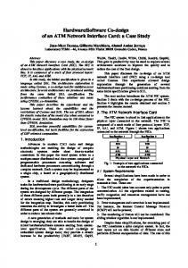
Table 1. An FSM table in a basic form
Previous_state_1 Previous_state_2 Previous_state_3 Previous_state_4
Input_1 New_state_1_1 New_state_2_1 New_state_3_1 New_state_4_1
when expected. But if the stuck key test is performed immediately thereafter, before the operator has released the key, that key will be detected as still down, i.e. stuck, causing a false failure of the stuck key test. Some delay between completing the sequence test and starting the stuck key test is obviously required, but such a delay was not defined in the requirements documents. We looked at the program code and noticed that the stuck key test is started as soon as any key goes up after the last key on the keyboard was pressed in sequence. If the key going up is the last key on the keyboard, all is fine, but if it is some other key, which is possible, a false failure of the stuck key test would occur. These possibilities highlighted the need to specify the criteria for completing of the sequence test and for starting the next test precisely, unambiguously and appropriately. The fact that this possibility had not caused false failures of keyboards in actual productive use of the program could be attributed to the layout of the keyboards and the way one swipes a finger over the keyboard during the test. However, this explanation does not apply to the layout of a new model keyboard being introduced. Thus, because of our disciplined approach, a possible problem was discovered before it arose in the production use of the program. In order to aid the decision making process, we wrote several specifications, each representing a different interpretation or assumption about the ambiguous or missing information.
4. Tabular representations of finite state machines specifications 4.1 Informal comments The FSM is a widely used model for describing computer systems and software. An FSM may be represented either by a graph in which each node represents a state and each edge represents a transition from one state to the next state or in a variety of tabular formats. In the approach illustrated below, each row in the table corresponds to a particular previous state, each column corresponds to a particular input value and the cell at the intersection of the row and the column contains the new state of the system. An example
Input_2 New_state_1_2 New_state_2_2 New_state_3_2 New_state_4_2
Input_3 New_state_1_3 New_state_2_3 New_state_3_3 New_state_4_3
of such a table with 3 inputs and 4 states is presented in Table 1. A similar table can describe the outputs of the machine, showing how they depend on values of states and inputs. FSMs arising in real systems often have a large number of states and inputs, making this type of table impractical. A more practical approach is to partition the states and inputs into classes characterised by predicate expressions, significantly reducing the size of the table. In the resulting table, each row corresponds to a group of previous states and each column corresponds to a group of inputs. The entries are expressions which evaluate to the next state. We used this approach to specify the STOP software. For the STOP software, the main component of the software state is the sequence number of the expected key. However, the behavior of the program also depends on whether or not an incorrect key or the escape key has been pressed previously. The state of the program is completely determined by the history of keystrokes. There are two possibilities (yes-no) for pressing an incorrect key and two possibilities for pressing the escape key so the total number of situations to consider is four times the number of keys in the sequence. In other words, we can partition all states into four groups where each group contains a state for every key. The inputs of the STOP software are described by the sequence number of the key pressed and can be divided into three main groups: an expected key, the escape key (only if not expected) and an incorrect (any other) key. The contents of these groups depend on the most recently passed key. The creation of FSM specifications for the sequence test of the STOP software is discussed in Section 4.2.
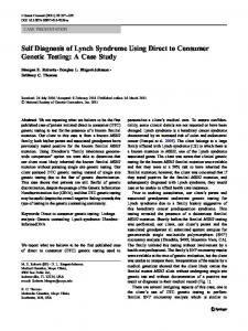
4.2 FSM tabular representation We created an FSM table for the STOP software using the following model: • Each intermediate state S of the test program is represented by a triple (n, w, e), where o n is the number of the expected key, o w � {T, F} indicates whether an incorrect key has been pressed and
Table 2. STOP software FSM tabular representation
Previous State S
k=n� n�L
k=n� n=L
k�n� k � esc � n=1
k�n� k � esc � n�1
k�n� k = esc
(n, F, F)
(n+1, F, F)
Pass
(n, T, F)
(n-1, T, F)
(n, F, T)
(n, F, T)
(n+1, F, F)
Pass
(n, T, F)
(n-1, T, F)
Fail
(n, T, F)
(n+1, F, F)
N/A
(n, T, F)
(n, T, F)
(n, T, T)
(n, T, T)
(n+1, F, F)
N/A
(n, T, F)
(n, T, F)
Fail
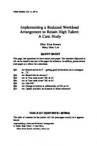
Table 3. FSM tabular representation with a multilevel header k=n
k�n
Previous State S
n�L
n=L
(n, F, F)
(n+1, F, F)
(n, F, T)
k � esc
k = esc
n=1
n�1
Pass
(n, T, F)
(n-1, T, F)
(n, F, T)
(n+1, F, F)
Pass
(n, T, F)
(n-1, T, F)
Fail
(n, T, F)
(n+1, F, F)
N/A
(n, T, F)
(n, T, F)
(n, T, T)
(n, T, T)
(n+1, F, F)
N/A
(n, T, F)
(n, T, F)
Fail
after this the expected key has not been pressed (in this situation w = T, otherwise w = F), o e � {T, F} indicates whether or not the most recently pressed key was the escape key (if it is the escape key, e = T, otherwise e = F). • k is the sequence number of the current input key. • ‘Pass’ and ‘Fail’ are final (absorbing) states, i.e. the result of the test program. • S 0 = (1, F, F) is the initial state of the model. • ‘esc’ is the sequence number of the escape key in the sequence keys of a keyboard (can be different for different types of keyboards). • L is the total number of keys on a keyboard including special buttons. The keys are numbered from 1 to L, so k and n take up any value in the set {1, ... L}. Table 2 gives a formal FSM representation of the STOP software behavior, which was informally de-
scribed in Section 2. Because the situations n = 1 and n = L require special consideration, the number of different groups of inputs increases. “N/A” corresponds to situations which cannot arise in reality because if w = T then n � L. As an output of the STOP program we consider the function, which returns the number of the expected key for all intermediate states and results of the test (‘Pass’ and ‘Fail’) for the final (absorbing) states. The output table can be easily derived from Table 2.
4.3 Representation header
with
a
multilevel
The conditions defining the columns of the table should partition the input space, i.e. they should be mutually exclusive and exhaustive. To make the partitions clearer and consequently reduce the number of mistakes, a modified version of the FSM table with a multilevel header was produced. To create a multilevel header, the whole input domain is first divided into two subdomains, forming level 1 of the header. Then each subdomain is divided
Table 4. FSM tabular representation with separated conditions Conditions n=1
1