We study the dynamics of two-phase flow with gravity and point ..... vertical communication; this timescale is determined roughly by the density differ- ence, fluid ...
c zzzz Institute for Scientific
Computing and Information
INTERNATIONAL JOURNAL OF NUMERICAL ANALYSIS AND MODELING Volume x, Number 0y, Pages 1–18
DISCUSSION OF DYNAMICS AND OPERATOR SPLITTING TECHNIQUES FOR TWO-PHASE FLOW WITH GRAVITY KNUT-ANDREAS LIE, JOSTEIN R. NATVIG, AND HALVOR MØLL NILSEN This paper is dedicated to the memory of Magne S. Espedal (1942–2010) Abstract.
We study the dynamics of two-phase flow with gravity and point
out three different transport mechanisms: non-cyclic advection, solenoidal advection, and gravity segregation. Each term has specific mathematical properties that can be exploited by specialized numerical methods. We argue that to develop effective operator splitting methods, one needs to understand the interplay between these three mechanisms for the problem at hand.
Key Words. operator splitting, Helmholtz decomposition, porous media flow
1. Introduction Numerical approximation of multiphase flow in heterogeneous reservoirs generally give rise to large systems of nonlinear equations that need to be solved to advance the solution forward in time. Developing a successful simulator therefore depends more on the robustness and efficiency of the nonlinear solvers than on the quality of the underlying discretization. This has led to widespread use of fully implicit formulations which promise unconditional stability. In practical simulations, however, robust implementations of fully implicit schemes must limit the length of the time step, depending on the complexity of the grid, the geology, fluid physics, discretization scheme etc. With increasingly large and complex reservoir descriptions, there is a growing demand for faster yet stable and predictable simulation technology. To achieve higher efficiency, solvers tend to exploit special features of the flow physics and possibly use some form of sequential operator splitting. The key idea of operator splitting for an evolutionary problem is to divide the model equations into a set of subequations that each model some parts of the overall dynamics that can be conquered using a simpler or more effective solution method. An approximation to the evolutionary solution is then constructed by solving the subequations independently, in sequence or parallel, and piecing the results together. Formally, we want to solve a Cauchy problem of the form (1)
dQ + A(Q) = 0, dt
Q(0) = Q0 ,
where A is an abstract and unspecified operator. The equation has the formal solution Q(t) = exp(−tA)Q0 . Assume now that we can write A = A1 + · · · + Am in some natural way and that we know how to solve the subequations (2)
dQ + Aj (Q) = 0, dt 1
j = 1, . . . , m
2
K.-A. LIE, J.R. NATVIG, AND H.M. NILSEN
more effectively that solving (1). Introducing a time step ∆t, and setting tn = n∆t, the operator splitting can formally be written as i h (3) Q(tn+1 ) = e−tn+1 A Q0 ≈ e−∆tAm · · · e−∆tA2 e−∆tA1 Q(tn ). Numerical methods are obtained by replacing the abstract operators e−∆tAj by numerical approximations. This way, one can combine numerical methods that have been developed to solve a particular class of evolutionary problems in a fairly straightforward manner, reusing specialized, highly efficient, and well-tested solvers. In particular, operator splitting enables easy replacement of one scheme with another scheme for the same elementary operator. Moreover, the use of operator splitting may also reduce memory requirements, increase the stability range, and even provide methods that are unconditionally stable. One of the first operator splitting methods used within reservoir simulation, was the alternating direction implicit (ADI) method [30, 11], in which multi-dimensional flow problems were successfully reduced to repeated one-dimensional problems that could be effectively solved using the Thomas algorithm. Today, this method is seldom used. Instead, it is common to use operator splitting methods that split the computation of flow and transport into separate steps, e.g., methods such as IMPES, IMPSAT, sequential splitting, and sequentially fully implicit. Such splittings are essential for the development of specialized and highly efficient methods like multiscale pressure solvers [13] and streamline methods [10]. Operator splitting is used not only to separate flow and transport, but may also be used to separate different physical effects within a transport (or flow) equation. In particular, many previous studies have focused on splitting methods for parabolic transport equations designed to effectively capture the balance and interaction of viscous and capillary forces, see [15, 20] and references therein. There are often several ways to decompose an evolution operator. A good starting point is to have effective and specialized solvers for parts of the problem, e.g., an effective pressure solver, an effective solver for advective flow, etc. Designing an optimal solution strategy, however, will also require a good understanding of how the different physical effects act together to form the overall dynamics of the problem so that one can: (i) optimize the operator decomposition into ’clean’ subproblems that can be solved as effectively as possible, and (ii) efficiently piece together the resulting subsolutions without creating undesired artifacts in the approximate solution. Moreover, operator splitting can be used to accommodate the intuitive principle that each physical effect should (ideally) be evolved using its appropriate time constant. In this paper, we discuss operator splitting for transport equations of the form � (4) φ∂t S + ∇ · f (S)~v + h(S, ~x)~g = q, involving only advective and gravitational forces. Our motivation for doing so is to understand how to utilize efficient advective solvers developed for the special case that the vector field is associated with potential flow and the hyperbolic characteristics of the system are always positive. The primary example is streamline simulation [10], but similar principles are used in methods for flow-based ordering [2, 23, 28]. In streamline simulation, the transport equation (4) is split into an advective and a gravity segregation part [18, 17, 7, 4] � � (5) φ∂t S + ∇ · f (S)~v = q, φ∂t S + ∇ · h(S, ~x)~g = 0.
DYNAMICS AND OPERATOR SPLITTING FOR TWO-PHASE FLOW WITH GRAVITY
3
If we let Aadv and Aseg denote the corresponding operators, approximate solutions of (4) can be constructed using the following operator splitting: h �n �m i (6) S(t + ∆t) ≈ Aseg (∆t/n) Aadv (∆t/m) S(t), where m and n are two positive numbers (in most cases n ≤ m). The transport mechanisms in the two equations in (5) act along curves in three-dimensional space that trace flow paths (streamlines and gravity lines, respectively) given by (7)
~v (~x) d~x = dτ φ(~x)
and
d~x ~g = . dr |~g |
Each equation can therefore usually be computed efficiently using Lagrangian coordinates. The advective equation has only positive characteristics (also for more complex models with more than two phases and/or components) and the singlepoint upwind method therefore gives a nonlinear triangular system with only one nonzero subdiagonal. Alternatively, one can use a highly efficient and unconditionally stable front-tracking method [19]. The segregation equation has both positive and negative characteristics along gravity lines and will in most cases also have a spatially discontinuous flux function. The standard approach within reservoir simulation is to use a mobility-weighted upwind approximation, in which the upwind direction is determined independently for each phase. This discretization is not always correct for discontinuous K; fortunately, the correct Godunov method is only slightly more complicated [27]. Alternatively, one can use an unconditionally stable front-tracking method for problems with spatially discontinuous flux [16]. The power of streamline methods is that streamlines change slowly in time compared to the dynamics of saturation fronts. For advection-dominated problems, streamline methods have been proven to be (significantly) more efficient than conventional methods [3, 31, 10]. Using streamlines involves a mapping from Eulerian to Lagrangian coordinates and back again, which may introduce numerical dissipation and lack of mass conservation [22]. To guarantee mass conservation, one may alternatively work directly in Eulerian coordinates and exploit unidirectional flow property of the advective flow equation to construct nonlinear Gauss–Seidel type iterations for implicit finitevolume discretizations [28, 29]. This may both increase the robustness and reduce the runtime significantly compared to standard (non)linear solvers A key design assumption in both streamline and flow-based ordering methods, is that the total velocity is close to a potential flow. If not, the total velocity field will contain a rotational component that may introduce large irreducible blocks in the nonlinear systems for finite-volume schemes [29] and cause streamlines to spiral or form loops. This will significantly deteriorate the efficiency of streamline and reordering methods, even if the rotational velocity component is orders of magnitude smaller than the advective part in most of the domain. To complicate matters, the rotational part of the velocity field is moving with the fluid since it is governed by the density difference. The main purpose of the paper is to discuss the dynamics of systems involving advective and gravitational forces. In particular, we are interested in systems having (large) density differences, e.g., as seen in simulation of CO2 storage. Through the use of two simple examples, we will show that more insight about the system behavior can be derived if one, instead of splitting the transport into advection and gravity segregation, considers all three different contributions to the dynamics: non-cyclic advection, solenoidal (rotational) advection, and gravity segregation. In
4
K.-A. LIE, J.R. NATVIG, AND H.M. NILSEN
particular, we show that the three different transport mechanisms in many cases occur at different timescales and hence can be exploited differently based on the understanding of the flow physics. Our qualitative analysis naturally suggests a general family of new splitting methods that isolate the rotational part of the velocity in separate splitting steps, thereby reducing its negative impact on the time step and the overall simulation efficiency. If all three steps are used, the new methods require an additional pressure solve with a different right-hand side to compute the solenoidal velocity, but the associated cost is low for many types of linear solvers since preprocessing, preconditioning, or factorizations of the coefficient matrix may be reused. However, only may also utilize disparity in timescales to design simpler splitting methods that achieve very high efficiency in special cases, e.g., if one of the steps can be assumed to take effect instantaneously. 2. Discussion of dynamics To keep the discussion as simple as possible, we consider incompressible flow of two immiscible fluids with different densities. The mathematical model is stated using a fractional flow formulation that separates the evolution into an elliptic flow equation for pressure and fluid velocity and a transport equation with strong hyperbolic characteristics for fluid saturations � � (8) ∇ · ~v = q, ~v + λK ∇p − (λw ρw + λn ρn )~g = 0 (9)
φ
∂Sw + ∇fw (~v + λn (ρw − ρn )K~g ) = qw . ∂t
Here, p is the fluid pressure, ~v is the total Darcy velocity, S is the saturation of the wetting phase, K and φ are the absolute permeability and porosity, respectively, ρα are the phase densities of the wetting (w) and non-wetting (n) phase, λα denote phase mobilities, and ~g is the acceleration of gravity. The total mobility, fractional flow, and source terms are defined by λ = λw + λn , f = λw /λ, and q = qw + qn , respectively. Throughout this paper, we use no-flow boundary conditions for each of the equations in (8) and (9). In the following, we will assume that the flow equation (8) can be solved (e.g., by a finite-volume method) to give a flux field with one scalar value vij associated with each interface between two cells i and j. The dynamics of the incompressible two-phase system is generally driven by three different mechanisms. To see this, we first use the fundamental theorem of vector calculus to introduce a decomposition of the total Darcy velocity that is reminiscent of a Helmholtz decomposition; that is, we write the velocity as a sum of a non-cyclic (curl-free) vector field and a solenoidal (divergence-free) vector field, ~v = ~vnc +~vrot . In our model, the non-cyclic and the solenoidal velocities satisfy the following pressure equations (10)
∇ · ~vnc = q,
~vnc + λK∇pnc = 0,
(11)
∇ · ~vrot = 0,
~vrot + λK∇prot = λK(λw ρw + λn ρn )~g .
We will later come back to how the two vector fields in the decomposition can be computed efficiently. Introducing the non-cyclic and the solenoidal velocities in the transport equation, we obtain the following equation h i (12) φ∂t Sw + ∇ fw (S)~vnc + fw (S)~vrot + fw (S)λn (S)(ρw − ρn )K~g = qw ,
DYNAMICS AND OPERATOR SPLITTING FOR TWO-PHASE FLOW WITH GRAVITY
5
from which we see that there are three different contributions to the flux: The first term, fw (s)~vnc , represents pure viscous forces driven by the gradient of a potential. If this is the only flux contribution, the transport equation (12) will have a unidirectional flow property (or causality principle) which ensures that perturbations travel along streamlines from fluid sources or inflow boundaries to fluid sinks or outflow boundaries. If the fluxes are computed from (10) using a monotone method, no streamlines will reenter a grid cell they have passed through earlier. In this case, the transport equation can be discretized using a standard single-point upwind discretization (13)
Φ(S n+1 − S n ) + ∆tV f (S n+1 ) = q.
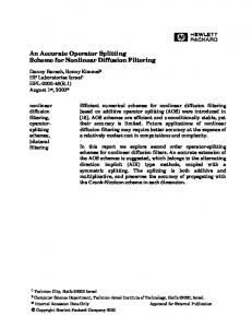
Here, Φ = diag(φi ) where φi is the porosity in cell i, S is the vectors of volumeaverage saturations per cell, f the vector of fractional flow values per cell, q the fluid sources per cell, and V is the the upwind flux matrix. A particularly efficient solver can be developed by observing that the directed graph formed by considering grid cells as vertices and the fluxes over each cell interface as directed edges is acyclic and can be flattened by a topological sort. Using this reordering, the upwind flux matrix can be rearranged to a lower triangular form by a symmetric permutation of the rows and columns using Tarjan’s algorithm [12]. Hence, the nonlinear system (13) can be computed using a highly efficient nonlinear Gauss–Seidel approach, in which the solution is computed cell-by-cell (using e.g., Ridder’s method), see [28] for more details.. The second term, fw (S)~vrot , represents gravity-induced advection, which has a circular behavior similar to that of a convection cell. When ~vrot is nonzero, the directed graph associated with the total velocity will generally not be acyclic and may contain cycles consisting of cells that have a circular dependence in (13). In the worst case, streamlines may also be cyclic and reenter cells they have passed through earlier. The cycles are easy to detect using a topological sort of the reverse flux graph and once they are detected, the nonlinear system in (13) can be rearranged into a block-triangular form with circularly dependent cells appearing as matrix blocks on the diagonal. A nonlinear Gauss–Seidel algorithm may still be used to solve (13), but now the local block systems must be solved using a Newton– Raphson type method, which may significantly affect the overall efficiency of the overall method. The rotational contribution to the total velocity depends upon the saturation distribution, and the larger this contribution is, the tighter the coupling will be between the flow and the transport equation. The third flux term in (12) represents gravity segregation that acts along onedimensional lines parallel to the gravity vector ~g . Along each such gravity line, the characteristics will generally point in both directions corresponding to the lighter fluid moving upwards and the heavier fluid moving downwards. In streamline and other related methods, the gravity step is therefore typically accounted for in a separate step [18, 17, 7, 4]. We will come back to such operator splittings in the next section. First, however, we consider an example that illustrates the non-cyclic and rotational parts of the dynamics. Example 1. Consider two fluids with densities 100 and 1000 Kg/m3 , linear relative permeability curves, and viscosities equal 1 cP for both fluids. The domain is homogeneous with permeability 100 mD covering the unit square. In the upper-right corner, a fluid source injects the lighter fluid at a rate of 0.01 m3 /day, whereas fluid is produced at the same rate from a sink in the lower-left corner. Initially, the saturation of the light fluid is zero in the whole domain. The injection of fluid result
6
K.-A. LIE, J.R. NATVIG, AND H.M. NILSEN
in a flow that is driven by a linear combination of buoyancy forces and a pressure gradient, but with a strong buoyancy dominance. Figure 1 shows the saturation field and the decomposition of the total Darcy velocity. We observe that the strength of the solenoidal component increases as more light fluid enters the domain. Let us now reverse the flow and inject the light fluid in the lower-left corner and produce fluids from the upper-right corner. Moreover, to increase the influence of gravity we reduce the injection rate to 0.001 m3 /day. Figure 2 shows the saturation field, the total velocity, the solenoidal velocity, and the cells that are part of a cycle in the directed flux graph and hence mutually dependent. (The non-cyclic velocity is identical to the one shown in Figure 1 and is therefore not plotted.) Here, the advective flow that is imposed by the source-sink pair is so weak that the flow is almost fully segregated. A sharp interface forms between the fluids with a corresponding jump in density that yields a strong solenoidal contribution to the total velocity field. As a result, we observe that large irreducible blocks form when the light fluid accumulates at the top boundary. After one hundred days, 89 of 400 grid cells are connected in one irreducible diagonal block. This will significantly reduce the efficiency of a nonlinear Gauss–Seidel method. After three hundred days, there are two irreducible blocks with 341 grid cells in the first block and four cells in the second. The example above shows that the rotational part may give a significant contribution to the total velocity field for cases with large density differences. The appearance of loops and spirals in the velocity field is inconvenient when tracing streamlines, e.g., because one often ends up discarding such streamlines, or alternatively, needs to impose periodic boundary conditions in the 1D transport solver. This makes the solution of transport along streamlines unappealing in regions dominated by gravity. Similarly, the efficiency of nonlinear Gauss–Seidel solvers is reduced when there are large loops in the velocity field, for which all the corresponding unknowns in (13) must be solved for simultaneously. In fact, since optimal ordering is based on a reduction of the flux matrix V in (13) to (block)triangular form using a topological sorting algorithm [28, 29, 12], the algorithm is sensitive to small reverse fluxes that are caused by gravitational effects. In the next example, we will illustrate how timescales of the three different transport mechanisms and hence the overall system dynamics are affected by heterogeneity and anisotropy in the permeability field. Example 2. We consider a vertical cross-section of a reservoir described by a 220 × 85 Cartesian grid with petrophysical parameters sampled from the first xzslice of Model 2 from the SPE 10 benchmark [8]. The reservoir is initially filled with a fluid with density 1000 Kg/m3 into which a lighter fluid with density 100 Kg/m3 is injected at a constant rate of one pore volume per 20 000 days from a source evenly distributed in the grid cells at the left boundary. On purpose, the density difference is large and the injection rate is small to exaggerate the effects of gravity. Reservoir fluids are produced by a sink evenly distributed in the cells along the right boundary. The fluid mobilities are specified using Corey-type relative permeabilities with exponent two and a viscosity of 1 centi Poise for both fluids. For simplicity, we set gravity to 10 m/s2 . For the porosity, we use a lower cut-off value of 0.001. We consider two permeability realizations: the first is isotropic and uses only Kx from the original model, whereas the second uses the original, anisotropic (Kx , Kz ) permeability field. Figure 3 shows the solution for the isotropic model after 5 000 and 10 000 days. From the streamline plots, we see that the velocity field is quite irregular and that the local direction of flow changes with time. This is reflected in
DYNAMICS AND OPERATOR SPLITTING FOR TWO-PHASE FLOW WITH GRAVITY
total velocity ~v
non-cyclic ~vnc
rotational ~vrot
t=12 days
t=1 day
saturation
Figure 1. Buoyancy-dominated flow in a homogeneous domain with a light fluid injected into a heavy fluid. total velocity ~v
rotational ~vrot
cells in cycles
t=300 days
t=100 days
t=20 days
saturation
Figure 2. Buoyancy-dominated flow in a homogeneous domain with a light fluid injected into a heavy fluid from the lower-left corner. In the left column, cells involved in a cycle are colored red whereas cells that can be computed independently in sequence are colored yellow.
7
8
K.-A. LIE, J.R. NATVIG, AND H.M. NILSEN
t=5 000 days
t=10 000 days
Figure 3. Constant rate injection in all layers of a vertical crosssection with isotropic permeability. The plots show the saturation of the injected fluid (top), streamlines of the total velocity (middle), and the strongly connected grid cells in red (bottom). t=5 000 days
t=10 000 days
Figure 4. Constant rate injection in all layers of a vertical crosssection with anisotropic permeability.
the plot of cells that belong to strongly connected components in the corresponding directed flux graph; the loops seem to follow the saturation fronts. It is worth noting that for a loop to appear in the total velocity, the strength (or timescale) of the non-cyclic advection and the solenoidal advection must locally be of the same magnitude. For higher injection rates, the non-cyclic advection will have a shorter timescale than the solenoidal advection for the domain as a whole. The timescales for the different parts of the dynamics are reported in the upper part of Table 1. Figure 3 shows the corresponding solutions for the anisotropic model. In this case, the vertical permeability is significantly smaller than the horizontal permeability; more than half of the cells have a large anisotropy ratio (Kx /Kz in the range of 104 ), which presumably models shale layers. This is reflected in a total velocity
DYNAMICS AND OPERATOR SPLITTING FOR TWO-PHASE FLOW WITH GRAVITY
9
Table 1. The maximal time step in days for an explicit method for different parts of the dynamics of the transport equations for the two models of Example 2. Model isotropic anisotropic
Time (days)
Non-Cyclic
Rotational
Segregation
5 000 10 000 5 000 10 000
5.0 5.0 24 31
89 95 7 700 7 000
0.23 0.48 0.75 0.75
less affected by gravity, with fewer and smaller loops. From the lower part of Table 1 we see that the timescale of segregation is only slightly increased by the reduced vertical communication; this timescale is determined roughly by the density difference, fluid viscosity, and the largest z-permeability. The timescale for the solenoidal advection, on the other hand, is significantly increased because of the shale layers that dramatically decreases the effective permeability along any closed streamline. As a consequence, the number of loops in the total velocity field is reduced; it is unlikely that the local timescales for non-cyclic advection and solenoidal advection are of the same magnitude. However, we remark that in a three-dimensional model, where the pressure gradient and velocity will decrease with distance from the wells, these timescales will likely be of the same magnitude in some parts of a reservoir even in the presence of small vertical permeability. 3. Improved operator-splitting methods In the previous section, we argued how the presence of rotational components in the total velocity will reduce the efficiency of the nonlinear Gauss–Seidel method for the advective part. Likewise, loops or spirals will complicate tracing of streamlines as well as setting appropriate boundary conditions for the one-dimensional transport equations along each streamline. To remedy these problems, and to accommodate that the gravity segregation and the non-cyclic and solenoidal advection may occur on different time scales, we split the advection into two subequations and end up with three transport equations � (14) φ∂t S + ∇ · fw (S)~vnc = qw , � (15) φ∂t S + ∇ · fw (S)~vrot = 0, h i (16) φ∂t S + ∇ fw (S)λn (S)(ρw − ρn )K~g = 0 If we let Anc , Arot , and Aseg denote the corresponding operators, approximate solutions of (9) can be constructed using the following three-step operator splitting: h �n �m �` i (17) S(t + ∆t) ≈ Aseg (∆t/n) Arot (∆t/m) Anc (∆t/`) S(t), where m, n, and ` are three positive numbers. The main advantages of (17) are that each subequation is solved using an optimal scheme with an optimal time step, and that the rotational part of the velocity is removed from the advective velocity to enable the use of highly efficient schemes available for non-cyclic flows. There are, of course, many other ways to sequence the operators to better preserve the interaction of the three physical mechanisms. For instance, the order of Aseg and Arot can be interchanged or the operators can be combined if one does not want to exploit the one-dimensional structure of (16).
10
K.-A. LIE, J.R. NATVIG, AND H.M. NILSEN
Figure 5. Realistic reservoir model from offshore Norway. The plot shows the saturation field after ten years of water injection, computed using equally-spaced pressure steps of length 2.5 years. The operator splitting (17) assumes that the pressure equation is solved twice with different right-hand sides (see (10) and (11)). Fortunately, this is not twice as expensive as solving (8). First of all, we only have to generate the system matrix once. Furthermore, any preconditioning or factorization of the system matrix may be reused for the second pressure solve. It is also worth noting that the coupling between the pressure equation and the saturation equation through saturationdependent mobilities can be quite severe in regions where the flow is dominated by gravitational effects. In these regions, the velocity field changes as fast as the saturation fronts move. By splitting the velocity field in a non-cyclic part and a rotational part, we can quantify the degree with which the gravitational effects induce tighter coupling in the operator splitting. In the rest of this section, we present numerical experiments that illustrate the use of operator splitting on two representative models, by also shows the importance of understanding the dynamics of the problem when applying operator splitting. The emphasis of our first example is to demonstrate that the new gravity splitting is applicable to realistic reservoir models with complex, twisted, and deformed grid cells; sealing and partially sealing faults; thin and eroded layers; barriers, etc. Example 3. The model in this example is based on a real-field model from offshore of Norway. We use the original geology and reservoir geometry, described as a corner-point grid with approximately 44 000 active cells, but have modified the fluids and wells. We have filled the original gas cap with oil to make the model more suitable for an incompressible formulation. Initially, the reservoir is in near hydrostatic equilibrium with the original oil-water contact preserved. We inject water in some of the original wells. Furthermore, we use Corey relative permeability curves with Corey exponent four and viscosities 0.318 cP and 1 cP for oil and water, respectively. The density difference used is 174 kg/m3 . Figure 5 shows the water saturation after ten years of injection. Our first objects of interest are the timescales associated with gravity segregation and non-cyclic and rotational advection. Table 2 reports the maximum time step fulfilling a CFL restrictions for the three substeps. We see that the non-cyclic advection step has the most severe time-step restriction, whereas the maximal time steps for the gravity segregation and rotational advection are one and two orders of magnitude higher, respectively; the upper bound on the rotational step increases with time, but stabilizes around 200 days for longer times.
DYNAMICS AND OPERATOR SPLITTING FOR TWO-PHASE FLOW WITH GRAVITY
11
Table 2. Estimated time step restrictions for each of the splitting steps (14), (15), and (16) for the model shown in Figure 5. Time (years) Anc (days) Arot (days) Aseg (days)
0.25 1 46 6
0.5 1 79 6
0.75 1 82 6
1.0 1 85 6
1.25 1 87 6
2.5 1 120 6
5.0 1 200 6
7.5 1 213 6
Table 3. Number of cycles (N ), number of cells in the largest cycle (max), and the total number of cells involved in cycles for the model in Figure 5 for fluxes computed with a two-point method with pressure steps ∆t equal 2.5 and 0.25 years. ∆t years 2.5
0.25
Time years 2.5 5 7.5 0.25 1.0 2.0 2.25
N 26 27 13 9 8 9 9
~vrot max 37835 38912 39913 31709 36763 37856 38092
#cells 38133 39390 40820 32489 36920 38002 38246
N 18 10 15 34 22 19 20
~v = ~vnc + ~vrot max #cells 188 410 178 356 186 404 443 728 202 594 195 563 193 570
In our opinion, the table shows that it may be feasible to use explicit transport solvers for this model: a step length of six days for the segregation is not too bad, and a step length of one day is close to acceptable for the (non-cyclic) advective step. On the other hand, the model resolution is quite coarse, in particular near the wells, and a further lateral refinement in the near-well regions would worsen the restriction on the advective step, but not affect the gravity step significantly. Next, we consider the possibility of accelerating implicit temporal discretizations using a nonlinear Gauss–Seidel method. As a measure of the complexity of the nonlinear problem, we report some statistics on the cycles that appear in the flux graph, or more precisely, the number and size of the irreducible diagonal blocks in the upwind flux matrix V from (13). The irreducible blocks are identified by permuting V to a block-diagonal form using Tarjan’s algorithm [12]. Table 3 reports the number of cycles, the number of cells in the largest cycle, and the total number of cells involved in cycles observed for two different sizes of the pressure step. These quantities give a good picture of the difficulties of the nonlinear problem which would ultimately limit the efficiency of implicit methods for long time steps. If the flux is computed using a monotone two-point flux-approximation scheme, there are no cycles in the flux field corresponding to ~vnc , whereas the total velocity has 400–500 cells involved in cycles. Isolating the rotational component in a separate step will therefore improve the efficiency of the advective step. The rotational velocity, has cycles covering almost the complete domain, but may be solved efficiently using a single explicit step because of the large time constant. In general, having as few cycles as possible is highly favorable when using a streamline or a nonlinear Gauss–Seidel method to accelerate the advective step. So far, we have only considered a two-point scheme for solving the pressure equation(s). It is well-known that this scheme is inconsistent and hence ill-suited for rough geometries or strongly anisotropic permeability tensors. If one, on the other
12
K.-A. LIE, J.R. NATVIG, AND H.M. NILSEN
Table 4. Number of cycles (N ), number of cells in the largest cycle (max), and the total number of cells involved in cycles for the model in Figure 5 for fluxes computed with a mimetic method with pressure step of 0.25 years. Time years 0.25 0.50
N 424 433
~vnc max 3314 3268
#cells 9038 9514
N 98 76
~vrot max 33451 36277
#cells 35314 37720
N 453 423
~v = ~vnc + ~vrot max #cells 2245 8697 3274 10272
hand, uses a convergent scheme, such a multipoint or mimetic method, one will inevitably obtain flux fields with cycles, even without gravity as for ~vnc in (10). There seems to be a close relation between cycles in the velocity field and monotonicity of the pressure, see e.g., Figure 8 in [24]. Unfortunately, unless certain assumptions are imposed on the underlying grid and permeability field or both, there exists no (convergent) monotone method with local stencil that guarantees monotone pressure [21]. On the other hand, our experience is that non-convergent, monotone methods guarantee loop-free velocity fields. In Table 4 we report the same statistics as in Table 3 for the flux computed by a mimetic scheme for (10). In this case, the number of cycles produced by the mimetic scheme is approximately the same as the number of cycles introduced by the solenoidal contribution in Table 3. Based on the combined results reported in Tables 2 and 3, a good operatorsplitting approach would be to use (17), solving (14) implicitly to approximate Anc and (15) explicitly to approximate Arot . In the following, we present a simplified analysis that indicates that this observation may indeed be valid for many other cases. We start by considering the segregation step, where the maximal time step allowed by the CFL condition is given by � � � d � (18) tseg ∼ ∆z/ Kz |~g |∆ρ λo (S)fw (S) φ . dS Here, ∆ρ is the difference in densities and Kz is the vertical permeability. The solenoidal step depends upon the particular distribution of the fluid which decides the gravity-driven contribution of the total velocity. A useful estimate of the fluid distribution can be derived based upon the Dupuit approximation which is commonly used in vertical-equilibrium models [5, 26, 9]. Assuming that the light fluid is confined to a thin layer of height h under a horizontal top surface of the aquifer gives the following time step due to motion in the x direction, � ∆ρ ∂h � (19) txrot ∼ ∆x/ Kx |~g | φ , µ ∂x where Kx is the lateral permeability (in the x-direction) and µ is the viscosity of the light fluid. From the same equation we can find the maximal time step associated with vertical flow � ∆ρ ∂ 2 h2 � (20) tzrot ∼ ∆z/ Kx |~g | φ . 2µ ∂ 2 x The ratio between these two estimates is ∂ 2 h2 � ∂h � ∆xH (21) txrot /tzrot ∼ ∆x 2 / 2∆z ∼ . ∂ x ∂x ∆zL Here, H denotes a typical vertical length scale while L denotes a horizontal length scale. For most reservoir models, this ratio would be greater than one. We also
DYNAMICS AND OPERATOR SPLITTING FOR TWO-PHASE FLOW WITH GRAVITY
13
Figure 6. The Johansen model. The left plot shows a height map of the top surface, whereas the right plot shows the CO2 distribution 500 years after the injection start. notice that this ratio does not depend on Kz . The ratio of the segregation step to the rotational step is � � ∆zKx H ∂h � d � (22) tseg /txrot ∼ Kx ∆z / Kz ∆x λo fw µ ∼ . ∂x dS ∆xKz L If we assume that Kx /Kz ∼ 10, ∆x/∆z is in the range 50–100, and that H/L ∼ 100, the ratio will be between 0.1 and 0.2. In Table 2 of Example 3, we observed that the ratio is 0.1, or less, which suggests that the rotational velocity for many models can be treated explicitly. When this is the case, the rotational step will be relatively inexpensive to compute compared to the advection and segregation steps. (A similar scaling would be expected also in cases for which the Dupuit approximation is not valid because the length scale of the lateral variation in most cases is longer than the vertical scale of a reservoir.) In the previous example, we considered a real model of a petroleum reservoir having dynamics dominated by viscous forces (injection and production wells). In the next example, we consider another real-life example which is dominated by gravity segregation. Example 4. The Johansen formation is a deep saline aquifer in the North Sea which is evaluated as a potential storage for CO2 in a future pilot project for CCS at Mongstad, Norway [14, 6]. We consider the sector model ’NPD5’ [1] consisting of the lower three geological zones of Johansen, which cover an area of approximately 50 × 50 km2 . The left plot in Figure 6 shows a height-map of the sector model with an injection well indicated. The simulation setup is as follows: 3.5 Mt of CO2 is injected yearly for 110 years, and we study the migration for a post-injection period of 390 years. We use a fluid model similar to what was used in the previous study by Eigestad et al. [14]. The fluid properties are reference values for CO2 and brine taken at 300 bar. At this pressure, the approximate viscosity and density of supercritical CO2 are 0.057 cP and 686.54 kg/m3 , respectively, while for brine the viscosity and density are 0.30860 cP and 975.86 kg/m3 . Residual trapping is accounted for by setting a residual saturation of 0.2 for CO2 and 0.1 for brine. The right plot shows the CO2 distribution 500 years after the start of injection. The upper half of Table 5 reports representative maximal time steps for the noncyclic advection, the rotational advection, and the gravity segregation. During the
14
K.-A. LIE, J.R. NATVIG, AND H.M. NILSEN
Table 5. The maximal time step in years for an explicit method for different parts of the dynamics of the transport equations for the Johansen formation for the 3D model in (8)–(9) and the vertical equilibrium (VE) model in (23)–(24). Model
Time
3D
injection post injection injection post injection
VE
Advection
Rotation
Segregation
Parabolic
0.1 — 1 —
10 12 201 164
0.04 0.04 8 8
— — 6 3
injection period, the dynamics of the problem is dominated by the interplay of noncyclic advection and gravity segregation, i.e., as in the upper plots of Figure 2 in Example 1. Because of the large density difference between the injected CO2 and the resident brine, the time constant is lower for the gravity segregation than for the non-cyclic advection. Still, the operator splittings (6) and (17) are quite applicable, using either streamlines or a 3D finite-volume method with a nonlinear Gauss-Seidel solver for the advective part. When injection is terminated, the viscous advection disappears, leaving the rotational advection and gravity segregation as the main effects. Because of the large disparity in time constants, it does not make sense to apply an operator splitting. Instead, one can as a good approximation assume that gravity segregation reaches vertical equilibrium instantaneously, as in the Dupuit approximation discussed above. This means that the flow of a layer of CO2 can be approximated in terms of its thickness to obtain a 2D simulation model. The vertical-equilibrium (VE) formulation for (8)–(9) can be written in a standard fractional flow formulation as a system consisting of a pressure and a transport equation: h � � i λw ∇k · ~v = qtot , ~v = −λt ∇k pt − fv ρco2 + [1 − fv ]ρw ~gk + (23) ∇k gc λt � � �� ∂s (24) + ∇k fv (s, x)~v + fg (s, x) ~gk + ∇k gc (s, x) = q(x) ∂t Here, s = h/H is the ratio between the height h of the CO2 column and the total formation height H, pt is the pressure along the top surface, and subscripts k and ⊥ denote parallel to and perpendicular to the top surface. Moreover, to illuminate the similarity with the standard two-phase flow model, we introduce pseudo mobilities, fractional flows, and ’capillary terms’ given by Z sH Z H λco2 (s, x) = kco2 (1)Kx (z, x)dz, λw (s, x) = kw (1)Kx (z, x)dz, 0
(25)
sH
λco2 (s, x) , fg (s, x) = λw (s, x)fv (s, x), fv (s, x) = λco2 (s, x) + λw (s, x) gc (s, x) = s(ρco2 − ρw )g⊥ .
As in (10) and (11), the pressure equation (23) can be decomposed into non-cyclic and solenoidal subequations. Likewise, the flux terms in (24) can be separated into viscous advection, rotational forces, gravity segregation, and a parabolic ’capillary’ term. The corresponding time constants are reported in the lower half of Table 5.
REFERENCES
15
Comparing the upper and lower parts of Table 5 shows why vertical equilibrium simulations may be attractive to increase (lateral) resolution while saving computational cost. Although this approach reduces the dimension of the model, important information of the heterogeneities in the underlying 3D medium is preserved. Indeed, in many cases the errors resulting from the VE assumption may be significantly smaller than the errors introduced by the overly coarse resolution needed to make the 3D simulation model computationally tractable. A more thorough discussion of VE simulations of the Johansen formation is given, e.g., by Ligaarden and Nilsen [25]. 4. Concluding remarks In this paper we have analyzed the dynamics of a simple two-phase model and shown that it is governed by three different physical mechanisms: (non-cyclic) viscous advection, rotational (gravity-induced) advection, and gravity segregation. All three mechanisms act along curves in three-dimensional space: rotational advection acts along closed curves whereas viscous advection and gravity segregation act along curves that start and terminate at fluid sources/sinks or the boundary of the domain. Based on our analysis of the dynamics, we suggest a new family of splitting methods in which the rotation-free advective transport is separated from the dynamics due to gravity. With the proposed methods, it may be possibility to improve gravity splitting schemes that use methods fine-tuned for advective flow, such as streamline methods or methods employing causality-based reordering. In our experiments, we have used a decomposition of the continuous equations to show that the proposed splitting isolates the dynamics associated with gravity in an efficient manner. The decomposition can also be used to analyze the utility of operator splitting methods that seek to utilize effective advection and/or segregation solvers. To guarantee that the discrete fluxes corresponding to ~vnc are completely noncyclic, the continuous decomposition requires monotone pressure solutions, which are difficult to obtain for consistent discretizations [21]. An efficient discrete operator splitting should therefore be based on decomposing the discrete flux matrix rather than the continuous equations since such a decomposition would eliminate cycles introduced both by the rotational transport mechanism and the discretization of the pressure equation(s). Finding such a discrete decomposition is a topic for future research. Acknowledgments This research was funded in part by the Research Council of Norway through grants no. 178013 and 186935. References [1] URL http://www.sintef.no/Projectweb/MatMorA/Downloads/Johansen. [2] J. R. Appleyard and I. M. Cheshire. The cascade method for accelerated convergence in implicit simulators. In European Petroleum Conference, pages 113–122, SPE 12804, 1982. doi: 10.2118/12804-MS. [3] R. Baker. Streamline technology reservoir history matching and forcasting = its success limitations, and future. JCPT, 40(4):23–27, 2001. [4] R. Batycky, M. J. Blunt, and M. R. Thiele. A 3d field scale streamline simulator with gravity and changing well conditions. SPE, 12(4):246–254, 1997. [5] J. Bear. Dynamics of Fluids in Porous Media. Dover, 1988.
16
REFERENCES
[6] P. E. S. Bergmo, E. Lindeberg, F. Riis, and W. T. Johansen. Exploring geological storage sites for CO2 from Norwegian gas power plants: Johansen formation. Energy Procedia, 1(1):2945 – 2952, 2009. ISSN 1876-6102. doi: 10.1016/j.egypro.2009.02.070. [7] F. Bratvedt, T. Gimse, and C. Tegnander. Streamline computations for porous media flow including gravity. Transp. Porous Media, 25(1):63–78, oct 1996. doi: 10.1007/BF00141262. [8] M. A. Christie and M. J. Blunt. Tenth SPE comparative solution project: A comparison of upscaling techniques. SPE Reservoir Eval. Eng., 4:308–317, 2001. Url: http://www.spe.org/csp/. [9] K. H. Coats, J. R. Dempsey, and J. H. Henderson. The use of vertical equilibrium in two-dimensional simulation of three-dimensional reservoir preformance. Soc. Pet. Eng. J., Mar:68–71, 1971. [10] A. Datta-Gupta and M. J. King. Streamline Simulation: Theory and Practice, volume 11 of SPE Textbook Series. Society of Petroleum Engineers, 2007. [11] J. Douglas, Jr. and H. H. Rachford, Jr. On the numerical solution of heat conduction problems in two and three space variables. Trans. Amer. Math. Soc., 82:421–439, 1956. [12] I. S. Duff and J. K. Reid. An implementation of Tarjan’s algorithm for the block triangularization of a matrix. ACM Trans. Math. Software, 4(2):137–147, 1978. [13] Y. Efendiev and T. Y. Hou. Multiscale Finite Element Methods, volume 4 of Surveys and Tutorials in the Applied Mathematical Sciences. Springer Verlag, 2009. [14] G. Eigestad, H. Dahle, B. Hellevang, F. Riis, W. Johansen, and E. Ø ian. Geological modeling and simulation of CO2 injection in the Johansen formation. Comput. Geosci., 13(4):435–450, 2009. doi: 10.1007/s10596-009-9153-y. [15] M. S. Espedal and K. H. Karlsen. Numerical solution of reservoir flow models based on large time step operator splitting algorithms. In Filtration in porous media and industrial application (Cetraro, 1998), volume 1734 of Lecture Notes in Math., pages 9–77. Springer, Berlin, 2000. [16] T. Gimse and N. H. Risebro. Solution of the Cauchy problem for a conservation law with a discontinuous flux function. SIAM J. Math. Anal., 23(3):635–648, 1992. [17] R. H. J. Gmelig Meyling. Numerical methods for solving the nonlinear hyperbolic equations of porous media flow. In Third International Conference on Hyperbolic Problems, Vol. I, II (Uppsala, 1990), pages 503–517, Lund, 1991. Studentlitteratur. [18] R. H. J. Gmelig Meyling. A characteristic finite element method for solving non-linear convection-diffusion equations on locally refined grids. In D. Guerillot and O. Guillon, editors, 2nd European Conference on the Mathematics of Oil Recovery, pages 255–262, Arles, France, Sept 11-14 1990. Editions Technip. [19] H. Holden and N. H. Risebro. Front Tracking for Hyperbolic Conservation Laws, volume 152 of Applied Mathematical Sciences. Springer-Verlag, New York, 2002. ISBN 3-540-43289-2. [20] H. Holden, K. H. Karlsen, K.-A. Lie, and N. H. Risebro. Splitting methods for partial differential equations with rough solutions: Analysis and MATLAB programs. EMS Series of Lectures in Mathematics. European Mathematical Society (EMS), Z¨ urich, 2010. doi: 10.4171/078.
REFERENCES
17
[21] E. Keilegavlen, J. M. Nordbotten, and I. Aavatsmark. Sufficient monotonicity criteria are necessary for control volume methods. App. Math. Lett., 22(8): 1178–1180, 2009. doi: 10.1016/j.aml.2009.01.048. [22] V. Kippe, H. Hægland, and K.-A. Lie. A method to improve the mass-balance in streamline methods. In SPE Reservoir Simulation Symposium, Houston, Texas, U.S.A, 26–28 February 2007. SPE 106250. [23] F. Kwok and H. Tchelepi. Potential-based reduced newton algorithm for nonlinear multiphase flow in porous media. J. Comput. Phys., 227(1):706–727, 2007. Doi: 10.1016/j.jcp.2007.08.012. [24] K.-A. Lie, S. Krogstad, I. S. Ligaarden, J. R. Natvig, H. M. Nilsen, and B. Skaflestad. Open source MATLAB implementation of consistent discretisations on complex grids. Comput. Geosci., 2011. doi: 10.1007/s10596-0119244-4. [25] I. S. Ligaarden and H. M. Nilsen. Numerical aspects of using vertical equilibrium models for simulating CO2 sequestration. In Proceedings of ECMOR XII–12th European Conference on the Mathematics of Oil Recovery, Oxford, UK, 6–9 September 2010. EAGE. [26] J. C. Martin. Some mathematical aspects of two phase flow with application to flooding and gravity segregation. Prod. Monthly, 22(6):22–35, 1958. [27] S. Mishara and J. Jaffr´e. On the upstream mobility scheme for two-phase flow in porous media. Comput. Geosci., 14(1):105–124, 2010. [28] J. R. Natvig and K.-A. Lie. Fast computation of multiphase flow in porous media by implicit discontinuous Galerkin schemes with optimal ordering of elements. J. Comput. Phys., 227(24):10108–10124, 2008. doi: 10.1016/j.jcp.2008.08.024. [29] J. R. Natvig and K.-A. Lie. On efficient implicit upwind schemes. In Proceedings of ECMOR XI, Bergen, Norway, 8–11 September. EAGE, 2008. [30] D. W. Peaceman and H. H. Rachford, Jr. The numerical solution of parabolic and elliptic differential equations. J. Soc. Indust. Appl. Math., 3:28–41, 1955. [31] M. Thiele. Streamline simulation. In 8th International Forum on Reservoir Simulation, Stresa / Lago Maggiore, Italy, 20–24 June 2005. SINTEF, Department of Applied Mathematics, PO Box 124 Blindern, NO-0314 Oslo, Norway E-mail: {Knut-Andreas.Lie, Jostein.R.Natvig, Halvor.M.Nilsen}@sintef.no URL: http://folk.uio.no/kalie