Distributed Delay Estimation and Call Admission Control in IEEE 802.11 WLANs Kenta Yasukawa1
Andrea G. Forte and Henning Schulzrinne
Department of Communications and Integrated Systems Tokyo Institute of Technology
[email protected]
Department of Computer Science Columbia University {andreaf,hgs}@cs.columbia.edu
Abstract—Voice over WiFi (VoWiFi) will soon be the main alternative to cellular phones. Providing a satisfactory user experience remains difficult, however. We focus on Call Admission Control (CAC) for both Constant Bit Rate (CBR) and Variable Bit Rate (VBR) VoIP traffic. Our approach is based on measuring the time between idle times. It requires no infrastructure changes, adds no probing traffic and has low complexity. We demonstrate through extended simulations that our approach achieves very good accuracy for both delay estimation and CAC when only VoIP sources are present and when both VoIP sources and data sources are present. Furthermore, we confirm TBIT performance through experiments. Index Terms—Call Admission Control, Delay Estimation, IEEE 802.11, VoIP, VBR, CBR.
I. I NTRODUCTION In recent years VoIP and IEEE 802.11 networks have seen a rapid growth. In IEEE 802.11 networks, an Access Point (AP) and the stations (STAs) it serves form a Basic Service Set (BSS). Each AP can support a limited number of concurrent voice calls; we refer to this number as the AP capacity. After the number of concurrent voice calls in the BSS surpasses the AP capacity, the communication of all users at that AP suffers from high delay and high collision rate, and therefore, poor quality. The situation becomes even worse in scenarios where both voice traffic and data traffic are present. In this last case, the AP capacity for VoIP becomes even smaller since part of the bandwidth is now used by data traffic. These are the kinds of problems we address with CAC. In particular, a good CAC mechanism needs to recognize when the AP capacity has been reached and either redirect STAs to associate to a non-congested AP or defer their call attempt. In this paper we propose a mobile-station-based CAC mechanism. One of the strengths of the proposed approach is that it is very simple and yet accurate, while not requiring any probing of the medium. Our approach is entirely client-based, thus not requiring any changes in the infrastructure and the protocol. The proposed mechanism is based on the idea that any STA in the BSS can monitor the shared medium and calculate the time between idle times (TBIT), focusing on the level of congestion seen by the AP. By using TBIT each STA can make CAC decisions autonomously. 1 Work
performed while at Columbia University.
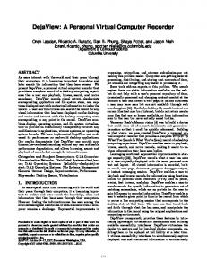
Busy Medium
Fig. 1.
SIFS
DIFS
...
Data Frame
ACK
Random Backoff Slots [0, CW) IEEE 802.11 Medium access procedure using DCF
We focus on the congestion seen by the AP because the AP has to send packets to all the stations in the BSS and still it has the same medium access priority as any other station in the BSS [1]. Therefore, for symmetric traffic, the down-link experiences congestion first [2]. TBIT works for both symmetric and asymmetric traffic. In this paper we consider only symmetric traffic, that is, caller and callee use the same voice codecs. While asymmetric traffic is generally possible and often used in cellular networks, it does not represent the typical scenario for IEEE 802.11 networks. As mentioned earlier, in order to know the level of congestion at the AP, we consider the interval between idle times. We define an “idle time” as a period during which the medium is idle and long enough to represent a transmission opportunity. In particular, idle periods due to backoff and inter-frame spaces are not necessarily idle times since their duration can be very short, hence not representing a transmission opportunity. When an idle time occurs, it means that the AP does not have any packets to send since it would have otherwise sent them using the transmission opportunity. To see it in a different way, the time between idle times is the time needed by the AP to empty its queue. If it takes “too long” for the AP to empty its queue it means that the packets stay in the queue for a longer time, that is, experience a longer delay. Because of this, the time between idle times gives us a direct estimate of the level of congestion that the AP is experiencing, that is, the level of congestion all the STAs in the BSS are experiencing. The rest of the paper is organized as follows. Section II, gives an overview of the IEEE 802.11 MAC protocol. In Section III, we introduce TBIT and show how it can be used for delay estimation and CAC, and in Section IV we present simulation results and describe its performance. Section V
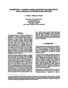
New packet arrived at t1 will be queued until t2
th
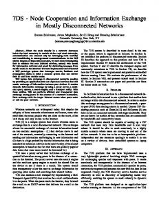
90 percentile down-link delay [ms]
300 From AP
250
From MS
Idle time
Idle time t0 t1
t2
Time Between Idle Times
200
Fig. 3.
150
Delay estimation using Time Between Idle Times (TBIT)
100
50
0 11
12
13
14
15
16
# of calls
Fig. 2. Packet delay for VoIP in IEEE 802.11b networks using DCF (G.711 CBR, 11 Mb/s)
shows some experimental results for both delay estimation and CAC decisions using TBIT. Section VI discusses the current state of the art and limitations of current approaches. Finally, Section VII concludes the paper. II. IEEE 802.11 M EDIA ACCESS C ONTROL IEEE 802.11 defines two MAC protocols, Distributed Coordination Function (DCF) and Point Coordination Function (PCF). Of these two, only DCF is widely adopted. Figure 1 shows DCF in more detail. DCF uses Carrier Sensing Multiple Access with Collision Avoidance (CSMA/CA). When a STA needs to send a packet, it senses the medium for an amount of time equal to a Distributed Inter-Frame Space (DIFS) to check if it is busy or idle. If the STA senses the medium idle, it sends the packet. If the STA senses the medium busy for DIFS or part of DIFS, it defers transmission and starts a backoff timer. The backoff timer is given by the following equation: TBO = N × T,
(1)
where T is the duration of a time slot which is PHY-layer specific and N is the number of time slots. The value of N is uniformly distributed in the interval [0, CW ) where CW is the current value of the Contention Window. CW ranges, in exponentially-increasing steps, between CWmin and CWmax . Every time the STA senses the medium idle for a duration equal to DIFS, it starts decrementing the backoff timer. If the medium becomes busy while decrementing the backoff timer, the decrementing of the backoff timer is paused. It will resume the next time the channel is idle for at least DIFS. When the backoff timer reaches zero, the STA sends the packet. If a collision occurs after sending a packet, the STA will set its backoff timer again but this time with a higher value for CW . Every time the STA experiences a collision, CW is incremented until CWmax is reached. After a successful transmission, CW is reset to CWmin .
Because of the way DCF works, the down-link delay increases sharply as soon as the number of calls exceeds the AP capacity. This exponential growth of the down-link delay is such that even accepting one single call above capacity can cause significant quality loss for all the STAs in the BSS. We have performed some simulations in ns-2, for VoIP traffic using CBR and the G.711 codec. The simulation results are plotted in Figure 2. As we can see, the down-link delay increases sharply with the number of admitted call flows. According to ITU-T [3], the one-way end-to-end delay of voice packets must be less than 150 ms. If we consider the codec delay to be about 30–40 ms at both sender and receiver and the backbone network delay to be about 20 ms, the wireless network should introduce a delay 60 ms or less. Therefore, we define AP capacity for VoIP as the maximum number of calls where the 90th percentile of up-link and downlink delay does not exceed 60 ms. In this configuration, the capacity of the AP is 14 calls (see Fig. 2) and we can see that admitting one more call above capacity increases the down-link delay to about 150 ms. This clearly shows the importance and necessity of having a good CAC algorithm in order to provide the QoS mobile users expect. III. P ROPOSAL As we mentioned in Section I, since the AP tends to be the bottleneck in IEEE 802.11 DCF networks, STAs need to know how large the load is or how long packets are delayed at the AP. However, APs do not generally provide such information, so it is necessary for STAs to estimate the AP load and packet delay by themselves in order to make CAC decisions. In this section, we introduce a method to estimate the delay in a BSS and explain how to perform CAC with it. A. Delay Estimation using Time between Idle Times In 802.11 networks, the wireless medium is shared and every STA can hear packets that other STAs and the AP send and receive. Let us consider an AP with several packets in its transmission queue. Such an AP tries to send one or more packets every time it gains access to the medium. Therefore, the AP will use any transmission opportunity it can and no idle times will be observed on the medium. Figure 3 shows an example of an AP having four packets to send at moment t0 . If we imagine that another packet arrives at t1 , the packet will have to wait until the AP empties its queue at t2 (t0 ≤ t1 < t2 ). The queuing delay for the packet is t2 −t1 and it is maximized
TABLE I AVERAGE FREQUENCY OF C ONTENTION W INDOW (CW) SIZES WITH 16 CALLS (G.711, CBR, 11 M B / S ) CW Size Frequency [%]
31 95.98
63 3.48
127 0.46
255 0.07
511 0.01
1023 0.00
when t0 = t1 . The TBIT is equal to t2 − t0 and represents a direct measure of the maximum queuing delay at the AP at the time of the observation. This makes queuing delay estimation possible by just observing TBIT. Delay estimation can be done by any STA in a BSS since every STA can “hear” the medium. Furthermore, the estimation can be performed anywhere in a BSS, even in the presence of hidden nodes. This is possible because STAs can still “hear” ACK frames sent by the AP to acknowledge packets sent by other STAs, including hidden nodes. Finally, delay estimation is done without using any additional traffic for probing the load of the AP. If the channel conditions are so poor that frames from the AP are lost, the delay estimation using TBIT might fail. In such a case, however, users would experience poor quality calls regardless of the load at the AP. Delay estimation would be a second-order issue and users should try to associate to a different AP. Delay estimation using TBIT represents a feasible way for STAs to estimate the queuing delay at their AP with low complexity. It is, in fact, important to notice that STAs already monitor the medium for idle-times during normal operations in order to apply the backoff mechanism defined in the IEEE 802.11 standard [1]. The only additional thing needed by the proposed mechanism is a simple computation of TBIT. We now explain in more detail how to estimate the queuing delay at an AP by using TBIT. As explained in Section II, every STA performs backoff after each successful transmission. This means that, even if the AP has more packets to send, it has to wait for DIFS plus TBO (see Eq. (1)). Therefore, idle periods below this duration do not indicate that the queue at the AP is empty as they do not represent a transmission opportunity. In order to take this into account, we use a threshold parameter named idle time threshold and ignore idle periods shorter than this threshold. Let Ith be the idle time threshold, we define it as: Ith = TDIF S + TSlot × CWmin ,
Usually, the value of CW increases after collisions. Table I shows the average frequency of CW sizes in IEEE 802.11b with 16 calls, that is, above the AP capacity (see Figure 2). As we can see, even when the medium is congested, CW is equal to CWmin for more than 95% of the time. As we show later in our experiments, by selecting N = CW = CWmin , Ith is big enough not to count as transmission opportunities those idle periods due to backoff, and small enough not to make our method too conservative. In IEEE 802.11b networks DIFS is 50 µs, CWmin is 31 and a slot time is 20 µs. By substituting these values in Eq. (2) we find that Ith for 802.11b networks is 670 µs. By using the idle time threshold defined in Eq. (2), a STA estimates the queuing delay by first detecting idle times, that is, idle periods longer than Ith , and then by measuring the TBIT. Since instantaneous TBIT values fluctuate, averaging techniques are used to obtain the overall trend. In this paper, we assume to use simple moving average. B. CAC using TBIT In the previous section, we showed how to estimate the queuing delay at an AP by using TBIT. This enables a STA to estimate the current delays in the wireless medium. However, in order to perform CAC, we need to know if admitting a new call causes congestion. We now show how TBIT can be used to make CAC decisions. Let us consider a STA making a new call. Let P and λ be its packet size and packet rate, respectively, and let Ttx (P ) be the time needed to send a packet whose size is P . All protocol overheads such as IFSs, backoff time, physical layer convergence protocol (PLCP), and ACK sending time are included in the calculations. Idle periods longer than Ttx (P ) can be considered as “service opportunities” for packets of the new call. Admitting a new call does not cause congestion if the frequency of service opportunities is higher than the packetrate of the new flow. Therefore, if we denote the frequency of idle times that are longer than Ttx (P ) by µ, we can say that the new call will not cause congestion if µ is larger than λ. We also notice that the frequency of idle times is obviously the inverse of time between idle times, so µ is the inverse of TBIT and is obtained in the same way as in the delay estimation. The only change we need to apply here is to set the idle time threshold as Ttx (P ), that is:
(2)
where TDIF S and TSlot are the lengths of DIFS and a timeslot duration, respectively, and CWmin is the minimum contention window size. The first term, TDIF S , is obviously the amount of idle time every station must wait before attempting a transmission. The second term is the backoff time. The backoff time is defined as in Eq. (1) where N is a random variable uniformly distributed in the interval [0, CW ). In our calculations we consider N equal to its upper bound, that is, equal to CW and we set CW to its lower bound, that is, to CW min.
Ith = Ttx (P ),
(3)
in doing so, idle periods that are not long enough to send a packet are ignored. Although Ttx (P ) is a function of P , a client which is starting a new call knows its own packet size and can calculate Ttx (P ) as follows: Ttx (P ) =
TDIF S + NSlot × TSlot + 2 × TP LCP Pack P + TSIF S + R , + Rdata ack
(4)
where NSlot is the number of time slots, TP LCP is the time needed to send the PLCP header and preamble, and TSIF S is the time duration for SIFS. Rdata and Rack are
bit-rates to send data and ACK frames, respectively, and Pack is the size of an ACK frame. Although NSlot is a random value, it is reasonably replaced by CW2min since NSlot is uniformly distributed between [0, CW ), and CW usually stays at CWmin , as we mentioned earlier. As we can see, variables other than P in Eq. (4) are static and every STA knows their values. Each STA can calculate Ttx (P ) by substituting P to Eq. (4). Consequently, a STA can obtain µ by listening to the medium. By checking whether µ is larger than λ or not, a STA can make CAC decisions by itself. C. Parameter Negotiation for CAC In order to make CAC decisions, each STA needs to know the packet rate for the new call and compute Ttx (P ). As we can see from Eq. (4), all the parameters required to calculate Ttx (P ) are known to each STA except for the packet size of the new call. Packet size and packet rate depend on the particular codec used. Because of this, in order to make CAC decisions with TBIT, each STA needs to know the codec used by the remote end-point. Let us look at this point in more detail. When a STA either wants to initiate a new call with a remote STA or has to decide whether or not to accept a new call initiated by a remote STA, it has to do CAC to make sure that the new call can be admitted without causing congestion. In order to do this with TBIT, the STA needs to know which codec it will use for the new call and which codec the remote end-point will use for such call. The remote end-point will have to do the same thing for performing CAC on its wireless link. Since TBIT is performed passively, that is, without any probing, each STA can periodically check its channel conditions and see which codecs, among the supported ones, would cause congestion. In doing so, each STA can build a white list and a black list of codecs so that codecs causing congestion are put in the black list and codecs not causing congestion are put in the white list. In particular, a STA can test multiple codecs simultaneously since it is possible to run TBIT with different idle-time thresholds at the same time. When a STA needs to make a call or respond to a call, it can choose a codec among those included in its white list. In doing so, caller and callee can negotiate which codecs to use, taking into account the load at their respective APs. One possible way to negotiate codecs is by using the Session Initiation Protocol (SIP) [4]. In SIP codecs are negotiated in the initial INVITE−200 OK handshake. In our scenario, the caller would include in the INVITE request only those codecs in its white list. On the other side, the callee would include in the 200 OK response those codecs included in the INVITE request that also belong to its white list. In selecting codecs belonging to the white list of both caller and callee, congestion is avoided. If caller and callee do not have common codecs in their white lists, the caller can cancel the call and the callee can reject it. To summarize, using SIP together with TBIT allows caller and callee to negotiate suitable codecs for both sides, thus
avoiding congestion. Furthermore, the proposed mechanism does not add any additional delay to the call setup time since each STA can keep updating its codecs’ white list during nontime-critical operations. The integration with SIP is reserved for future study. D. Misbehaving Stations STAs misbehaving to gain some kind of advantage over other STAs is a general problem that affects many protocols and standards. The IEEE 802.11e protocol is an example. In IEEE 802.11e networks four traffic classes are defined, each with its own medium access parameters. This is done so that real-time traffic such as voice, has higher priority to access the medium than, for example, data traffic. In order for this protocol to work correctly, however, STAs need to correctly classify as high-priority traffic only real-time traffic and classify as low-priority traffic best-effort traffic, for example. Nothing however, prevents rogue STAs from sending any type of traffic such as best-effort traffic, as high-priority traffic. In doing so, rogue STAs try to achieve higher throughput at the expenses of other STAs. Similarly, in IEEE 802.11 networks, rogue STAs could completely ignore the backoff procedure and try to send packets immediately, trying to achieve higher throughputs. By using TBIT each STA can make CAC decisions autonomously. Enforcement of CAC policies, however, cannot be guaranteed with a client-only approach, and rogue STAs can indeed ignore CAC rules. This said, it is important to notice that in the present context, STAs do not have any incentive to misbehave. In particular, ignoring CAC rules would degrade the communication of all STAs in the same BSS, including the rogue STA that would just experience poor network conditions. IV. E VALUATION In this section, we evaluate the performance of TBIT for delay estimation and CAC through simulations, using the ns-2 [5] network simulator. A. Simulation Setup As shown in Fig. 4, we use the Ethernet-to-wireless network topology and focus on the delay in the BSS. One AP is connected to the wired network and N STAs are in its service range. The STAs make VoIP calls with nodes over the wired network. In particular, each STA makes one VoIP call, that is, the number of VoIP calls is equal to N . One of the STAs monitors the wireless medium and computes TBIT as explained in Section III. Note that the monitoring STA can also make calls without affecting the delay estimation or CAC results. In particular, since STAs have to monitor the medium for normal operations, their monitoring of the medium can be extended to compute TBIT on top of the normal DCF operations. Since the wired portion adds 4 ms one-way propagation delay from a STA to a wired node and vice-versa, we subtract 4 ms from the end-to-end packet delay in order to focus on the delay caused by the wireless part of the network.
IEEE 802.11b
B. Evaluation of Delay Estimation using TBIT
1 Gbps, 2 ms
BSS
1 Gbps, 2 ms
Observing node
N wired VoIP nodes N wireless VoIP nodes
Fig. 4.
Simulation topology
TABLE II VO IP
CODEC PARAMETERS USED IN THE SIMULATIONS
Codec Payload Size [byte] Packetization Interval [ms]
G.711 160 20
G.723.1 20 30
Each VoIP call in the simulations is either G.711 CBR, G.711 VBR, G.723.1 CBR or G.723.1 VBR. The payload size and packetization interval of each codec are shown in Table II. VBR here means that silence suppression is used and packets are sent only during talk-spurts. The speech model we use in our simulations is ITU-T P.59 [6], which is one of the most commonly used. We did not consider any doubletalk and used 1.004 s and 1.587 s as mean values for the exponentially distributed duration of talk-spurts and silence periods, respectively. The wireless network parameters used in our simulations are set according to the IEEE 802.11b standard and are shown in Table III. Although we focus on IEEE 802.11b networks, it is important to notice that TBIT works for any CSMA/CA based MAC protocol. In particular, it works with any IEEE 802.11 standard, such as 802.11a/g/n by setting the parameters in Eqs. (2) and (4) accordingly.
TABLE III N ETWORK PARAMETERS USED IN THE SIMULATIONS (IEEE 802.11 B ) Parameter PLCP Preamble (short) PLCP Header MAC Header+CRC IP+UDP+RTP headers ACK frame size SIFS DIFS Slot Time CWmin CWmax Basic Rate Data Rate
Value 144 (72) bits 48 bits 34 bytes 40 bytes 14 bytes 10 µs 50 µs 20 µs 31 slots 1023 slots 1.0 Mb/s 11.0 Mb/s
Figures 5–8 show the simulation results for delay estimation by TBIT. In each figure, the x-axis represents the time in the simulation and the y-axis shows the packet delay. As mentioned in Section I, APs tend to be the bottleneck in IEEE 802.11 DCF networks; therefore, we show only the down-link delays. For every simulation in this subsection, the idle time threshold Ith is set to 670 µs (see Section III-A), and each estimated delay is the average of 15 TBIT samples. Let us first look at how TBIT can estimate the delay for CBR traffic, focusing on Figure 5. In this simulation a new VoIP call starts every 20 seconds until the number of calls reaches the AP capacity. The vertical lines in Figure 5 show the number of calls (second y-axis). We can see from the figure that when a new call starts, the down-link delay changes and the estimated delay changes accordingly, that is, the estimated delay follows very well the real delay. The figure also shows that when the number of calls reaches the AP capacity, the down-link delay increases significantly and the estimated delay also follows the increase. Figure 6, shows a detail of Fig. 5, that is, the transition from uncongested state to congested state. As we can see, also during the transition from uncongested state to congested state the estimated delay follows the actual delay very well. In the following we look at how well the delay estimation works for VBR traffic. Since VBR calls alternate between silence periods and talk spurts, the amount of traffic fluctuates over time and delay can increase even if the number of calls has not reached the AP capacity. Hence, we need to check if such delay fluctuations can be caught by using TBIT. Figure 7 shows some of the results for VBR traffic. We can see that TBIT works well also for VBR traffic. Until now we have shown results for VoIP-only scenarios. In real environments, however, other types of traffic are usually present and the estimation has to work with such non-VoIP traffic as well. We tested the delay estimation in a scenario where G.711 VoIP calls and background HTTP traffic coexisted. We used Packmime [7], a web traffic emulation module for ns-2, for generating the HTTP traffic. We show the delay estimation results in Figure 8. Again, we can see that the estimated delay follows the actual delay very well. As we have seen in Eq. (2), delay estimation with TBIT is independent from traffic-specific parameters such as packet size and packetization intervals. Because of this, delay estimation using TBIT does not require special tweakings according to the types of traffic present in the BSS. For example, mixed scenarios with both data and voice traffic can be handled as easily as voice-traffic only scenarios. From these results, we can say that TBIT represents a good metric to estimate the delay in IEEE 802.11 DCF networks. There are situations in which the estimated delay might seem not to follow the peaks of the actual delay. This however is due to the averaging process performed on the samples of the estimated delay. If needed, such a mismatch can be
120
25
100
80
20
60
15
40
10
20
5
0 0
50
100
150
200
250
20
60
15
40
10
20
5
0 300
0 210
215
C. Evaluation of CAC using TBIT In this section we show how TBIT can be used for CAC. We did simulations assuming both homogeneous and heterogeneous scenarios, i.e., only one kind of VoIP codec is used and different kinds of VoIP codecs are mixed together. The simulation setup is the same as in Section IV-A. 1) Homogeneous scenario: Figures 9, 10, 11, and 12 show the results of G.711 CBR, G.723.1 CBR, G.711 VBR, and G.723.1 VBR, respectively. These figures show the 90th percentile down-link delay versus the number of calls in the BSS. Each plot is a result of multiple simulations with changing random seeds. In particular, we plotted the 90th percentile delays with 95% confidence intervals. Each figure also has a second y-axis for the frequency of idle times. We define the frequency of idle times as the inverse of the average TBIT in a second and plot the average
220
0 230
225
Time [s]
Delay estimation using TBIT (G.711 CBR)
Fig. 6.
50
Delay estimation using TBIT (G.711 CBR, around capacity)
Down-link delay Estimated delay using TBIT
40 Packet delay [ms]
eliminated by using more complex average techniques and different averaging parameters. TBIT becomes less accurate during extremely high loads. When the network is highly congested, the AP always has packets to send in its transmission queue and in theory, the TBIT should be infinite. In reality, the medium will not be always busy and the TBIT will not be infinite. This is because of the backoff procedure in DCF which might cause all stations to defer transmission simultaneously for a short time, thus leaving the medium idle for some time, wasting bandwidth. In such a case, TBIT will consider such “fake” idle times as transmission opportunities, corrupting the delay estimation. In practice, however, STAs can know when these kinds of situations occur since high congestion can be detected by other means such as high packet loss rate and can respond accordingly. Furthermore, such a situation should not occur if a good CAC algorithm is used. In any event, one possible solution to this problem would be to reconfigure Ith adaptively with CW so to correct the delay estimation and ignore “fake” idle times. We plan to investigate this in the future.
25
80
Time [s]
Fig. 5.
30
Down-link delay Estimated delay using TBIT New call arrival time
# of calls
Packet delay [ms]
100
30
Packet delay [ms]
Down-link delay Estimated delay using TBIT New call arrival time
# of calls
120
30
20
10
0 550
555
560
565
570
Time [s]
Fig. 7.
Delay estimation using TBIT (G.711 VBR)
frequency of idle times. Note that the idle time threshold Ith to obtain the frequency is different for G.711 and G.723.1 codecs because they have different packet sizes. We set Ith to 780 µs for G.711 and to 680 µs for G.723.1. The time to send a packet is calculated using Eq. (4) by substituting the parameters in Table III and the packet size. Note that the short PLCP preamble is used in all the simulations and both PLCP header and preamble are sent at the basic rate of 1.0 Mb/s. With these parameters, TP LCP is 120 µs, Rack 11.0 Mb/s, Ps 234 bytes for G.711 and 94 bytes for G.723.1, including MAC header, CRC, IP, UDP and RTP headers. Figures 9–12 show how the 90th percentile delay increases with the number of calls and it exceeds 60 ms when the capacity is reached. In our simulations, the capacity was 14, 25, 32, and 58 calls for G.711 CBR, G.723.1 CBR, G.711 VBR, and G.723.1 VBR, respectively. As we have explained in Section III-B, TBIT makes CAC decisions based on whether the packet-rate of a new call exceeds the frequency of idle times. The packet-rate of a new
90 percentile down-link delay [ms]
120
Packet delay [ms]
100 80 60
th
40 20 0 200
250
200
150
150
100
100
50
50
0 205
210
215
220
0 21
22
23
24
Fig. 10.
27
28
200
200
150
150
100
100
50
50
0
0
th
250
90 percentile down-link delay [ms]
th
90 percentile down-link delay 60 ms threshold Frequency of idle times Packet rate of a new call
300
th
90 percentile down-link delay 60 ms threshold Frequency of idle times Packet rate of a new call
300
Average frequency of idle times
th
26
VoIP capacity and frequency of idle times (G.723.1 CBR)
300
250
25
# of calls
Delay estimation using TBIT (G.711 CBR with background traffic)
300 90 percentile down-link delay [ms]
250
200
Time [s]
Fig. 8.
300
th
90 percentile down-link delay 60 ms threshold Frequency of idle times Packet rate of a new call
250
250
200
200
150
150
100
100
50
50
0 11
12
13
14
15
0 27
28
29
30
31
32
33
34
35
36
# of calls
16
# of calls
Fig. 9.
Average frequency of idle times
300
Down-link delay Estimated delay using TBIT
Average frequency of idle times
140
Fig. 11.
VoIP capacity and frequency of idle times (G.711 VBR)
VoIP capacity and frequency of idle times (G.711 CBR)
utilization ratio. The utilization ratio U is defined as: call should be twice the packet-rate of each codec since each call generates two way traffic, i.e., up-link and down-link. Since the packetization intervals of G.711 and G.723.1 are 20 ms and 30 ms, respectively, the packet rates of G.711 and G.723.1 calls should be 100 packets/s and 66.7 packets/s, respectively. Therefore, if STAs make CAC decisions based on TBIT, they should not start a new call when the frequency of idle times is less than 100 for G.711 and less than 66.7 for G.723.1. Let us look at Figures 9–12. We can see for all these four scenarios that the frequency of idle times becomes less than the packet-rate of a new call just before the number of calls reaches capacity, i.e., the 90th percentile delay exceeds 60 ms. In particular, with TBIT the maximum number of accepted calls is 14, 24, 30 and 57 for G.711 CBR, G.723.1 CBR, G.711 VBR and G.723.1 VBR, respectively. In order to see how much bandwidth remains unutilized when TBIT starts rejecting new flows, we introduce the
U=
[# of accepted calls with TBIT] , [# of calls at capacity]
(5)
For G.711 CBR, G.723.1 CBR, G.711 VBR and G.723.1 VBR, U is 1.00, 0.96, 0.94, and 0.98, respectively. As we can see, TBIT makes accurate CAC decisions. From these results, we can say that CAC decisions can be taken by simply checking whether or not the frequency of idle times is larger than the packet rate of a new call. 2) heterogeneous scenarios: We now evaluate our method in scenarios where two different kinds of VoIP traffic are mixed. In one scenario we consider calls with different packet sizes and different packetization intervals. In another scenario, in addition to different packet sizes and packetization intervals, we also consider one of the two codecs to be VBR. Different Ith values are used for G.711 and G.723.1 calls. In particular, as mentioned in the previous section, we use a value of 780 µs for G.711 and 680 µs for G.723.1.
250
200
200
150
150
100
100
50
50
0
Unacceptable
0 52
53
54
55
56
57
58
59
60
61
62
63
# of calls
Fig. 12.
300 -360 240 -300 180 -240
9
120 -180 60 -120
8
0 -60 7
6
10
11
12
13
14
15
# of G.723.1 CBR calls
16
17
# of G.711 CBR calls
250
10
300
th
90 percentile down-link delay 60 ms threshold Frequency of idle times Packet rate of a new call
Average frequency of idle times
th
90 percentile down-link delay [ms]
300
5 18
Fig. 13. Contour of 90th percentile delays in ms and CAC decisions made using TBIT (G.711 CBR + G.723.1 CBR)
VoIP capacity and frequency of idle times (G.723.1 VBR)
Unacceptable
The results are shown in Figures 13 and 14. Since two kinds of calls are mixed, in order to show the different possible combinations, we use the contour of 90th percentile delays. The vertical and horizontal axes represent the numbers of G.711 and G.723.1 calls, respectively, and a coordinate (X, Y ) means that X G.711 calls and Y G.723.1 calls are active in the BSS. In the white region the 90th percentile of the delay is below 60 ms while it is higher in the other regions. Because of this, only the coordinates that are in the white region represent flows that are not causing congestion. Therefore, the line between the white region and the colored region represents the capacity line. Now, let us look at where our method tells STAs to stop in adding a new call. Each arrowed solid line in Figures 13 and 14 means that the frequency of idle times is larger than the packet rate of a G.711 call and a STA can start one G.711 call on its beginning point. Each arrowed dashed line means the same thing for G.723.1. If the tip of the arrow reaches the capacity line, it means that our method made the wrong CAC decision and accepted one too many calls, reaching congestion. As we can see from these figures, the tip of the arrows does not reach the capacity line. We can therefore say that our method also works in these heterogeneous situations. In particular, the utilization ratio, U for these cases is between 0.9 and 1.0. Also for heterogeneous VoIP traffic, TBIT makes accurate CAC decisions. We can conclude that STAs can make CAC decisions by themselves by simply checking if the frequency of idle times is larger or smaller than the packet-rate of the new call they want to start. 3) With background traffic: In the previous sections we have shown that CAC using TBIT works well for VoIP only scenarios. Now we evaluate TBIT for CAC when background data traffic and VoIP traffic co-exist. Since data is usually transmitted using TCP, the throughput of data traffic changes dynamically and it is not regulated. Moreover, TCP tries to increase the throughput until packet
19 300 -360 240 -300 180 -240 18 120 -180 60 -120 0 -60 17
16
# of G.711 VBR calls
20
15
10
11
12
13
14
# of G.723.1 CBR calls
14 15
Fig. 14. Contour of 90th percentile delays in ms and CAC decisions made using TBIT (G.711 VBR + G.723.1 CBR)
loss is detected. Because of this, even if the number of admitted VoIP calls is controlled by a CAC algorithm, background data traffic can occupy a large amount of bandwidth degrading the quality of VoIP calls. IEEE 802.11e tries to address this problem. The IEEE 802.11e standard defines an Enhanced Distributed Channel Access (EDCA) to replace DCF. In EDCA every station has four access categories (ACs) and four transmission queues, one for each of the ACs. Though EDCA has the same backoff procedure as DCF, each AC has now its own medium access parameters allowing differentiated medium access. Each AC has an independent set of CWmin , CWmax and Arbitration IFS (AIFS) which replaces DIFS used in DCF. The length of AIFS, TAIF S , is calculated as follows: TAIF S = TSIF S + NAIF S ∗ TSlot ,
(6)
where NAIF S is the number of backoff slots which is defined on a per-AC basis. The default parameters are shown in Table IV. The standard assigns VoIP traffic to AC[0] and data traffic
TABLE IV D EFAULT PARAMETER SET IN IEEE 802.11 E EDCA AC AC[0] AC[1] AC[2] AC[3]
CWmin 7 15 31 31
CWmax 15 31 1023 1023
V. I MPLEMENTATION AND E XPERIMENTS In this section we present some experimental results for delay estimation and CAC with TBIT. Due to time constraints, we focus only on G.711 CBR with background traffic. More extensive measurements are reserved for future study.
NAIF S 2 2 3 7
A. Experimental Setup 500
th
90 percentile down-link delay 60 ms threshold Frequency of idle times Packet rate of a new call
400
400
300
300
200
200
100
100
0
Average frequency of idle times
th
90 percentile down-link delay [ms]
500
0 5
6
7
8
9
10
11
12
# of calls
Fig. 15. VoIP capacity and frequency of idle times (G.711 CBR with background HTTP traffic)
to AC[3] . In doing so, VoIP traffic has higher priority than data traffic in accessing the medium, hence limiting the throughput of data traffic. We performed some simulations in ns-2 using EDCA. We considered G.711 CBR VoIP traffic and background HTTP traffic. The HTTP request rate was 5.0 [request/s] and other parameters such as the packet size, distribution of request interval and data size in each request were set to Packmime’s default values. VoIP and HTTP traffic were assigned to AC[0] and AC[3] , respectively, as in the standard. By considering a CWmin value of 7 associated with AC[0] (see Table IV) and from Eq. (4) we have that for VoIP traffic the time needed to send a packet is 540 µs. Hence, we set Ith to 540 µs in this simulation. We plotted the simulation results in Fig. 15. As we can see, the capacity in the simulations was only 10 which is less than what it was when only VoIP traffic was present (see Figure 11). The reason behind this is that now there is HTTP traffic that consumes extra bandwidth taking it away from the VoIP traffic. As we can see from the figure, the frequency of idle times becomes less than 100 when 9 calls are admitted, and TBIT stops accepting calls when 9 calls are admitted. In this case the utilization ratio, U is 0.9. Clearly, TBIT gives accurate results for CAC also when background traffic and VoIP traffic co-exist. In particular, TBIT admits a maximum number of calls that is only one call below capacity.
For our experiments we created a small wireless testbed. We used three T42 and one R51 IBM Thinkpad laptops. Each laptop ran the Linux operating system and used multiple wireless cards so that one single laptop could emulate multiple wireless clients. In particular, we used two Proxym Orinoco Gold 11a/b/g combo wireless cards, one Lucent Orinoco Gold 802.11b card, one Dlink Air Xpert 802.11abg card, one Linksys WPC11 wireless card and one Intel Pro 2200 wireless card. We also used a Lucent Wavepoint-II 802.11b AP. In order to make the experiments closer to a real scenario, throughout the experiments other wireless traffic was present at other APs, that is, our testbed was not isolated from interference. We implemented a TBIT listener to estimate the AP queuing delay and make CAC decisions using TBIT. The TBIT listener was based on Java and libpcap version 0.9.8 [8]. In particular, we used JPcap version 0.7 [9], a library and application programming interface set which enables Java applications to use libpcap. Since we used Java, our implementation works on any platform which supports Java and libpcap, for as long as the device driver is supported by libpcap. Furthermore, we implemented a simple VoIP traffic emulator in order to send and receive UDP packets at a given packet size and packet rate. Each packet sent by the VoIP emulator carried a timestamp of when it was sent so that the one-way delay could be easily computed. In the experiments, each laptop ran multiple instances of the VoIP emulator, one per each wireless interface, so that each laptop virtually worked as multiple VoIP clients. B. Implementation A straight forward approach to observe TBIT is to determine whether the medium is busy or idle and calculate the time between idle times by considering those idle periods longer than the given idle-time threshold (see Section III). Generally speaking, however, WiFi devices have medium-state information available at the lower layers, but they do not make it available at higher layers. Because of this, directly determining the status of the medium by exploiting DCF operations is currently not possible without having to modify the wireless card firmware. Device drivers, however, report other useful information at the higher layers. In particular, they can report the transmission rate and the time a packet is received by attaching an extension header on each packet, (e.g. Prism and BSD Radiotap). The TBIT listener uses such information to compute TBIT. The TBIT listener captures packets transferred on a given wireless channel, including IEEE 802.11 management and control frames such as beacons and acknowledgments; it computes what time the transmission started and ended by referring to packet size, transmission rate and time the packet was
300
th
90 percentile down-link delay 60 ms threshold Average frequency of idle times Packet rate of a new call
250
3
200
150
10
2
100
50
Average frequency of idle times
10
4
th
90 percentile down-link delay [ms] (log scale)
10
Fig. 16.
10
1
0 2
3
Fig. 17.
C. Delay Estimation Experiments We set up two laptop PCs connected to an AP via WLAN and a laptop PC connected to the AP via a wired link. One of the laptop PCs ran the TBIT listener and estimated the queuing delay. The PC connected to the AP by Ethernet sent packets with time-stamps to the TBIT listener so that the TBIT listener could plot the actual one-way delay as well as the estimated delay. The other laptop PC was used to generate background traffic so to increase the queuing delay at the AP. The clocks of all the PCs were synchronized by using the Network Time Protocol (NTP). The idle time threshold Ith was set to 670 µs and each estimated delay point has been computed as the average of 15 TBIT samples. This is the same metric we used in Section IV. The CPU load during the estimation process is sufficiently low to allow real-time delay estimation. Figure 16 is a screen shot of the plot of the delay (actual and estimated) generated by the TBIT listener taken during one of the experiments. We can see from the figure that the estimated delay follows the actual delay well. As we can see, however, there are situations in which the estimation is not as accurate. This is mostly due to our implementation of TBIT. In particular, the limitation of our current implementation is that, TBIT is computed by capturing packets. The capturing of packets is in itself a not very reliable process since packets are often missed. Furthermore, packets can also be lost due to errors and collisions. This loss in packets by the observing node
5
# of flows
Delay estimation using the Java-based TBIT listener
received; finally, it determines the idle periods and outputs the time between idle times longer than the given idle-time threshold. In order to compute and plot the one-way delay from a sender to a receiver, each VoIP client includes the time-stamp at which the packet was sent, in the packet’s payload. When the TBIT listener receives a packet of a specific format, it checks the difference between the time-stamp written in the packet and the current time, and plots the difference as oneway delay.
4
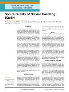
CAC using TBIT for 802.11b (G.711 CBR at 2 Mb/s)
gets translated in a lower accuracy of the estimation process. This problem can be avoided by accessing the status of the medium directly from the wireless card. Ways to solve this problem are reserved for future study. D. CAC Experiments We used four laptops and used the same topology as the one depicted in Figure 4. One laptop was connected to the AP via Ethernet to emulate a certain number of wired VoIP clients. The other three laptops had each multiple wireless interfaces so to emulate a certain number of wireless VoIP clients. The number of wireless VoIP clients was the same as the number of wired VoIP clients. The payload size and packet rate of each emulated VoIP traffic flow were 172 bytes and 50 packets per seconds, respectively, that is, it emulated a CBR G.711 codec flow. In particular, the payload size of 172 bytes included the size of RTP header and voice data. The total number of wireless interfaces used in the experiment was six. This means that the maximum number of concurrent VoIP calls in the experiment was also six. The AP was configured to set the data transmission rate in the BSS at 2 Mb/s so that six G.711 calls could reach the capacity of the wireless medium. The idle time threshold Ith was set to 1650 µs according to Eq. 4. Figure 17 shows the results for CAC. The x-axis is the number of concurrent VoIP calls and the y-axis is 90th percentile down-link delay. The figure also has a second y-axis to show the frequency of idle times and the packet rate of a call. From Figure 17, we can see that the capacity of the system was 4 VoIP calls and the frequency of idle times went below the packet rate of a new call at exactly 4 concurrent VoIP calls. As we can see, TBIT can make extremely accurate CAC decisions. In this particular scenario, TBIT stopped accepting new calls at exactly the system’s capacity. Although we have not tested every possible scenario in our testbed, these preliminary results confirm the TBIT works very well in real-time environments for delay estimation and CAC
decisions. As future work, we will deploy and test TBIT in a wider set of scenarios. VI. R ELATED W ORK A lot of research has been done for CAC in wireless networks. Many approaches however, often require changes in the either the network infrastructure, the IEEE 802.11 standard or both [10], [11], [12]. Some client-based approaches have been proposed over the years; however they usually require some probing mechanism [13] or introduce a very high cost in terms of complexity [14]. Other approaches also have been proposed for CAC in IEEE 802.11 ad-hoc networks [14], [15]. In the following we look at some of these approaches in more detail. Garg et al. [10] propose an Access Control (AC) mechanism for VoIP traffic. They calculate a Channel Utilization Estimate (CUE) by collecting data available at the AP, through a wireless gateway (WC) behind the AP. The gateway monitors the traffic to and from the AP in order to estimate the channel utilization. The CUE of a flow is defined as the amount of time the network is busy transmitting that flow. So, by summing the CUE of all flows, it is possible to determine the amount of time for which the medium is idle. A new flow can be accommodated if its CUE is smaller than the amount of idle time. Such an approach requires changes in the infrastructure and the calculation and use of the CUE for AC purposes is rather complex and requires a considerable amount of resources since all flows need to be monitored all the time and the utilization of the network needs to be correctly estimated. As explained in Section III-A, we do not calculate the utilization of the medium as this would introduce more complexity. Rather, we just measure how often an idle time, that is, a transmission opportunity occurs. Casetti et al. [11] propose a CAC algorithm to use in IEEE 802.11k and IEEE 802.11e networks. In particular, they introduce a new network element co-located within the AP and called Wireless Network Controller (WNC). Each mobile node needs to reserve radio resources for a traffic flow. The reservation request is sent to the AP which forwards it to the WNC. The WNC runs the CAC algorithm and decides if to grant the reservation or not. The reservation request contains the traffic characteristics of the new flow which are used by the WNC to estimate the current channel utilization and make a decision regarding the new flow. The way the channel utilization is calculated is rather complex and requires a large number of parameters to be taken into account. Furthermore, the channel utilization is calculated considering a maximum desired delay of 400 ms which is unacceptable for real-time media. Xiao et al. [12] propose a mechanism for protection and guarantee of voice and video traffic in IEEE 802.11e networks. In particular, a two-level protection is proposed. At the first level, the already admitted voice and video flows are protected from new flows of the same type. At the second level, already
admitted voice and video flows are protected from besteffort traffic. The first level protection is based on continuous measurements of the available bandwidth on a per-traffic-class basis; the second level protection is based on tweaking the 802.11e access parameters such as contention window and inter-frame spaces. Five different optimizations are proposed by the authors and a combination of all of them is proposed as the best approach in terms of performance. This clearly shows how this method introduces high complexity and a large number of parameters to tweak. Many of these parameters are sent by the AP to the mobile nodes, thus requiring changes in the protocol. In [13] McGovern et al. introduce a CAC algorithm based on probing. The authors propose a client-based approach where clients, before starting a new flow, probe the medium to see if the new flow can be admitted or not. The probing is done by sending ICMP packets that mimic VoIP traffic. A client that probes the medium waits for ICMP responses and based on this, it computes delay, jitter and packet loss. These parameters are then used by the client itself in deciding if to admit and start the new flow or not. Probing the medium for available bandwidth is not a novel idea and has some major drawbacks. In particular, the probing process itself can cause congestion and all ongoing calls in the BSS can suffer from it. Probing also introduces an additional delay to the call set-up delay. This additional delay, according to the authors, can be as large as 1600 ms, thus making the overall call set-up delay unacceptable from a user experience point of view. Chakeres et al. [14] propose a perceptive admission control (PAC) for IEEE 802.11 ad-hoc networks. In order to estimate the network utilization, they consider the channel busy time within a certain interval. Furthermore, 20% of the maximum bandwidth is reserved to take into account temporary fluctuations in traffic load of the already admitted flows due to mobility. Such a heuristic might lead to a significant underutilization of the medium. In the paper, only VoIP traffic is considered and no indication is given on how much bandwidth remains unutilized when the CAC algorithm starts rejecting new flows. PAC has been proposed for ad-hoc networks and it considers a busy-time ratio as CAC policy. However, the most important difference between PAC and our approach is that we consider a certain time interval as idle time, only if its duration is bigger than a certain value. This certain value is the time needed to send one packet and receive the corresponding ACK frame (see Section III-A). Any time interval shorter than such value does not really represent a transmission opportunity and therefore should not be considered as idle time. By considering the busytime ratio, the authors in [14] fail to consider such short time intervals as busy time thus losing in accuracy. In order to prove this, we conducted some simulations in ns-2 and Figure 18 shows how the busy-time ratio fails to detect congestion. As we can see, although congestion starts with flow 15 when the delay reaches 200 ms, the busy-time ratio is only around 70% leading to the false impression that new flows can still
Average down-link delay Busy-time ratio
1.0
200
0.8
150
0.6
100
0.4
50
0.2
0 1
2
3
4
5
6
7
8
Busy-time ratio
Packet delay [ms]
250
0.0 9 10 11 12 13 14 15 16 17
# of calls
Fig. 18.
Congestion detection using packet delay and busy-time ratio
be accepted. Finally, it is worthwhile noticing that one of the problems with having additional network elements such as WC or WNC is that they require a new signaling protocol with the end system. VII. C ONCLUSIONS In this paper we introduce the concept of time between idle times (TBIT) and show how this can be used to estimate queuing delay and make CAC decisions in IEEE 802.11 networks. In particular, a STA can estimate the AP queuing delay by calculating the time between idle times while following the usual DCF procedure, that is, without introducing any significant overhead. Also, CAC decisions can be made by simply checking if the frequency of idle times is larger than the packet-rate of the new call. We have confirmed with extensive simulations that TBIT represents a direct measure of the queuing delay. In particular, we show that the estimated delay follows the actual down-link delay in various traffic scenarios such as CBR and VBR VoIP, and VoIP with background data traffic. Through simulations we also show that TBIT can be used to make accurate CAC decisions for both CBR and VBR VoIP traffic, for different packet sizes and packetization intervals, in scenarios where different types of VoIP traffic are mixed and also in the presence of background traffic. In terms of performance, the utilization ratio is always between 0.9 and 1.0 for all scenarios (see Section IV-C). This clearly proves TBIT’s high accuracy in CAC decisions. TBIT is very simple and yet effective. It enables every STA in a BSS to estimate the AP queuing delay and make CAC decisions without any support from the AP and without probing the medium. TBIT also works in the presence of hidden nodes since STAs can hear the ACK frames sent to the hidden nodes by the AP. However, in the particular case in which hidden nodes exchange long frames, their transmitting period can be
mistakenly considered as an “idle time” by STAs using TBIT. We are currently investigating cooperation approaches where nodes can share statistical information regarding TBIT so that the hidden node problem can be mitigated. The main idea behind this is that the probability of multiple nodes not seeing the same node is very low. This approach is reserved for future work. Currently, we are building a test-bed in order to confirm the simulation results in a real environment. Preliminary results for G.711 CBR have proven the correctness of the simulation results showing the high accuracy TBIT can provide for delay estimation and CAC decisions. In particular, for G.711 CBR, TBIT accepts a number of flows equal to the system capacity, thus allowing the utilization of the network to its maximum. Further analysis is reserved for future work. ACKNOWLEDGMENTS This work was supported by the National Science Foundation under grants CNS 0335244 and CNS 0202063. R EFERENCES [1] IEEE Standard for Information technologyTelecommunications and information exchange between systemsLocal and metropolitan area networksSpecific requirements Part 11: Wireless LAN Medium Access Control (MAC) and Physical Layer (PHY) specifications., Institute of Electrical and Electronics Engineers (IEEE) Std., 1999. [2] S. Shin and H. Schulzrinne, “Balancing uplink and downlink delay of VoIP traffic in IEEE 802.11 WLANs using APC,” in Qshine 2006, Waterloo, Canada, August 2006. [3] “One-way transmission time,” ITU-T G.114, 2003. [4] J. Rosenberg, H. Schulzrinne, G. Camarillo, A. Johnston, J. Peterson, R. Sparks, M. Handley, and E. Schooler, “SIP: Session Initiation Protocol,” RFC 3261 (Proposed Standard), Jun. 2002, updated by RFCs 3265, 3853, 4320, 4916. [Online]. Available: http: //www.ietf.org/rfc/rfc3261.txt [5] UCB/LBNL/VINT. Network simulator ns. [Online]. Available: http: //www-mash.cs.berkeley.edu/ns/ [6] “Artificial conversational speech,” ITU-T P.59, 1993. [7] B. Labs. (2004) Web traffic generation in ns-2 with packmime-http. [Online]. Available: http://dirt.cs.unc.edu/packmime/ [8] Various. (2007) Libpcap. [Online]. Available: http://www.tcpdump.org [9] K. Fujii. (2007) Jpcap. [Online]. Available: http://netresearch.ics.uci. edu/kfujii/jpcap/doc/ [10] S. Garg and M. Kappes, “Admission control for VoIP traffic in IEEE 802.11 networks,” in IEEE Global Telecommunications Conference (GLOBECOM), December 2003, pp. 3514–3518. [11] C. Casetti, C.-F. Chiasserini, A. Conte, P. Dauchy, and M. Veglio, “A call admission control algorithm for 802.11e EDCA-enhanced WLANs,” in IEEE 62nd Vehicular Technology Conference (VTC-Fall), September 2005, pp. 2518–2521. [12] Y. Xiao, H. Li, and S. Choi, “Protection and guarantee for voice and video traffic in IEEE 802.11e wireless LANs,” in Twenty-third Annual Joint Conference of the IEEE Computer and Communications Societies (INFOCOM), March 2004, pp. 2152–2162. [13] P. McGovern, S. Chung, S. Murphy, and L. Murphy, “Endpoint admission control for VoIPoWLAN,” in 13th International Conference on Telecommunications (ICT), May 2006. [14] I. D. Chakeres and E. M. Belding-Royer, “PAC: Perceptive Admission Control for Mobile Wireless Networks,” in QSHINE ’04: Proceedings of the First International Conference on Quality of Service in Heterogeneous Wired/Wireless Networks (QSHINE’04), Washington, DC, USA, 2004, pp. 18–26. [15] Y. Yang and R. Kravets, “Contention-aware admission control for ad hoc networks,” IEEE Transactions on Mobile Computing, vol. 4, no. 4, pp. 363–377, 2005.