traditionally based their performance on achieving a high physical locality. This means ... have encouraged me during all the time I have been working on this thesis. I thank ..... Prefetching is the next logical step after caching. It uses "the .... and a network of workstations, the kind of operating systems our file system is tar-.
T
UNIVERSITAT POLITÈCNICA flPCATAUUNYA
COOPERATIVE CACHING AND PREFETCHING IN PARALLEL/DISTRIBUTED FILE SYSTEMS
Antonio Cortés Rosselló UPC. Universitat Politècnica de Catalunya Departament d'Arquitectura de Computadors Barcelona (España)
m Jesús Labarta Mancho Advisor
A THESIS SUBMITTED IN FULFILLMENT OF THE REQUIREMENTS FOR THE DEGREE Doctor en Informàtica
COOPERATIVE CACHING AND PREFETCHING IN PARALLEL/DISTRIBUTED FILE SYSTEMS
Als meus pares, Jaume i Maria Lluïsa, a la memòria del meu avi Toni que probablement s'hagués sentit molt orgullós de viure aquest moment, i molt especialment, a la Glòria, To may parents, Jaume and Maria Lluïsa, to the memory of my grandfather Toni who would have probably been very proud to live this moment, and very specially, to Glòria.
ABSTRACT
If we examine the structure of the applications that run on parallel machines, we observe that their I/O needs increase tremendously every day. These applications work with very large data sets which, in most cases, do not fit in memory and have to be kept in the disk. The input and output data files are also very large and have to be accessed very fast. These large applications also want to be able to checkpoint themselves without wasting too much time. These facts constantly increase the expectations placed on parallel and distributed file systems. Thus, these file systems have to improve their performance to avoid becoming the bottleneck in parallel/distributed environments. On the other hand, while the performance of the new processors, interconnection networks and memory increases very rapidly, no such thing happens with the disk performance. This lack of improvement is due to the mechanical parts used to build the disks. These components are slow and limit both the latency and the bandwidth of the disk. Thus, the performance of the file-system operations that have to access the disk is also limited. As the mechanical technology cannot keep the pace of the electronic one, the research community is in search of solutions that improve the file-system performance without expecting a significant improvement in the mechanical devices. In this thesis, we propose a solution to this problem by decoupling the performance of the file system from the performance of the disk. We achieve it by designing a new cooperative cache and some aggressive-prefetching algorithms. Both mechanisms, decrease the number of times the file system has to access the slow disk in the critical path of the user request. Furthermore, the resources used in these solutions are large memories and high-speed interconnection networks which grow at a similar pace as the rest of the components in a parallel machine.
vu
viii
COOPERATIVE CACHING AND PREFETCHING
We propose a new approach to design cooperative caches. This kind of caches have traditionally based their performance on achieving a high physical locality. This means that the system tried to cache file blocks in the nodes were they were going to be used. Our thesis is that high-performance cooperative caches can be implemented without exploiting this locality. We will prove that focusing the design on the global effectiveness of the cache, the speed of remote operations and the simplification of the coherence mechanism ends up in a better and simpler cooperative cache. We also propose a mechanism that converts traditional prefetching algorithms in aggressive ones that take advantage of the large sizes of the cooperative cache. In this work, we have designed two cooperative caches using the proposed new approach. The first one has a centralized control and its main objective was to increase our knowledge about cooperative caches. With this design, we also wanted to prove that a centralized control is not a bad idea for small networks with tenths of nodes. The second design is a distributed one and also includes a fault tolerance mechanism. In this second design, we prove that the new approach proposed in this thesis really achieves high-performance cooperative caches. All the results presented in this thesis have been obtained through simulations so that a wide range of architectures can be studied. Furthermore, we have also used a new simulation methodology that allows more accurate simulations than the traditional one. To test this work, we have compared our proposals with the state of the art in cooperative caches and parallel/distributed file systems. These comparison has be done under two environment. The first one characterizes a parallel machine and the workload used in the one described in the CHARISMA project. The second one emulates a network of workstations using the Sprite trace files.
ACKNOWLEDGMENTS
I would like to thank Jesús Labarta, my thesis advisor, for his guidance of this dissertation and his support. He has taught me all I know about researching and his patience with me has been infinite (unfortunately, not like his free time). I am specially grateful to Sergi Girona for many insightful discussions in the first stage of this work. I also want to thank him for his patience reading my manuscripts and making interesting comments which I did not always follow. Finally, I am in debt with him for all the modifications, and new features implemented in DIMEMAS without which this work could have never been done. My gratitude also to Maite Ortega for her encouragement throughout all the time I have been working on this thesis. I also want to thank her for implementing the first prototype of the cooperative cache described in this work. Among all the teachers I've had during my academic life, I am in debt with Nacho Navarro, Jordi Torres and Teo Jové because they were the first ones to show me what an operating system was. Since then, operating systems have become one of my greatest interests. Furthermore, I also have to thank Nacho Navarro for guiding my first steps in the task of researching. I have a tendency to get very excited with a successful result and to get very upset when the results are not as successful. Roger Espasa lias been the person who has always tried to balance my mood so that bad moments are not so bad. I thank him for this, although I am not sure about his success. I also thank him for being an excellent office-mate during these five years and for helping me every time I needed a counsel.
IX
x
COOPERATIVE CACHING AND PREFETCHING
I also want to thank the system administrators from both LCAC and CEPBA and specially to Oriol Riu, Judit Jiménez and Rosa Castro for their excellent technical support. I also want to thank all of them for those wonderful and relaxing coffee breaks and for our weekly lunches. There have been two very special friends, Manuel Torralaba and Jeny Panades, that have encouraged me during all the time I have been working on this thesis. I thank Manuel for all the exciting and very useful discussions we have had in the last years. I also thank him for all the wonderful moments we have shared together. To Jeny, I have to thank her for being such a good friend and for always being ready to listen to me (by the way, did I ever tell you what this thesis is about?). I would like to thank my parents, Jaume and Maria Lluïsa, and my brother Kikus for their love and support along these years. Their dedication and encouragement has made possible this work. I also thank them for believing that I was going to finish this work more than I did at some times. There is a person which has suffered the worst part of working on a thesis: bad moods, no free time, etc. Gòria has bared all of these without complaining (or at least, not too often). Furthermore, she has given me all the support I needed in all those bad moments when you really need somebody. For all of this, and for many other things I have no space to write down here, thanks a lot. Finally, I'd like to tank Xavi Martorell and Yolanda Becerra for reading this document and making many interesting comments.
This work was supported in part by the Ministry of Education of Spain under con tracts TIC 537/94 and TIC 0429/95 by the CEPBA (European Center for Parallelism of Barcelona).
CONTENTS
LIST OF FIGURES
xvii
LIST OF TABLES
xxii
1
2
INTRODUCTION
1
1.1 Motivation
1
1.2 Scope of this Work
4
1.3 Objectives
7
1.4 Work Structure
8
PARALLEL/DISTRIBUTED FILE SYSTEMS
11
2.1 Introduction
11
2.2 Parallel Machines vs. Networks of Workstations
12
2.3 Operating System
14
2.4 Interface: State of the Art
16
2.4.1 Conventional Interface
16
2.4.2 Shared File Pointers
17
2.4.3 Data Distribution
18
2.4.4 Collective I/O
-
22
2.4.5 Interfaces aimed at Multidimensional Arrays 2.5 Cache: State of the Art
23 24
2.5.1 Replacement Policies
24
2.5.2 Delayed Write
26
2.5.3 Application-Directed Caches
26
xi
xii
COOPERATIVE CACHING AND PREFETCHING
2.5.4 Virtual Memory vs. File-System Cache
27
2.5.5 Multi-level Caching
27
2.5.6 Cooperative Caches
28
2.5.7 Cache Coherence
29
2.5.8 Non-Volatile RAM
31
2.6 Prefetching: State of the Art
31
2.6.1 User-Directed Prefetching
31
2.6.2 Prefetching via Data Compression
32
2.6.3 Aggressive Prefetching Based on File Openings
32
2.6.4 Parallel Prefetching
33
2.7 Disk: State of the Art
3
33
2.7.1 Disk-allocation Policies
34
2.7.2 Log-Structured File Systems
34
2.7.3 Striping Data Among Several Disks
36
2.7.4 A Hierarchy of Disks
37
2.7.5 Using Flash Memory instead of Disks
38
2.7.6 Striping and Log-Structured File System
39
METHODOLOGY
41
3.1 Simulator (DIMEMAS)
41
3.1.1 Architectural Model
42
3.1.2 Process Model
43
3.1.3 Communication Model
43
3.1.4 Disk Model
44
3.1.5 Process-Scheduling Policies
45
3.1.6 Trace-file Format
46
3.2 Simulation-Methodology Issues
47
3.3 Workload Characterization
50
3.3.1 Parallel Workload (CHARISMA)
50
3.3.2 Network of Workstation Workload (Sprite)
53
Contents
xiii
3.4 Parallel Environment Characterizations
55
COOPERATIVE CACHING AND CENTRALIZED CONTROL
57
4.1 Motivation
57
4.2 File-System Architecture
59
4.3 Block-Distribution and Replacement Algorithms
61
4.3.1 Design Issues
61
4.3.2 Block Distribution Algorithm
62
4.3.3 Replacement Algorithm
62
4.4 Coherence Mechanism
63
4.5 Adaptability to the Variation of Nodes and Virtual Memory
64
4.6 Experimental Results
66
4.6.1 Algorithm Comparison
67
4.6.2 Interconnection Network Bandwidth Influence
70
4.6.3 "Local-Cache" Size influence
71
4.6.4 Number of Links Influence
73
4.6.5 Single Server Performance
74
4.7 Conclusions
75
COOPERATIVE CACHING AND DISTRIBUTED CONTROL
77
5.1 Motivation
77
5.2 File-System Architecture
78
5.3 Block Distribution and Replacement Algorithm
80
5.4 Coherence Mechanism
83
5.5 Buffer Redistribution
83
5.6 Adaptability to the Variation of Servers, Nodes and Virtual Memory
86
5.7 Tuning PAFS
87
5.7.1 Queue-tip Size
88
5.7.2 Redistribution Interval
89
5.7.3 Limiting the Number of the Buffers that can be Lost
90
5.7.4 Redistribution Algorithms
91
xiv
COOPERATIVE CACHING AND PREFETCHING
5.8 Experimental Results 5.8.1 Algorithm Comparison
92
5.8.2 Interconnection Network Influence
98
5.8.3 "Local-Cache" Size Influence
6
7
100
5.9 Conclusions
102
FAULT TOLERANCE
103
6.1 Motivation
103
6.2 Parity Mechanism
104
6.3 Tolerance Levels
106
6.4 Experimental Results
109
6.5 Conclusions
111
LINE AR-AGGRESSIVE PREFETCHING
113
7.1 Motivation
113
7.2 Prefetching Algorithms
114
7.2.1 One-Block-Ahead (OBA)
114
7.2.2 Interval-and-Size-Graph (ISG)
115
7.3 Linear-aggressive Prefetching
8
92
122
7.3.1 Aggressive One-Block-Ahead (Agr_OBA)
122
7.3.2 Aggressive Interval-and-Size-Graph (AgrJSG)
122
7.3.3 Limiting the Aggressiveness: Linear-aggressive Prefetching
123
7.4 Including the Linear-aggressive Algorithms in PAFS and xFS
124
7.5 Experimental Results
125
7.5.1 Performance Improvement
126
7.5.2 Disk Traffic
130
7.6 Conclusions
134
CONCLUSIONS AND FUTURE WORK
135
8.1 Contributions of this Work
135
8.1.1 Cooperative Caching
136
Contents
A
xv
8.1.2 Prefetching
138
8.1.3 Methodology
139
8.2 Future Work
140
xFS AND N-CHANCE FORWARDING
143
A.I Introduction
143
A.2 N-Chance Forwarding: a Cooperative Cache
144
A.3 xFS: General Overview
145
A.4 Comparison between Cooperative-cache Algorithms
148
A.5 Modifications Made in our Simulations
149
REFERENCES
151
xvi
COOPERATIVE CACHING AND PREFETCHING
LIST OF FIGURES
Chapter 1 1.1 Parts of a parallel/distributed file system.
5
Chapter 2 2.1 A nested-strided operation with two levels of strides.
19
2.2 Schematic representation of a two-dimensional file in Vesta.
20
2.3 An Example of data partitioning in MPI-IO.
21
2.4
25
Flow diagram of blocks in a segmented-LRU cache.
2.5 Differences between a traditional Unix file system and a log-structured file system.
35
2.6
39
Striping based on log-structured file systems as used in Zebra.
Chapter 3 3.1 Example of a parallel machine modeled by DIMEMAS.
42
3.2 Distribution of read and write operations on CHARISMA
51
3.3 Distribution of read and written MBytes on CHARISMA
52
3.4 Distribution of read and write operations during the simulation on the Sprite workload.
54
3.5 Distribution of read and written MBytes during the simulation on the Sprite workload.
54
Chapter 4 4.1 File-system architecture of the centralized version, xvii
60
xviii
COOPERATIVE CACHING AND PREFETCHING
4.2
Approximation of the LRU-Interleaved to a global LRU.
63
4.3
Normalized time spent by the centralized version of both file systems serving read and write operations.
68
Influence of the interconnection-network bandwidth on the centralized version of PACA and xFS.
71
Influence of the "local-cache" size on the centralized version of PACA and xFS.
72
4.6 Influence of the number of links to the interconnection network on the centralized version of PACA and xFS.
74
4.4 4.5
Chapter 5 5.1
PAFS architecture.
79
5.2 An example of two cache-server partitions in a three-node machine.
79
5.3 Influence of the queue-tip size on the local-hit ratio (PM/CHARISM A).
89
5.4 Influence of the queue-tip size on the local-hit ratio (NOW/Sprite).
89
5.5 Influence of the interval between redistributions (PM/CH ARISM A).
90
5.6 Influence of the interval between redistributions (NOW/Sprite).
90
5.7
Influence of the limitation of lost buffers (PM/CHARISMA).
91
5.8
Influence of the limitation of lost buffers (NOW/Sprite).
91
5.9
Influence of the limitation of gained buffers (PM/CHARISMA).
92
5.10 Influence of the limitation of gained buffers (NOW/Sprite).
92
5.11 Total normalized time spent by PAFS and xFS performing read and write operations (PM/CHARISMA).
93
5.12 Total normalized time spent by PAFS and xFS performing read and write operations (NOW/Sprite).
93
5.13 Interconnection-network bandwidth influence in the average read and write operation times (PM/CHARISMA).
98
5.14 Interconnection-network bandwidth influence in the average read and write operation times (NOW/Sprite).
98
5.15 "Local-cache" size influence in the average read and write operation times (PM/CHARISMA).
100
List of Figures
5.16 "Local-cache" size influence in the average read and write operation times (NOW/Sprite).
xix
100
Chapter 6 6.1
Distribution of the cache buffers in parity lines.
105
6.2 Example of a parallel make that needs a high tolerance level
108
6.3 Performance of the fault-tolerance levels (PM/CHARISMA).
109
6.4 Performance of the fault-tolerance levels (NOW/Sprite).
Ill
Chapter 7 7.1 Example of a couple of access patters and their prefetch graphs.
116
7.2
118
Example of a graph creation.
7.3 Example of a prefetch graph where nodes have more than one link that start from it.
119
7.4 Example of a regular access pattern that cannot be prefetched by ISG.
121
7.5 Average read operation time obtained by the presented prefetching algorithms on PAFS (PM/CHARISMA).
126
7.6 Average read operation time obtained by the presented prefetching algorithms on xFS (PM/CHARISMA).
126
7.7 Average read operation time obtained by the presented prefetching algorithms on PAFS (NOW/Sprite).
129
7.8 Average read operation time obtained by the presented prefetching algorithms on xFS (NOW/Sprite).
129
7.9 Load placed on the disks by ISG with a 1 MByte local cache.
132
Chapter 8 Appendix A A.I Possible xFS configuration in a network of workstations.
146
A.2 Steps followed by xFS to fulfill a client request.
147
xx
COOPERATIVE CACHING AND PREFETCHING
LIST OF TABLES
Chapter 1 1.1 Summary of hardware improvement trends,
2
Chapter 2 2.1 Interconnection-network and memory bandwidth of some parallel machines (peak values).
12
2.2 Peak bandwidth of the most popular interconnection networks used in NOWs. -
12
2.3 Sustainable memory bandwidth of some popular workstations.
13
Chapter 3 3.1 Some of the actions that can be represented in a DIMEMAS trace 3.2
file.
CHARISMA workload
46 51
3.3 Sprite workload
53
3.4 Simulation parameters.
56
Chapter 4 4.1 Average operation times and hit ratios obtained using the centralized versions of PACA and xFS. '
67
4.2 Influence of the "local-cache" size on the read global-hit ratio using the centralized version of PACA and xFS.
71
Chapter 5 xxi
xxii
COOPERATIVE CACHING AND PREFETCHING
5.1 Average read/write times and hit ratios obtained by both file systems (PM/CHARISMA).
93
5.2 Average read/write times and hit ratios obtained by both file systems (NOW/Sprite).
97
5.3 "Local-cache" size influence on the read global-hit (PM/CHARISMA) ratio.
101
Chapter 6
Chapter 7 7.1 Global miss ratio obtained by the presented prefetching algorithms (PM/CHARISMA).
127
7.2 Global miss ratio obtained by the presented prefetching algorithms (NOW/Sprite).
129
7.3 Variation in disk traffic due to the presented prefetching algorithms (PM/CHARISMA).
130
7.4 Average number of times a block is sent tot he disk during its life in the cache.
131
7.5 Variation in disk traffic due to the presented prefetching algorithms (NOW/Sprite).
133
Chapter 8
Appendix A
l INTRODUCTION
1.1
MOTIVATION
When examining the structure of the applications that run on parallel machines, we observe that their I/O needs increase tremendously every day. These applications work with very large data sets which, in most cases, do not fit in memory and have to be kept in disk. The input and output data files are also very large and have to be accessed very fast. These large applications also want to be able to checkpoint themselves without wasting too much time. These facts constantly increase the expectations placed on parallel and distributed file systems. Thus, these file systems have to improve their performance to avoid becoming the bottleneck in parallel/distributed environments. On the other hand, while the performance of the new processors, interconnection networks and memory increase very rapidly, no such thing happens with the disk performance (Table 1.1) [Dah95]. This lack of improvement is due to the mechanical parts 1
CHAPTER 1
Hardware Parameter Disk latency Disk bandwidth Disk cost/capacity Network latency Network bandwidth Memory bandwidth Memory cost/capacity Table 1.1
Improvement Rate 10% per year 20% per year 100% per year 20% per year 45% per year 40% per year 45% per year
Summary of hardware improvement trends.
used to build the disks. Operations such as the movement of the heads and the rotation of the disks are handled by mechanical components. These components are slow and limit both the latency and the bandwidth of the disk. Thus, the performance of the file-system operations that have to access the disk is also limited. As the mechanical technology cannot keep the pace of the electronic one, the research community is in search of solutions that improve the file-system performance without expecting a significant improvement in the mechanical devices. Many solutions have been proposed either to increase the disk performance or to decouple the file-system performance from that of the disks. Most of these solutions will be described in detail in the state of the art sections from Chapter 2. Among all of them, we are specially interested on caching and prefetching. A cache, or buffer cache, is a mechanism that tries to minimize the number of times the file system has to access the disks. This decouples the performance of the file system from the performance of the disks. The basic idea consists of keeping the file blocks used by the applications in memory buffers. If applications have temporary locality, the same set of file blocks is used during a certain amount of time. In this case, these requested blocks do not need to be fetched from the disk as they are already kept in the cache. This increases the performance of read operations. The cache also increases the performance of write operations as the modified blocks are not sent to the disk but kept in the cache. Whenever the system believes appropriate, it sends these modified
Introduction
blocks to the disk. One of the most attractive characteristics of this approach is that the effectiveness of a cache is not fully limited by the mechanical parts of the disks and thus its efficiency can keep the pace of the rest of the parallel machine. Prefetching is the next logical step after caching. It uses "the same data structures and mechanisms but instead of remembering blocks requested in the past it tries to predict the blocks that will be requested in the near future. So far, a cache only keeps the blocks already used by the applications. If we add a predictor, the system can also predict the blocks that will be needed by the applications and fetch them from disk before being requested. This increases the system performance if the prefetched blocks have been correctly predicted and on the right time. This mechanism also helps to decouple the performance of the file system from the performance of the disks. If we examine the trends in technology, we can observe that memory is becoming cheaper every year. For this reason, the amount of MBytes that can be placed in each node of a parallel'machine also increases very rapidly. A portion of these large memories can be used to improve the file-system performance if used as file-system caches. The larger the cache is, the more effective the caching will be. A second trend in technology that can be used to improve the I/O performance is the increasing interconnection-network bandwidth. Accessing the information kept in another node of the parallel machine is becoming less and less time consuming. This leads to believe that data needed by a given node can be kept in a different node. This information can be requested from the remote node whenever necessary. This can only be done if this remote access is fast enough, as occurs in most parallel machines. Furthermore, it is becoming a general trend in the design of parallel machines to add special hardware that copies blocks of memory between nodes offering very high bandwidths [Gil96, Gra96]. This could be used to increase the size of the file-system caches. The system could use a part of the memory in each node to build a very large global file-system cache. This would increase the effectiveness of the cache and the efficiency of the file system.
CHAPTER 1
Both ideas, large caches and high interconnection network bandwidths, are used to build what it is commonly know as cooperative caching. The idea is very simple. All nodes dedicate a portion of their large private memory to build a large global cache [DWAP94, Dah95]. The way this large cooperative cache is handled is what makes the difference between all the proposed cooperative caches. In this thesis, we are going to propose a novel approach to design and manage cooperative caches. The efficiency of these kind of caches has been traditionally based on a high physical locality. This means that the system tries to cache the data in the node that will need it. After a deep study of the implication this design issue may have, we have detected that this approach has the problem that achieving this locality has a quite high overhead on remote operations. We propose a new approach were the efficiency of this kind of caches is not based on this locality. We will prove that very efficient cooperative caches can be designed focusing on two basic issues: increasing the global effectiveness of the cache and performing local and remote accesses in the fastest possible way. Locality will only be taken into account if achieving it does not add any overhead to the system. Furthermore, we are also going to propose a mechanism that uses these large caches to implement aggressive prefetching. This prefetching will be aggressive enough to increase the system performance but will also be intelligent enough not to flood the cache. If the cache is flooded, the performance of the system drops and no benefit is obtained due to the prefetching. These two mechanisms, cooperative cache and aggressive prefetching, will increase the file-system performance using hardware that grows at a similar pace that the whole parallel-machine performance.
1.2
SCOPE OF THIS WORK
This thesis is focused on designing a new cooperative cache using a novel approach. We will redesign the full cache from scratch and we will test its performance comparing
Introduction
Cache coherence Local caches
I
Global cache
c/î
a
8 § •
Prefetch fault tolerance
g o 0)
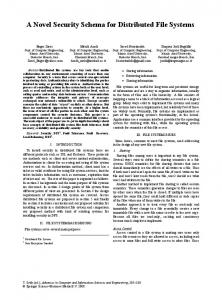
Fault tolerance Disk organization
Figure 1.1 Parts of a parallel/distributed file system.
it to the state of the art in cooperative caches. We also want to present prefetching mechanisms that are able to take advantage of the characteristics offered by the cooperative caches. This new design implies a redesign of some other parts of the parallel/distributed file system. Figure 1.1 presents all the parts that make a file system. It also shows which parts have to be modified along with the cooperative cache (light shaded). In this section, we will justify the decision of which parts need to be modified and which ones do not. In a cooperative cache, the cache can be divided in two parts: a local and a global one. Each node has a local cache and manages it so that the blocks most needed by the applications running on this node are kept in this local cache. The global cache has a more general mission, it keeps file blocks that are important for the whole system, not favoring any given node or application. As the different parts of the cache are managed in a distributed way, it is quite frequent to find replicated information in the system. This replication is allowed because it is assumed to increase the system performance. Having blocks replicated in several nodes means that modifying one of these copies leaves the system inconsistent. Not all the buffers that keep the same block have the same information. The way this problem is handled depends on the way the cooperative cache is designed and the sharing semantic implemented in the system. For this reason, redesigning a cooperative cache implies a redesign of the coherence mechanism.
CHAPTER 1
One of the basic ideas of a cooperative cache is that file blocks may be cached in any node. This means that when an application modifies a file block, this block can be placed in any node of the machine. This modified block may even be placed in a node where the applications is not running. If this node fails, the modified block will be lost and the application will be affected by the failure of a node that has nothing to do with the application. This is not acceptable in some environments and a tolerance mechanism should appear in our design. For this reason, we also have to design a fault-tolerance mechanism to solve this important problem. The other parts of a file system fall out of the scope of this thesis as a new design is not needed nor specially beneficial to the new design proposed. In the remaining of this section, we will describe the assumptions made on the unmodified parts of the parallel/distributed file system. The interface assumed is the one offered by any Unix system. This does not mean that any other more sophisticated interface can not be used, it only means that our cache will not rely on any special information given by a non Unix interface. Anyway, it seems reasonable to study how could our cache benefit from interfaces that allow the user to specify more semantic information about their operations, but this study falls out of the scope of this work. As far as security is concerned, our system will have the same security issues as a centralized system. All possible problems derived from the network and remote nodes are not taken into account. We assume a secure network. We also assume that all nodes in the network are secure. This should not be a very important limitation as the system is designed to run in a parallel machine where nodes and communication are secure. Running this system in a network of workstations should not be a big problem either as they are usually protected from the outside by sophisticated mechanisms such as firewalls. Anyway, it also seems interesting to study a way to increase the system security in the near future. The disk organization is also out of the scope of this work. Any state of the art algorithm could have been used as the behavior of the cache does not depend much on
Introduction
this organization. We have assumed an interleaved placement of blocks among disks and a file system structure based on i-nodes. This structure was used because it is very well-known and it should help us, and the reader, to interpret the results presented later in this work.
1.3
OBJECTIVES
In this section, we present, in a very schematic way, the main objectives of this thesis. These objectives will be pursued through out all this work although they may be relaxed a little bit in some chapters.
Design a cooperative cache for a parallel/distributed file system. This new design will be used to prove that a high-performance cooperative cache can be designed using the following design issues: — Favor global effectiveness over physical locality. — Favor the efficiency of remote operations over physical locality. — Offer a very strict sharing semantic ( Unix-like) by not allowing data replication. This will eliminate the coherence problem and will also simplify significantly the file-system design. Offer a simple and efficient fault-tolerance mechanism that avoids losing any modified data when a node fails. Design prefetching mechanisms that take advantage of the large size of a cooperative cache. — It has to be aggressive to use'the large caches. — It should not flood the cache with useless data.
CHAPTER 1
1.4
WORK STRUCTURE
This thesis is organized in 8 chapters as follows:
•
Chapter 2 gives a general overview of the target environment of this work. We present the kind of machine, operating system and general assumptions used in this work. We also present the state of the art in the file system field.
•
Chapter 3 starts describing DIMEMAS, the simulator used to obtain all the performance results. Then, we go through the methodology used in the simulation. And finally, we describe the simulated workloads and the parameters used in the simulator.
•
Chapter 4 presents the first proposal of our cooperative cache. This is a centralized version which is basically used to get a deep understanding on the way cooperative caches work. Furthermore, it also serves to obtain the first feedback of the viability of the novel approach proposed in this thesis.
•
Chapter 5 describes the distributed version of the cooperative cache. In this chapter, we present the final version of the file system and cooperative cache designed following the approach proposed in this thesis. We also present and evaluate some alternatives to the basic design but always keeping in mind the main structure proposed in this thesis.
«
Chapter 6 modifies the proposed file-system architecture in order to offer some degree of fault tolerance. Furthermore, three tolerance levels are proposed so that the most adequate can be used in each system.
•
Chapter 7 describes the linear-aggressive prefetching. This is a mechanism that converts a conservative algorithm in an aggressive one. These new prefetching algorithms are aggressive enough to highly increase the file-system performance. But they are intelligent enough not to flood the cache and decrease the overall system performance.
•
Finally, Chapter 8 presents the most important conclusions extracted from this work. It also gives a brief description of the work that could follow and complement the one presented here.
Introduction
In Chapters 4, 5, 6 and 7, the performance results presented have been compared against the ones obtained by xFS, the distributed file system proposed in the NOW project [ACPtNt95, ADN+95, Dah95].
10
CHAPTER 1
2 PARALLEL/DISTRIBUTED FILE SYSTEMS
2.1
INTRODUCTION
In this chapter, we will set the basis for this work. We will first describe the environment in which this work is designed to run, the differences between a parallel machine and a network of workstations, the kind of operating systems our file system is targeted at and the most important abstractions needed from the operating system in order to implement our file system. Finally, we will examine the state of the art in parallel/distributed file systems. This state of the art will be divided into four parts: interface, cache, prefetching and disk.
11
CHAPTER 2
12
Parallel machine
Network bandwidth (per link)
Memory bandwidth
0.4 GBytes/s 0.5 GBytes/s
0.8 GBytes/s
Silicon Origin 2000 Cray T3E Tera MTA NEC SX-4 (IXS)
2.67 GBytes/s 8 GBytes/s
1.2 GBytes/s 2.67 GBytes/s 16 GBytes/s
Table 2.1 Interconnection-network and memory bandwidth of some parallel machines (peak values).
Network Name Ethernet Fast Ethernet
1.25 MBytes/s 12.5 MBytes/s
FDDI
12.5 MBytes/s
ATM
78 MBytes/s 100 MBytes/s 168 MBytes/s
Memory Channel Myrinet Dolphin Table 2.2 NOWs.
2.2
Network bandwidth
200 MBytes/s
Peak bandwidth of the most popular interconnection networks used in
PARALLEL MACHINES VS. NETWORKS OF WORKSTATIONS
The cooperative cache presented in this work is designed to run in a parallel/distributed environment. This can either be a parallel machine or a network of workstations and it is important to clarify the differences between both environments. In this section, the most basic differences are explained. In both environments, we have a set of nodes connected through an interconnection network. One of the most important differences appears in this network as the one found in a parallel machine is usually much faster than the one found in a network of workstations. For this reason, the services implemented on a parallel machine can rely
Parallel/Distributed File Systems
13
Processor
Memory bandwidth
HP C180
262 MBytes/s
DEC 4100 5-300E Pentium based Sun Ultra2 2200 SGI Octane 195 IBM R6000 591
261 MBytes/s (around) 128 MBytes/s 311 MBytes/s 351 MBytes/s 800 MBytes/s
Table 2.3 Sustainable memory bandwidth of some popular workstations. values have been extracted from the STREAM Benchmarks.
These
on communication much more than if they were running on a network of workstations. This difference in the interconnection-network bandwidth can be observed comparing tables 2.1 and 2.2. We can also observe that in most parallel machines, the memory bandwidth is around twice the bandwidth of the interconnection network (Table 2.1). Furthermore, this same ratio, can also be obtained in a network of workstations if the appropriate network is used (Tables 2.2 and 2.3). The second difference can be found in the concept of node. In a parallel machine, all nodes are more or less equal and belong to no particular user. The system administrator is the only responsible for all the nodes and the nodes are not especially configured to meet the special needs of a given user. On the other hand, in a network of workstations each workstation may belong to a different user who can configure it in any way he or she wishes. This concept of ownership, that only exists in the network of workstations, is the cause of the following differences. As each workstation belongs to a given user, this user may decide that the node will not cooperate on the network tasks during a certain period of time. This can be done to increase the node performance when the user needs to do a lot of computational work. This will not happen in a parallel machine as nodes are not supposed to work for any special user. For this reason, allowing temporal disconnections is a must in a network of workstations while it may not be necessary in a parallel machine.
14
CHAPTER 2
Finally, there is the problem of fault tolerance. In most parallel machines, but not all, the failure of a node means the failure of the whole machine. If this is the case, there is no need to add fault tolerance mechanisms to the services running on top. On the other hand, in a network of workstations, the failure of a single node may be quite frequent. It is quite common for a given user to decide to shut the workstation down and this cannot mean the failure of the whole network. For this reason, all services running on a network of workstations should be able to handle node failures. Once we have clarified the difference between parallel machines and networks of workstations, it is important to say that the work presented here was originally designed to work on a parallel machine. Anyway, as networks of workstations are becoming very popular and are starting to compete with parallel machines, some modifications to the original design have been done to be able to run our system in a network of workstations.
2.3
OPERATING SYSTEM
The philosophy of our file system is that responsibilities are distributed among the nodes in the network. We want to have several nodes in charge of coordinating the contents of the cache and serving the client requests. We also want other nodes to be responsible for the disks. These nodes will have the disks connected to them and will perform all physical read and write operations. Another set of nodes will also be responsible for maintaining the information needed to have a fault-tolerant system. In this way, all file-system responsibilities are distributed among the nodes in the network. This does not mean that a given node may not have more than one responsibility, but a good distribution of tasks is desirable. This distribution of tasks can be done in two different ways. The first one consists of implementing a set of servers that take care of each part of the file system. In this case, the personality of each node depends on which server, or servers, are running on it. The other way to make this distribution consists of modifying the kernel to manage a certain part of the file system. We have decided to use the first approach as it is
Parallel/Distributed File Systems
15
simpler to implement. Furthermore, in the experimental part of this work we have seen that it does not introduce a significant overhead. Another important aspect of this work, is the assumptions we make about the operating system our file system is designed to run on. These assumptions are described in detail in the following paragraphs. The first assumption is that the operating system is a multi-programmed and multithreaded one. This is needed for a couple of reasons. The first one is to be able to run servers and clients in the same node sharing the CPU. Furthermore, it would be quite interesting to be* able to have multi-threaded servers in order to have several requests handled in parallel. Second, we need ports to communicate the clients with the servers. This mechanism will only be used to send requests from the client to the server and to send notifications from the server to the clients. No file data will be send using this mechanism. Finally, a memory-copy mechanism is needed. This mechanism is used to transfer data between the cache and the user. This mechanism should be faster than sending the information through a port. Our assumption is that any processor can set up a data transfer between any other two processors. Similar remote-memory-access mechanisms are supported in a variety of distributed-memory systems [LGP+92, WMR+94]. Operations such as memory-copy have to be supported by the hardware. We need a fast hardware mechanism to copy memory blocks from one node to another. This kind of fast copies are being implemented in most currently designed parallel machines [Gil96, Gra96]. For this reason, we believe that assuming a fast remote-memory copy operation is a reasonable assumption as it is a trend in the design of new parallel architectures. Through out all this work we have assumed that the file system is built on top of a micro-kernel operating system. We have chosen this operating-system architecture instead of a monolithic one as it seems to be best fitted for a parallel machine and to
16
CHAPTER 2
support subsystems made by servers. Anyway, a monolithic operating system could have also been used.
2.4
INTERFACE: STATE OF THE ART
In the last years, many research groups have been working on different I/O interfaces. Some of them are quite conservative and only present small modifications over the traditional one found in Unix. Others, which try to be more innovative, propose completely new semantics. These new semantics are designed to allow users to specify the nature of their applications much more precisely. All these projects have been developed basically following two different approaches. The first one consists of integrating the new semantics into the file system itself. The second one is to build a run-time library in order to offer the new semantics to the user. These libraries use the old semantics built in the file system underneath in order to offer the new ones to the user. The first option achieves a better integration with the file system , thus achieving a higher performance. The second option is much more flexible and portable as it is not chained to a specific file system. In this work, we will not take into account this difference as all the semantics proposed could have been implemented using any of the two techniques, without losing any of their basic properties. In the following subsections, we will briefly describe these projects and the new concepts they have proposed. We will start describing the conventional interface which was designed in the Unix systems and then we will also give an overview of the modifications done to this interface as the shared file pointers. Ideas as data distribution, collective I/O and special interfaces for a given kind of applications will also be covered.
2.4.1
Conventional Interface
The conventional interface is more or less the one proposed by Ritchie and Thompson in the early-seventies. This interface was originally designed for Multics [FO71] but later developed as part as the Unix operating system [RT74]. In Unix, a file is nothing
Parallel/Distributed File Systems
17
more than a linear sequence of bytes where operations such as open(), closeQ, readQ, writeQ and seek() can be performed. Among the parallel file systems which use this interface we could mention sfs, implemented for the CM-5 [VIN+93], and Concurrent File System, implemented on an Intel iPSC/2 [Pie95]. This interface, that has achieved quite good results in mono-processor file systems and sequential applications, is not able to satisfy the needs of most parallel and distributed applications [KN94, NKP + 94]. This is due to its lack of flexibility to express the needs of such applications.
2.4.2
Shared File Pointers
A small improvement over the conventional interface is the introduction of the shared pointer. This mechanism allows several processes to work with the same file pointer. This gives these processes the possibility to coordinate themselves to access a shared file in a cooperative way. The first example of such file pointers is found in BSD version 4.3 [LMKQ89]. In this version of Unix, there is an atomic way to append data to a file. Using this mechanism that is specified by a flag in the open operation, a file can grow with information coming from several processes in a concurrent way. We can see that, although it is a kind of shared file pointer, it is a very primitive one. MPI-IO also offers the possibility to use shared pointers [MPI96, Mes97, CFF+95]. Whenever a file is opened by several processes, MPI-IO creates a set of pointers made of as many local ones as processes plus one global pointer. This last one is shared by all processes. The usage of this pointer is not limited to the append operations as in the above example. It is much more flexible and can be used in any kind of operation. In the Concurrent File System, we find several kinds of shared file pointers [Pie95]. The first one is a shared pointer with no limitations as the one offered by MPI-IO. The
18
CHAPTER 2
second one allows all processes to access the same file but using a round-robin order. This means that if a process wants to access the file out of its turn, it will have to wait until all other processes have accessed the file. Finally, the last shared file pointer is basically as the previous one but the size of the accessed blocks has to be the same in all requests. Besides all the shared pointers offered by the Concurrent File System, SPIFFI proposes a distributed shared pointer [FBD96]. The idea is to offer a pointer that avoids, in a distributed manner, the overlap between the data accessed by any two processes. This new shared pointer allows each process to access a different, and not overlapped, portion of the file. The control of this pointer has been designed to add as little overhead as possible because it is mostly handled locally by the processes. To achieve it, the file system assigns a disk to each process using a round-robin algorithm. Once a process knows which disk to access, it reads or writes all the blocks from this file located in its assigned disk. Once all blocks from this file which are located in this disk have been accessed, the file system assigns a new disk to the process. The process will use this new disk as before. This assignment of disks to processes is repeated until all disks where this file has blocks have been assigned to one process.
2.4.3
Data Distribution
Strides The experience obtained from the CHARISMA project showed that a great number of the I/O operations done in a parallel environment used strided patterns [KN94, NKP+94]. A strided operation is an operation that accesses several pieces of data that are not contiguous but separated by a certain number of bytes. As this kind of operations cannot be handled easily nor efficiently using the conventional interface, the Galley file system proposes three new interfaces to perform such operations [Nie96, NK95J. A description of these three interfaces follows. The first of them, named simple-strided, allows the user to access, in a single operation, to N blocks of M bytes placed P bytes away from each other.
Parallel/Distributed File Systems
19
First level of strides
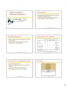
Second level of strides Figure 2.1
A nested-strided operation with two levels of strides.
The second proposal is the nested-strided operation. With this interface, the user can build a vector of strides that define the different levels of stride. From these levels, only the last one represents the placement of data blocks. All other stride levels indicate in which positions does the next level of strides start. Figure 2.1 presents an example of this kind of operations. In this example, there are two levels of strides. The first one indicates that the next level has to be applied three times once every seven elements. The second, and last, level indicates that user wants to access three elements leaving one element between each pair. This last level is used three times as indicated by the first level. The requested elements are represented as the shaded blocks in the figure. Finally, they also propose a nested-batched operation. This operation allows the user to make several simple and nested-strided operations as a single one. In order to do this, the user builds a list with the strided operations to be done. Afterwards, this list is used as one of the parameters in the read or write operation.
Two-Dimensional Files The concept of two-dimensional files was defined as part of the Vesta file system [CF96, CBF93]. In Vesta, a file is made of a set of cells, or partitions, were each of them is divided into Basic Striping Units (BSUs), or registers. Cells are contiguous portions of a file. They are defined at creation time and its number remains constant during the whole life of the file. Each of these cells may be placed in a different I/O node. This means that the number of cells equals the maximum parallelism that can be obtained accessing a given file. This placement is made by the file system with no interaction from the user.
20
CHAPTER 2
Disk-O
Disk-1
DIsk-2
BSUs
Cells
Figure 2.2
Schematic representation of a two-dimensional file in Vesta.
BSUs are sets of bytes that behave as the basic data units used by the repartition mechanism. The size of BSUs is also set at creation time and remains unmodified during the whole life of the file. This division of a file in cells and BSUs allows us to see the file as a two-dimensional array. The cells behave as columns while the BSUs take the place of the rows (Figure 2.2). This interpretation of files as two dimensional arrays allows the user to repartition the BSUs in the same way that array elements can be distributed using High-Performance Fortran [Hig93]. The same partition mechanisms are offered by the system. Any possible partition of the file is what they call a subfile. Actually, a user can only open subfiles and thus when opening a file, the file and the partitioning scheme has to be given as parameters. Using this mechanism, a process can only access the bytes contained in its subfile avoiding any sharing problems.
Data Partitioning in MPI-IO MPI-IO was proposed as an I/O interface standard [MPI96, Mes97, CFF+95]. It is based on the MPI message passing library [Mes94, Mes97]. This interface only allows the user to specify the distribution of the file blocks among the user space. The distribution of this data among the disks is left to the file system underneath.
Parallel/Distributed File Systems
21
File
1
2
3
4
5
6
7
8
9
10
n
12 13 14 15 16 17 18 19 20
etype
filetype
Subfile
1
3
8
9
10 15 16 17
;
buftype
Buffer
2
1
Figure 2.3
2
3
An Example of data partitioning in MPI-IO.
This interface was designed with a very clear set of goals. It was targeted primarily for scientific applications. It favored common usage patterns over obscure ones. It ties to support 90% of parallel programs easily at the expense of making things more difficult in the other 10%. It also intends to correspond to real world requirements and new features are only added when they are proved to be necessary. Finally, the design favors performance over functionality. In MPI-IO, the data partitioning is done in three steps. The first one consists of defining the size of the basic element or etype. This element is used to construct the patterns needed in the next two phases. The second one is done in the open operation and specifies which parts of the complete file will be used to construct the opened subfile. Finally, in the third step, the user defines the accessed elements going to be placed in the buffer. This third step can be done in each read/write operation. These two last steps or mappings are done building patterns from the basic element, or etype, defined in the first step. When a file is opened, the user specifies the filetype which is a pattern of etypes. This pattern defines the subfile to access (Figure 2.3). Using this concept of subfile, the user may specify which blocks are going to be used by each process in the application. Once the subfiles have been specified, every read and write operations may specify a pattern telling the system where to place the elements accessed from the file. This new pattern is also build from etypes and is called bufftype (Figure 2.3). It is
22
CHAPTER 2
important to notice that there are no restrictions when building subfiles and they may be overlapped. Going back to the shared pointers issue, it is straightforward to see now that the global pointer will only make sense if all processes have the same subfile.
2.4.4
Collective I/O
A collective I/O is that situation where all computing nodes cooperate to perform an I/O operations from disk in order to improve its efficiency. This allows the system to build a single big operation from all the small ones requested by each client. In this way, the system is able to obtain more semantic information about the operations and may improve their efficiency. This cannot be done if many small operations are requested at different instants of time. This basic idea has led some very interesting projects such as Two-phase I/O [HdC95, CBM+94, BdC93, dBC93], Jovian [BBS+94] and Disk-directed I/O [Kot95a, Kot95b, Kot94].
Two-phase I/O This I/O strategy involves a division of the parallel I/O task into two separate phases. In the first phase, the parallel data access is performed using a data distribution, stripe size, and set of reading nodes which conforms with the distribution of data over the disks. Subsequently, in phase two, the data is distributed at run time, within the processor array, to match the application's desired data distribution. By employing the two-phase redistribution strategy, the number of requests from the processor array to disks is reduced compared to direct access. Furthermore, the redistribution phase improves performance because it can exploit the higher bandwidths made available by the higher degree of connectivity within the interconnection network of the computational array.
Parallel/Distributed File Systems
23
Jovian Jovian is another run-time library that implements collective I/O. It is based on the idea that applications run alternating computing and I/O phases. As these two phases appear in all members of an application, Jovian synchronizes all of them in each I/O phase. In this way, all I/O operations can be grouped in order to make a collective I/O. At the beginning of an I/O phase, all processes in the application send their request to the processes in charge of the collective I/O. Even if a process does not want to perform an I/O operation, it will also send a request (an empty one). The processes which receive the requests will try to optimize them and access the information from the disks using the most efficient way.
Disk-Directed I/O Finally, Disk-Directed I/O tries to go a little further than the previous proposals. Besides synchronizing all I/O operations, it also tries to send these requests to the disk minimizing the mechanical overheads such as the seek operation. It also improves the performance of the I/O operations overlapping disk accesses with the distribution of the information among the computing nodes.
2.4.5
Interfaces aimed at Multidimensional Arrays
Panda [SW96, SCW+95] provides an interface that eases the work with files that contain multidimensional arrays. When using this interface, the user only has to set some characteristics of the array and some distribution directives. With this information, Panda is able to distribute the array among the disks and nodes very efficiently. Furthermore, as only semantic information is set by the user, this interface becomes very portable. Thus it is very useful to develop parallel applications and kernels.
24
2.5
CHAPTER 2
CACHE: STATE OF THE ART
As far as caches are concerned, there are three main issues that have drawn the attention of researchers in the last years. First, different replacement algorithms have been proposed in order to make the caches more effective. Along with these algorithms, there has also been some work devoted to develop extensible caches where the user can set the replacement algorithms or, at least, give some hints to the system. Second, some studies have been done to examine the influence of the distributed environments on the file-system caches. Finally, some techniques to distribute the cached information among the nodes in the network have also been proposed.
2.5.1
Replacement Policies
When the system decides that a block has to be kept in the cache, we may not have any free buffers in which to place this new block. In such situation, one of the buffers in the cache has to be emptied. The algorithm that decides which block will be discarded is what it is called the replacement algorithm. The more effective this algorithm is, the better the cache behaves. In this subsection, we will explain the three replacement algorithms that have obtained the best results [RL96, KLW94, RD90].
Least-Recently Used (LRU) As can be extracted from its name, this algorithm always replaces the least-recently used block in the cache. This algorithm tries to take advantage of the temporal locality. If a block has been recently used it will probably be used again in a short period of time. On the other hand, if a block has not been used recently, it will probably not be used shortly. This is the replacement algorithm most widely used in commercial file-system caches. Its popularity is due to its high effectiveness and the simplicity of its implementation.
Parallel/Distributed File Systems
25
New block Protected segment
^obe$!g.T.ent, Discarded blocks
Figure 2.4
Flow diagram of blocks in a segmented-LRU cache.
Segmented LRU The idea behind .this algorithm is that blocks which have been requested more than once will probably be used again. In order to take advantage of this heuristic, the replacement algorithm will try to avoid replacing blocks that have been accessed more than once [KLW94]. A segmented-LRU cache is divided into two segments: the probe segment and the protected one. In both segments, all blocks are kept in a queue ordered from the least to the most recently used. When a new block enters the cache it is placed in the probe segment. As it has not been accessed more than once, there is no indication that it will be used again thus it cannot be placed in the protected segment yet. If the user requests a block that it is already in the cache, this block will be placed as the most recently used of the protected segment. This is done because the block has been accessed at least twice and the heuristic says that it will probably be used again. When the system has to discard a block, the least recently used one from the probe segment is discarded. Finally, when a block has to leave the protected segment it will be placed as the most-recently used one of the probe segment. Figure 2.4 shows the flow diagram of the blocks in a segmented-LRU cache.
Frequency-Based Replacement Finally, we present the frequency-based replacement algorithm. The objective of this algorithm is to find the most popular blocks and keep them in the cache. In order to do it, the system keeps a counter-with the number of times each block has been referenced. Whenever a block has to be discarded, the one with the smaller number of references
26
CHAPTER 2
is replaced. Although this is the basic idea, an exact implementation of this algorithm may be very ineffective in some cases. In order to solve problems such as blocks that are accessed many times in a very short period of time and never referenced again, some modifications have been proposed [RD90].
2.5.2
Delayed Write
It is quite straight forward to see that in order to achieve efficient write operations, the physical disk write has to be done in a delayed way. Furthermore, this delayed write may even avoid some disk writes if the block is deleted before reaching the disk. This happens quite often with temporal files or data. On the other hand, this physical write cannot be delayed too long. If the new information is kept from disk too long, the probability of losing the modifications due to a system failure increases. Deciding the best moment to physically write the modified blocks to disk has been studied quite widely [KE93, Kot91, Mog94, RT74]. The most popular proposals try to write the modified blocks either when the buffer is needed, or periodically, or when a buffer is filled completely, or when the disk is idle, etc. The decision of which one is the best depends on whether the efficiency is more important than the fault tolerance or not.
2.5.3
Application-Directed Caches
Although a file-system cache has the potential of improving the performance of the I/O operations, this improvement is not always achieved [Kot91, Smi85]. There are some situations where keeping a file in the cache makes no sense as there is no temporal locality on its usage. If this file is kept in the cache, it will uselessly fill some buffers that might hold some other important blocks. This will decrease the effectiveness of the cache and it may even decrease the I/O performance. For this reason, many systems allow the user to activate/deactivate the caching of a given file [Swe96, CPdA96, CPd+96, Car95, PCG+97, HER+95].
Parallel/Distributed File Systems
27
Another common problem with caches is that the replacement algorithm of a given system may not be the right one for some applications. For this reason, some systems let the user define the replacement algorithm that has to be used with its files. This mechanism has to guaranty that the effectiveness of the cache for the rest of the applications is not damaged by a bad decision made by one application. One of the best examples of one such mechanism was proposed by P. Cao [Cao96, CFL94b, CFL94a]. In her work, she proposes a replacement algorithm with two levels. The application controlled level allows the application to decide which of its cached blocks are to be replaced. The system level controls the number of cache buffers assigned to each application. This two-level replacement algorithm guarantees that an application may only decrease its own performance. This happens because the distribution of buffers among the applications is a task left to the system. Other example can be found in extensible file systems such as ELFS [GL91] and [KN93]. This file systems allows the user to implement the best cache strategies for its application using extensible mechanisms.
2.5.4
Virtual Memory vs. File-System Cache
On one hand, it is a good idea to have big file system caches in order to be very effective. On the other hand, if the cache is too big, the physical memory available for the virtual-memory systems may not be enough. When this happens, the system starts trashing and all the applications slowdown their execution. In order to solve this problem, the Sprite operating system proposes a variable-size cache [Nel90]. This mechanism decides dynamically the portion of physical memory given to the cache and to the virtual-memory system. To avoid trashing, a higher priority is given to the virtual-memory system. With this mechanism memory-bound applications are not affected by the file-system cache. Furthermore, when memory is available, the I/Obound applications may get the advantages of a big cache. This mechanism has been adopted in many modern systems such as HP-UX and Solaris.
28
2.5.5
CHAPTER 2
Multi-level Caching
It is important to notice that caching can be done at many different levels. This is specially important if the environment is a parallel or distributed one. Caching may be basically done in the disk controllers, in the servers, in the client nodes, in the I/O libraries, etc. Plenty of researching has been focused on studying the influence of the different levels of cache [Car95, KLW94, Hel93, NW088, Smi85]. As a common result of these studies, it has been shown the convenience of having more than one level of caches, although it has also been shown that higher level caches decrease the hit ratio of the lower level ones. This happens because the higher level caches absorb most of the locality.
2.5.6
Cooperative Caches
A cooperative cache is a cache that tries to improve the performance of a parallel/distributed file system by coordinating the contents of the caches found in-all nodes. This coordination allows a request from a given node to be served by the local cache of a different node. Until cooperative caching came into sight, all the client caches were isolated and uncoordinated. In order to increase the potential of cooperation, the NOW team proposed the idea of cooperative caching [DWAP94]. This idea was also implemented in xFS which was part of the NOW project [ACPtNt95, ADN+95, Dah95]. Along with the cooperative cache, some algorithms to coordinate the local caches were also proposed. Among all those algorithms, N-Chance Forwarding was presented as the most adequate to coordinate the local caches and still allow them some freedom. A. Leff et al. proposed a similar idea. In their work, they study the impact that could have a coordination of local caches. They also study the impact that replication could have on the system performance [LWY96, LWY93]. Finally, some ideas have been proposed in order to improve the performance of the cooperative caches. For instance, M.J. Feeley proposed a different algorithm to coordi-
Parallel/Distributed File Systems
29
nate the contents of the local caches, which obtained a better effectiveness [FMP+95]. P. Sarkar and J. Hartman also presented a mechanism based on hints that avoided much of the load placed on the managers [SH96].
2.5.7
Cache Coherence
Using file-system caches in different nodes may rise coherence problems. Two nodes may be caching the same file block and this one should be kept coherent when one of the nodes modifies it. To solve this problem, two basic approaches have been followed. The first one consists of relaxing the sharing semantics. This allows simpler and more efficient coherence algorithms. The second approach tries to find efficient algorithms that can fulfill the Unix semantic.
File-sharing Semantics The first relaxation is the session semantic. When this semantic is used, all modifications done on a file are only visible, at the same time, to the processes running on that node. These modifications are not visible by any other process which has this file open and is running on a different node. Once the file is closed, all the modifications become visible to all the applications that open that file after it has been closed by the process which modified it. AFS is an example of file system that uses a session semantic [Kaz88, HKm+88]. For data-base oriented file systems, a transaction semantic has also been proposed. When this semantic is used, all I/O operations are done between two control instructions: begin-transaction and end-transaction. All modifications done between these two instructions will not be visible to the rest of nodes until the transaction is over. Once the transaction is finished, all the modifications done between the control instructions are propagated to the rest of the nodes in an atomic way. This kind of semantic has been used in distributed systems like Cambridge [NH82] or in the distributed shared memory proposed by Feeley [FCNL94].
30
CHAPTER 2
Finally, a semantic where files never change has also been proposed [SGN85]. When this semantic is used, once a file is created it can never be modified. All changes mean a new file (or version).
Coherence Algorithms The first solution, and also the most drastic one, consists of not allowing the caching of write operations when a file is shared. This avoids all coherence problems allowing a Unix semantic. The main problem with this approach is that write operations are much slower than they should be. A similar approach is the one used in the Sprite operating system [NW088]. The second option is based on the use of tokens. When a client wants to write on a file it requests the write-token for that file. As long as a client keeps the token, this client may do as many modifications to the file as needed without asking any more permissions. Whenever another client requests the right to modify that file, the server sends a message to the current owner informing that the token has been revoked. Once the owner acknowledges the token revocation, this token can be handed to the new client. A problem found when protecting coherence with tokens is the revocation mechanism. In order to give the token to a new client, the current owner of the token has to release it and stop making modifications on the file. If the node with the token fails or it is disconnected from the network, there will be no way to revoke the token. And, without the token, no other client will be able to modify the file. In order to solve this problem a new mechanism was proposed: the leases [KM95, Mac94, BHJ+93, MBH+93, GC89]. A lease is very similar to a token but for an expiration time. This means that if a client has a lease to modify a file, this permission will only last for a predefined amount of time. In this way, if the client fails, or it is disconnected, the rest of the clients will only have to wait for the lease to expire in order to get their lease to modify the file. On the other hand, the disconnected client, will stop modifying the file once the lease expires and will have to ask for a new one if it wants to keep modifying the file.
Parallel/Distributed File Systems
31
These two mechanisms, tokens and leases, may be used with different granularity. The first possibility is to use the file as the basic sharing unit. This means that if a client wants to modify a block of a file, it has to request the token or lease of the whole file and no other client may modify any other block. The second possibility is to use the file block as the basic sharing unit. With this granularity many clients may be writing on the same file at the same time, but never on the same block. xFS uses this granularity [Dah95, ADN+95]. Finally, a user defined granularity has also been proposed [Gar96, GCP+96]. Clients define the region they are going to modify which is not necessarily contiguous. Once this region is defined, a client will be able to modify any portion of this region as long as there is no overlapping with other client's region.
2.5.8
Non-Volatile RAM
Due to the decreasing in the price of the non-volatile memories, some researching has been done to use this kind of memories as file system caches. An example is the usage of NVRAM on the client nodes in order to reduce the traffic between the clients and the disk server [BAD+92]. As these caches are non volatile, a more aggressive caching can be done with no loss in reliability.
2.6
PREFETCHING: STATE OF THE ART
Most file systems offer some kind of data prefetching in order to increase the performance of the I/O operations. The most commonly used policy consists of prefetching the next n blocks starting from the one currently requested. Other more sophisticated policies try to discover the access pattern in order to predict which blocks are going to be requested next [Kot91, KE90, Smi85, Smi78]. In this section, we will briefly present some new techniques that have been proposed in order to increase the effectiveness of the prefetching.
32
2.6.1
CHAPTER 2
User-Directed Prefetching
One way to take the predicting task away from the file system, and still be able to do some prefetching, is leaving the task to the application. Applications know, most of the times, the access pattern used in its file better than the system. If good mechanisms are offered to the application to pass this information to the system, a more effective prefetching can be achieved. Based on this idea, a transparent informed prefetching was proposed as part of the Scotch file system [GSC+95, PGG+95, PG94]. This mechanism allows the user to give hints to the system about which blocks are going to be needed in a near future. This information is only a hint to the system that may, or may not, be used in order to prefetch blocks from disk before the application actually needs them. In order to offer the user the possibility to implement their prefetching policies, some systems offer asynchronous reads as part of their interface [ACR95, GL91, HER+95]. This kind of calls give the user all the needed flexibility to implement any kind of prefetching algorithm.
2.6.2
Prefetching via Data Compression
A quite well studied prediction mechanism is the one used in data compression. Datacompression algorithms try to predict which sequences of bytes are more popular to substitute them by shorter ones. As these algorithms are designed to predict the future quite well, why not use them to predict which block to prefetch. Based on this idea several prefetching algorithms have been proposed with quite good results [KL96, VK96, CKV93]. All these algorithms build a probability graph which grows as the system runs. This graph keeps the information of which blocks are more probable to be requested after a given block has been requested. Using this information, the system tries to predict which data blocks will be requested next by the applications.
Parallel/Distributed File Systems
2.6.3
33
Aggressive Prefetching Based on File Openings
In most environments, when a file is opened it is quite easy to predict which files will be opened next. For instance, in a Unix-like environment, once the make executable is opened it is very probable that the files makefile, cc and Id will also be opened in a near future. Using this idea, R. Griffioen and R. Appleton proposed a quite aggressive prefetching algorithm [GA94, GA93]. In their work, they propose that the file system maintains information of which files have been opened after which other files. Using this information, the system tries to predict which files to prefetch once a given file is opened.
2.6.4
Parallel Prefetching
Recently, there has also been a great deal of interest on prefetching from parallel disks as a technique for improving I/O performance of sequential and parallel applications. This research has been focused both from the theoretical and from the practical point of view. Kimbrel et al. have done a theoretical study where several parallel prefetching algorithms are presented [KTP+96, KK96, Kim97], They evaluate them assuming that there is only one process that only has one stream of read requests and that all these accesses are known in advance. This work is a continuation of the one done by Cao et al. where similar algorithms are proposed for a single disk [CFKL95]. Both projects designed prefetching algorithms based on a full knowledge of the access pattern in advance. The Transparent Informed Prefetching also implements parallel prefetching [GSC+95, PGG+95, PG94]. It allows sequential applications which are not able to use more than one disk in parallel to take advantage of all the disks in the system. This is done by prefetching blocks from more than one disk in parallel increasing the I/O performance of these applications.
34
2.7
CHAPTER 2
DISK: STATE OF THE ART
One of the main reasons behind the inefficiency of the I/O operations is the limited speed of the disks. The problem with the disks is that most of the parts are mechanical and cannot keep the pace with electronic components as memory or processing units. Actually, the most important problem with the disks is the seek operation. Moving the heads from one cylinder to another is a very slow mechanical function. To hide this problem, several solutions have been proposed. In this section we will go through the most important ones.
2.7.1
Disk-allocation Policies
A way to avoid the number of seek operations consists of allocating the data of a file in a way that once the first block of the request is accessed, the rest of the blocks can be accessed with the minimal number of seeks [NV77]. Another possible optimization consists of allocating the blocks of a file near their i-node. This avoids the seek operation needed to go from the i-node to the file blocks [TriSO]. Based on the above-mentioned ideas, quite a few allocation policies have been proposed [MK90, Pea92, MJLF84]. Latter studies have shown that all these allocation policies degenerate as the file system ages [SS96, SSB+95]. In order to avoid this degradation of the system, M.K. McKusick presented some modifications to his original algorithm [Com94]. These modifications consist of adding a new step before the physical write to the disk. In this step all contiguous blocks from a file are grouped and try to be written contiguously. This may need some re-allocation of blocks as they where originally allocated to a disk block while they are now written on a different one. Obviously, this mechanism only makes sense if delayed-write policies are used and some blocks from a file can be waiting to be written to disk.
Parallel/Distributed File Systems
2.7.2
35
Log-Structured File Systems
This kind of file systems is based on the assumption that caches obtain very high read hit ratios. As most read operations are handled by the cache, the disk traffic is dominated by write operations. Thus, it seems a good idea to try to improve write operations even if reads are slow-downed a bit. A log-structured file system performs all write operations in a sequential way. This means that a modified block is not overwritten on the same disk block, but written in the next sequential disk block after the last write operation. This behavior emulates a log where old information is never erased but superseded in later page of the log. This organization of the file system increases write operation performance as no seek operations are needed [RO92, Ros92, R090]. Furthermore, as blocks are not overwritten it is quite easy to recover the file system to a consistent state after a failure. As all the information (data and meta-data) is written sequentially, it is very important to have an efficient mechanism to access this information. Actually, once we have the i-node of a file, the algorithm needed to access the file blocks is the same as in the traditional Unix file system. Thus, we have to find an efficient way to locate a given i-node in the log. In this kind of file systems, the i-nodes are not placed in a fixed position that can be calculated using the i-node number. They may be found in any part of the disk. To solve this problem, a new data structure is added to the file system. The i-node map is an array that contains the information on which disk block is kept the last copy of each i-node. As this data structure is compact enough, it can be kept in memory. Thus no disk accesses are needed in order to use it. For fault-tolerance reasons, this i-node map is periodically saved in the disk and can be recovered after a system failure. In Figure 2.5 we present an example of the changes suffered in the structure of the file system when creating files dir/filel and dir/file2. These changes are presented for a traditional Unix-like file system and for a log-structured one. The most important difference is that, in a-traditional Unix-like file system, the meta-data does not change its placement. On thp other hand, the meta-data of the modified file is written
CHAPTER 2
36
Log-structured file system File!
log
dir File 2
Unix-tike file system File!
1dir
B 1
t
File 2
i-node
Figure 2.5 file system.
I Directory
Invalid
Data
i-node map
Differences between a traditional Unix file system and a log-structured
sequentially with the rest of the modified information. It is also important to notice that the information in the directory (i-node and directory) becomes obsolete and it is superseded by a new up-to-date copy in a different disk block. To make this kind of file systems work efficiently, it is necessary to keep large amounts of contiguous free blocks. These free areas are obtained by recovering the blocks that have been superseded by a new version of the information. In order to get these areas big enough there is also the need to compact the file system information and regroup these free blocks. Many algorithms have been presented to solve this problem but their explanation goes beyond the scope of this chapter [Rob96, CS92, Ros92].
Parallel/Distributed File Systems
2.7.3
37
Striping Data Among Several Disks
Another mechanism that is frequently used to increase the disk bandwidth is striping the information among several disks. Thanks to this distribution, information from all disks can be accessed in parallel. This mechanism can be used in two levels. The first one consists of connecting several disks to a single controller board and offers a faster disk to the user. The second level consists of striping the information among several disks attached to different nodes connected through a network.
Redundant -Arrays of Inexpensive Disks (RAID) RAIDs are the first proposal to stripe information among several disks giving the image of a single disk with a higher bandwidth [CLG+94, PGK88, LawSl]. The idea is very simple. It consists of striping the information on several disks in order to make all seek operations in parallel. Furthermore, this mechanism increases the disk bandwidth as many times as disks connected to the board. The main problem presented in this kind of disks is its higher probability of physical failure. It is straightforward to see that the higher the number of disks the probability of one of them failing also increases. In order to solve this problem, five levels of redundancy have been proposed to allow some fault tolerance. These levels go from a complete replication (RAID-1) to an interleaved striping of parity blocks (RAID-5). This last level is the most popular as only the capacity of one disk is wasted due to replication. The main problem found with RAID-5 is that only the failure of one disk at a time is allowed. From this initial model other mechanisms have been proposed to allow the failure of more disks without increasing the portion of disk needed to keep parity blocks [PC96, BM93]. RAID-5 also have an efficiency problem when small writes are requested. If only a portion of the information needed to calculate a parity block is modified, the rest of the information has to be read in order to recalculate the new parity block. Some solutions to this problem will be presented before the end of this chapter.
38
CHAPTER 2
Striping Data among Disks from Different Nodes As the interconnection networks are becoming very fast, we can extend the concept of striping to the whole system. We can scatter information among all disks in the network and, at the same time, be able to access it in an efficient way. The only conceptual difference between a RAID and this new approach is who controls the striping. In a RAID, the controller is the one that strips the information without the knowledge of the file system. With this new approach, it is the file system the one in charge of distributing the information among all the nodes in the network. Obviously, we still have the same problems found in a RAID and similar solutions can be presented. Among the systems that use this mechanism we could name Swift [CL91], Bridge [DS89], RAMA [MK97, MK95] and sfs [VIN+93] among many others.
2.7.4
A Hierarchy of Disks
In a similar way as the main memory hierarchies, some projects have proposed several levels of disks in order to increase their efficiency without losing their reliability.
AutoRAID One of these projects came out with the AutoRAID designed by Hewlett-Packard [WGSS96, WGSS95]. An AutoRAID is made of two levels of RAIDS. The first one works as a cache keeping the most recently modified information. As this disk has to be very fast, a RAID-1 is used. This kind of RAIDs are faster, as keeping the replicated information does not take time but disk space. Furthermore, the small write problem is also avoided. The second level contains the whole file system information and thus cannot waste too much space keeping parity information. For this reason a RAID-5 is used in this second level. The data movement from the first to the second level is done automatically and in a transparent way.
Parallel/Distributed File Systems
39
Disk-Cache Disk (DCD) The idea behind this kind of disk is solving the efficiency problem of the small writes. In order to solve this problem a small disk is used to cache a big one. The first one is structured like a log, thus all the write operations are done sequentially. As this disk does not keep parity information we avoid the small write problem. Later on, when the disk is idle, there is a movement of information from the disk cache to the main disk [HY96].
2.7.5
Using Flash Memory instead of Disks
As the price of flash memories[Adv93, Int94] has dropped dramatically in the last years, some studies have been done in order to use them instead of disks. A. Kawaguchi proposed the implementation of a log-structured file system that uses this kind of memory in a very efficient way [KNM95], There has also been another implementation of file systems on top of flash memories that placed special interest on optimizing transactional operations [WZ94].
2.7.6
Striping and Log-Structured File System
This combination of log-structured file systems and RAID has been widely used as the problems found in one system can easily be solved by the characteristics of the other. Among all this mixed file systems we would like to mention Zebra [HO95, HO92], Sawmill [SO94] and xFS [Dah95, ADN+95].
Zebra In Zebra data is striped among all the disks in the network. In order to solve the smallwrite problem, Zebra takes advantage of the large sequential writes that can be obtained by the log-structured file systems. Each client keep a log of all the modifications done by its clients. Once the log is long enough to fill all the disks, the parity buffer is calculated. Then, the client log and parity block are sent to the disks. This parity can
CHAPTER 2
40
Client 1 log
Client 2 log
Interconnection network
Figure 2.6
Striping based on log-structured file systems as used in Zebra.
be calculated without reading any information from the disks as it will fill a complete line. In Figure 2.6 we present an example of a Zebra file system with two clients and four disks.
Sawmill Sawmill uses a similar technique to the one used in Zebra but using the second generation of RAIDS. The RAID-II architecture was developed to solve the problem found with RAIDS connected to the network [DSH+94, Kat92]. The original idea of a RAID was to offer a very high bandwidth. If we connect this RAID system to a workstation which behaves as a disk server, the bandwidth will by limited by the bandwidth of the workstation's memory. In order to solve this problem, this new RAID architecture allows the disks to be directly connected to the network using an XBUS controller. This avoids the bottleneck of the workstation memory.
Parallel/Distributed File Systems
41
xFS The basic behavior of xFS is very similar to Zebra. The main difference is that xFS is specially designed for scalability. For this reason, the striping is not done on all disks. As proposed for big RAIDs [CLG+94], the system defines stripe groups. Each of these groups of disks works isolated and keeps the parity information without the interaction of any other group. Each client knows to which group it has to write by using a globally replicated stripe-group map. Furthermore, this system tries to set the bases of a new paradigm for network filesystem design, serverless network file systems. While traditional network file systems rely on a central server machine, a serverless system utilizes workstations cooperating as peers to provide all file system services. Any machine in the system can store, cache or control any block of data. A more detailed description of this system is presented in Appendix A as this system will be the performance reference point for the work presented in this thesis.
42
CHAPTER 2
3 METHODOLOGY
3.1
SIMULATOR (DIMEMAS)
All the results presented in this thesis have been obtained through simulation. This mechanism was used so that a wide range of environments and architectures may be studied. The file-system and cache simulator used in our experiments is part of DIMEMAS1 [LGP+96] which is a performance-prediction tool that simulates the behavior of a distributed-memory parallel machine. In this section, we describe the characteristics of DIMEMAS most relevant to this work. We describe the architectural, process, communication and disk models. Finally, we also describe the format of the trace files used by DIMEMAS. ^IMEMAS is a performance-prediction simulator developed by CEPBA-UPC and is available as a PALLAS GmbH product.
43
CHAPTER 3
44
Node O
Figure 3.1
3.1.1
Node!
Node 2
Example of a parallel machine modeled by DIMEMAS.
Architectural Model
The architectural model simulated by DIMEMAS is simple and flexible. It is composed of a set of shared-memory multiprocessors and an interconnection network. Each node in the network has a given number of processors and a private memory. This memory is shared by all the processors in the node and it is only accessible by the processes running on the node. Furthermore, this memory can be used as a communication mechanism between the processes located in the node. Using this model, we can simulate sharedmemory multiprocessors by having a single node. We can also simulate a traditional distributed-memory machine where each node only has one processor. Furthermore, any other configuration in between can also be simulated using this model. DIMEMAS implements two kinds of interconnection networks: bus-based and crossbar. The bus-based interconnection network connects all nodes by a given number of busses and only as many messages as buses can be traveling in parallel. The cross-bar interconnection network simulates that each node can reach any other node using a different path. This means that the system may have as many messages traveling in parallel as the number of nodes multiplied by the number of links each node has. Nodes are connected to the interconnection network through links. Each one of these links allows the node to send a message to the network. This means that a node with four links can send four messages in parallel as long as the interconnection network has enough bandwidth left for them.
Methodology
45
Figure 3.1 presents an example of the typical parallel machine simulated by DIMEMAS. This machine has three nodes with two processors each. All nodes have a local memory, accessible only from the processors located in the node. Furthermore, each node has two links to the interconnection network. In all the experiments run, we have used nodes with only one processor and a cross-bar interconnection network. Furthermore, all nodes only had one input and one output links to the interconnection network unless otherwise specified.
3.1.2
Process Model
DIMEMAS offers a three-level process model as the one proposed in PAROS [LGP+92]. This model is specially designed for distributed-memory parallel machines but can also be used in any other architecture. The three levels are Ptasks, tasks and threads. The Ptask concept refers to a parallel application. This entity owns the resources allocated to the application. In DIMEMAS, a Ptask refers to an application and the processor set where the application is mapped. A task is a logical address space in which one or more flows of control can be executed. Every task is mapped onto one, and only one, node where the physical address space is located. Finally, in the third level, we find the threads. A thread is a flow of control within a task. All threads in a given task share the address space that belongs to their task. All three levels have been used when designing the file system simulated in this thesis. The whole file service is handle by a Ptask, or parallel application and each file server is represented by a task which may have many threads. These threads are the ones that will do all the work as all higher levels are only resource allocation entities.
3.1.3
Communication Model
DIMEMAS offers two communication mechanisms: channels and ports. The first one is designed to communicate threads within a Ptask, or parallel application. On the other
46
CHAPTER 3
hand, ports are the communication mechanism used to communicate threads that are running in different Ptasks. Besides channels and ports, the simulator also offers a fast memory copy operation that can also be included as a communication mechanism. This operation allows an application to copy blocks of memory from one node to another. This operation emulates the block-mover operations currently implemented in most parallel machines [GÍ196, Gra96]. The simulator can emulate several communication models based on two orthogonal semantic aspects: buffering and synchronization. By buffered we mean non rendez-vous communication where both tasks involved in the communication do not need to have reached the communication point before the real data transfer is started. The sender can send the message even if the receiver has not started the receive operation. The message is kept in a buffer until the receiver wants to get the message. By synchronous communication, we understand that the sending task must wait until the data transfer is finished before being able to perform any other useful work. All simulations done in this thesis used buffered and asynchronous communications because it is the most widely used communication model (i.e., PVM [GBDJ93], MPI [Mes94, Mes97], etc.). The communication time is modeled by a linear function (i.e., latency and bandwidth). The latency is the time needed to start a communication and it is assumed to require CPU activity. The bandwidth along with the size of the message is used to compute the time needed by a message to reach its destination once the startup time has finished. The influence of the distance between nodes is considered irrelevant in accordance to the network state of the art. Both, startup and bandwidth depend on whether the communication takes place within a single node or between two different nodes.
Methodology
3.1.4
47
Disk Model
In this work, we have modeled the disk in two different ways. The first one consists of simulating a fixed access time. In this model, reading or writing a block take a fixed amount of time. Although both operation times are constant, they are not necessarily equal and are passed as a parameter to the simulation. This very simplistic model was used during the first part of the thesis (i.e., centralized version) as it simplified the behavior of the system. This eased the task of understanding the way file systems and cooperative caches work. In the second part of this work (i.e., distributed version), we changed the disk model to a linear function similar to the one used in the communication model. The time needed to access information from the disk is divided into two parts: a latency and an access time. The access time is proportional to the disk bandwidth and the size of the information to be read or written. Of course, this size has to be a multiple of the disk-block size. The latency is the time needed to perform all seek and search operations and depends on the kind of operations. Reading from the disk may have a different latency than writing to it. We are aware that both models are probably too simplistic and that a better one could have been used. Anyway, we believe that the results presented in this work are quite independent of the disk model used. The important thing is that accessing the disk takes much longer than accessing a remote memory.
3.1.5
Process-Scheduling Policies
DIMEMAS also simulates several process-scheduling policies. Among all of them we could cite Round-robin, FIFO, Unix SVR4, etc. In all our simulations, we have used round-robin with priorities. All user applications share the processors with the same priority while the file system has a higher priority. This higher priority of the file system is to speed up this service and to avoid it becoming a bottleneck. This policy was chosen because it was the simplest one that allowed processor sharing and a higher priority to the file system. *.
CHAPTER 3
48
Operation Parameters CPU Usage OPEN CLOSE READ WRITE SEEK UNLINK Table 3.1
3.1.6
time consumed file name, file descriptor, flags, initial size file descriptor file descriptor, size file descriptor, size file descriptor, offset, whence file name
Some of the actions that can be represented in a DIMEMAS trace file.
Trace-file Format
The trace file used by DIMEMAS is made of records that describe the possible actions done by an application. Among all possible actions, Table 3.1 shows the ones used in our experiments. In this table, we present the operations and the parameters they need. The behavior of each Ptask is described by one such file, and thus the system needs to have as many trace files as applications. Each of these files describes all actions made by all the threads in the Ptask. It is very important to notice that this trace-file format is quite different from the traditional one used to represent file-system workloads. Traditionally, trace files contain the absolute time when each file-system event took place [BHK+91, KN94, NKP+94]. With this kind of traces, an increase in the performance of the file system could not result in a speed up of the simulated applications. Furthermore, if the file system is able to perform the user request faster than in the original system, this might also increase the number of requests received per unit of time. This cannot be simulated using the old trace format, either. The trace format used by DIMEMAS records the CPU time consumed between two file-system events. This avoids absolute times and the behavior of the simulation gets closer to the one that might be found in a real system. If file-system operations are faster, the application execution time decreases. This kind of effect will be simulated by
Methodology
49
DIMEMAS using the new trace format while it could not be done using the traditional simulators and traces.
3.2
SIMULATION-METHODOLOGY ISSUES
In this section, we describe the methodology issues that are not an implicit part of the simulator. We present the mechanism used to translate the traditional trace files to our new format, the way chosen to communicate applications, the resource consumption, etc.
Trace Files As we have already explained, the traditional trace-file format is not appropriate for our simulation. For this reason, we had to translate the original traces to our new format. The main problem consisted of replacing the absolute time of each event by a relative one. What we did was to use the time interval between two events as the CPU needed between these two events. This is not a perfect translation as the time kept in the trace may be larger than the CPU really consumed by the application. This time interval represents both the time used to perform the operation and the CPU consumed by the application. The problem is that there is no way to know how long the file system operation took in the original execution and thus we cannot compute the exact number of CPU cycles consumed between two I/O operations. The second problem we had was the possibility of race conditions. As the simulated application may start to run faster than the original one, we could simulate a wrong execution due to race conditions. A race condition may appear between read and write operations and between unlink and open operations. The first one does not change the simulation results as we are not concerned about the real contents of the file blocks. As we are simulating, the important thing is that a read or a write operation took place, not the data used. The unlink/open race condition was a bit more dangerous as it could cause very different executions. To solve this problem we renamed all unlinked files every time they were unlinked. This operation was done in the translation of the
50
CHAPTER 3
file and the order used was taken from the absolute times of the original trace file. This guarantees that the simulated execution is very similar to the original one. Finally, we had to map these trace files into the three-level process model. As we only had information about the node where operations took place, we decided to use a very simple mapping. We simulated a single threaded application per node. These applications performed all file-system operations done from their node. We are aware that these traces are not perfect. The format has some small problems such as the race conditions already mentioned. The translation of the CHARISMA and Sprite traces does not reflect the exact behavior originally recorded either as we have not way to get the exact consumed CPU time. Anyway, the problems found in our traces are not as important as the benefits of this new trace format. We can now measure the impact that the performance of the file system has on the applications. We have used the CHARISMA and Sprite traces instead of gathering new traces because both workloads have been studied in detail by the research community. Furthermore, these traces have been used in many file system simulations making our results easier to compare and understand.
Resource Utilization When simulating a file system, it is necessary to emulate a reasonable resource utilization. Most of this utilization has already been described by the different models implemented in the simulator. The communication model defines the contention of the interconnection network, the disk model describes the way disks are accessed, etc. But there are some resources that have to be used and have not been defined yet. The first one consists of the CPU used by the file servers. We have already defined the scheduling policy, but we also need to decide how many CPU cycles these servers will use. Another set of resources that have to be managed are the auxiliary buffers used in delayed operations. As we want to simulate a file system as close to the reality as possible, it has to consume CPU. For this reason, our servers consume a certain amount of CPU after each blocking
Methodology
51
operation (i.e, after receiving a message, after accessing the disk, after a memory copy, etc.). The CPU consumed by the servers depends on how fast the simulated processor was. A second resource that has to be taken into account is the number of auxiliary buffers the system can use. Auxiliary buffers are those buffers where a cache block is kept waiting for a delayed operation. For instance, if a block has to be sent to the disk but this write can wait until the user operation is done, the system will delay this physical write. As the system needs the buffer, the block is temporarily placed in an auxiliary buffer to keep the information. Once the user has been notified, the system can write the block into the disk as a copy of the data is still in the auxiliary buffer. This number of buffers cannot be infinite and thus has to be managed. In our experiments, the system was allowed to use 16 such buffers per node. If an auxiliary buffer was needed in a given node and there were none free, the operation could not be delayed and had to be done in the critical path of the user request.
Communication between Applications The communication model offers three communication mechanisms: channels, ports and memory copies. In our experiments, we have only used two of them. User requests and system notifications are always done using ports while data movement is always done through the memory-copy mechanism. This second mechanism is used as it is faster than sending the information through a port.
Simplicity in the Model In this thesis, we are presenting a way to design and implement cooperative caches and aggressive prefetching. As these were the two main issues in this work, we decided to focus on them and left other related issues in the simplest possible way. We could have used a log-structured file system instead of a traditional Unix-like one. We could have also used different ways to distribute blocks among the disks instead of
52
CHAPTER 3
using an interleaved algorithm. Other replacement policies could have also been used. If none of them was used was to simplify the model. We have always used the most well-known algorithms and mechanisms as they simplify the study of the important issues proposed in this work.
3.3
WORKLOAD CHARACTERIZATION
To test the ideas proposed in this thesis, we need to simulate our proposals under real workloads. We have done this by using two well-known workloads: CHARISMA [KN94, NKP+94] and Sprite [BHK+91, Har93]. The first one describes the load of a parallel machine while the second one describes the load of a network of workstations. In this section, we describe some of the details we think more relevant to the work presented. More accurate descriptions can be found in the literature.
3.3.1
Parallel Workload (CHARISMA)
This trace file was collected from the Intel iPSC/860 at NASA Ames' Numerical Aerodynamics Simulations (NAS). This multiprocessor had 128 computational nodes, each one with 8 MBytes of memory. The information kept in this trace file only contains the operations that went through the Concurrent File System. This means that any I/O which was done through standard input and output or to the host file system was not recorded. The complete trace is about 156 hours long and was collected over a period of 3 weeks in February 1994. To reduce the simulation time, we only used a part of this trace file. We used a two-day period (i.e., February 15th and 16th) which was the busiest one in the whole trace. Incidentally, the first 10 hours were used to warm the cache as we want to study the permanent-state behavior. We have done a study of the workload to get an idea of the load placed on the file system. The results of this study can be seen in Table 3.2 and Figures 3.2 and 3.3. The table presents the total number of operations and accessed SKByte blocks during
Methodology
53
Tota 1 operations blocks
Warm c ache operations
blocks
Read
1021
4919
812
3493
Write
2303
6201
4653
Open
10
Close
10 1
1987 5 5 0.5
11120
2809.5
8146
Unlink Total
3345
Table 3.2 „ Number of thousands of operations and thousands of SKByte accessed blocks in the CHARISMA trace file.
1000000• Write operations « Read operations
g 800000 1 o Id
400000-
Z 200000-
°o
10
•JU
30
Hour
Figure 3.2 Distribution of read and write operations during the simulation on the CHARISMA workload.
the whole simulation. As the simulation only measured what happened after the tenth hour, we have distinguished the load observed in the whole trace and the one found during the simulated period. Both figures present the number of operations and MBytes accessed during the whole simulation. Each bar represents the load observed during an hour of the simulation. Furthermore, each bar is divided into two parts. The dark one represents the load due to write operations and the light one represents the load due to read operations.
CHAPTER 3
54
•Write operations » Read operations
'S loooo s3 er OI
I
5000-
30
Hour Figure 3.3 Distribution of read and written MBytes during the simulation on the CHARISMA workload.
If we examine Figure 3.2, we observe that during some periods of time many operations are requested to the file system while very few ones are requested during other periods of time. A similar behavior is observed in Figure 3.3. The distribution of accessed MBytes is quite uneven. There are very busy intervals and very quiet ones. If we examine both figures in parallel, we detect two basic behaviors. During the busy periods between the 10th and the 26th hours we have very few requests but many MBytes are accessed. This means that most user operations requested very large blocks of information. On the other hand, after the 29th hour, many operations result in a small number of requested MBytes. This means that the user requested very small blocks of information in each operation. We can also observe that more write than read operations are performed while a very similar number of MBytes is accessed by both kinds of operations. This similarity of accessed MBytes seems to go against the results presented in table 3.2. This table shows that more blocks are written than the ones that are read. This difference is because in the figure we show the real number of accessed bytes while in the table blocks are presented. If the user requests only 10 bytes, these ten bytes are accounted as a block that has been accessed in the table while only a 10-byte request is counted in the graphs.
Methodology
55
Tota 1 operations blocks
Warm cache operations Blocks
Read Write
684
868
520
650
225
384
192
306
Open Close Unlink
541
407
530
400
60
48
Total
2040
1252
1567
956
Table 3.3 .Number of thousands of operations and thousands of SKByte accessed blocks in the Sprite trace file.
In this workload, most of the files are between 10 KBytes and l MByte in size. Files are not as big as expected because of the limited disk capacity of the traced system. Other parallel workloads, also studied in the CHARISMA project, showed that parallel environments use larger files. These more adequate traces were not used because only the general results are available, but not the original trace files. Anyway, these files are large enough and are larger than the ones found in traditional mono-processor systems. Regarding the access patterns used by the applications, they are mostly pure sequential and strided. Furthermore, there is plenty of block reutilization which encourages the idea of file-system caching.
3.3.2
Network of Workstation Workload (Sprite)
The Sprite user community included about 30 full-time and 40 part-time users of the system. These users included operating-system researchers, computer-architecture researchers, VLSI designers and "others" including administrative staff and graphics researchers. These traces list the activity of around 50 machines including clients and servers. Although the trace is two days long, all measurements presented in this thesis are taken from the 15th hour to the 48th hour. This is done because we wanted to use the first fifteen hours to warm the cache.
CHAPTER 3
56
100000
• Write operations « Read operations
.2 80000
«2 60000 o tiO) "I 40000 s Z
I •III
20000-
«
10
H
'io' ' ' '
30
40
Hour
Figure 3.4 Distribution of read and write operations during the simulation on the Sprite workload. -• Write operations — Read operations
I
I
I
ma'
10
20
30
40
Hour Figure 3.5 Distribution of read and written MBytes during the simulation on the Sprite workload.
As we did with the CHARISMA workload, we have done a study of the traces and the distribution of the load. This study is reflected in Table 3.3 and Figures 3.4 and 3.5. The meaning of the table and figures is the same as the one presented in the CHARISMA study.
Methodology
57
The first thing that we can observe is that although the load is not evenly distributed through out all the simulated period, the differences are not as big as in the CHARISMA workload. We can also observe that the number of operations and the number of accessed MBytes is much lower than in the CHARISMA workload. This is due to a couple of reasons. First, the trace was taken from a network of workstations where not as many parallel applications where running. Many of the processes that ran on this trace file were editors, shells, administrative software, etc. that do not necessarily place much stress on the file system. The second reason has to do with the age of the traces. These traces are around 7 years old and the stress placed on the file system was not as high as the one we can find today. We can also observe that reads dominate over writes in both number of operations and quantity of accessed MBytes. This differs from the previous study where the load due to both kinds of operations was very similar. This difference is probably due to the different kind of work done under both environments. The size of the files is also smaller than in the previous study. Most of the files are smaller than a few tenths of KBytes. The access pattern used by the application is basically sequential and the sharing of data between applications is not very frequent.
3.4
PARALLEL ENVIRONMENT CHARACTERIZATIONS
Once we have described the workload that will be used in the experiments, we also need to set the parameters of the simulator. As we have two different workloads, we have decided to use two different sets of parameters. The first one simulates a parallel machine and will be used to run the CHARISMA trace file. The second one simulates a network of workstations similar to the one used by the NOW team in their experiments. This second configuration will be used to simulate the Sprite trace file. The actual parameters used in both configurations are presented in Table 3.4. These values will be used through out all this work unless it is otherwise specified.
CHAPTER 3
58
Parallel Machine
NOW
Nodes 128 50 Local-cache size 1 MB 16 MB Buffer size 8KB 8KB Auxiliary buffers per node 16 16 500 MB/s Memory bandwidth 40 MB/s 200 MB/s 19.4 MB/s Network bandwidth Local-port startup 2 //s 50 //s Remote-port startup 10 ¿is 100 /us 1 [J,S Local memory-copy startup 25 us 5 /xs Remote memory_copy startup 50 ßs Number of disks 16 8 Disk-block size 8KB 8KB Disk bandwidth 10 MB/s 10 MB/s Disk-read seek 10.5 ms 10.5 ms Disk-write seek 12.5 ms 12.5 ms Table 3.4
Simulation parameters.
4 COOPERATIVE CACHING AND CENTRALIZED CONTROL
4.1
MOTIVATION
As has already been shown by several'research groups, cooperative caches are a good alternative to improve the performance of parallel/distributed file systems [LWY96, SH96, Dah95, FMP+95]. All cooperative caches implemented so far have been designed with a distributed control to avoid bottlenecks. This distributed control is necessary if many nodes take part in the cooperation. On the other hand, it may not be always necessary when a small number of machines are used in the cooperative cache. It is a good idea to explore the advantages and disadvantages that can be found in a centralized version of a cooperative cache when it is used with a small number of nodes. Furthermore, if we examine most of the currently running parallel machines and networks of workstations, we find that they do not have a great number of nodes. Actually, most of them do not have more than 50 nodes. We will show that, in machines
59
60
CHAPTER 4
with only tenths of nodes, there is no need to have a distributed control in order to obtain an efficient cooperative cache. Among the advantages of a centralized control we can point out its simplicity of implementation. A centralized control is much easier to implement than a distributed one. It avoids all the communication and synchronization problems. Moreover, centralized algorithms have better knowledge of the whole system as they keep all the information of the system. This global information allows the centralized designs to make better decisions to increase the performance of the whole system. The main disadvantage of a centralized control resides in its lack of scalability. Sooner or later, a centralized system becomes a bottleneck and has to be redesigned in a distributed fashion. As we have already mentioned, in this chapter, we will study the viability of implementing a cooperative cache with a centralized control in small machines. A second motivation behind this centralized version was getting a better understanding of the behavior of cooperative caches before trying to build a distributed version. A centralized version is always a useful first step before designing the distributed prototype. As it is much simpler, the results obtained are easier to follow and allow a better understanding of the problems that can be found in a cooperative cache. Once we have a good comprehension of the centralized server behavior, better distributed mechanisms can be designed as we can focus on the distributed part. So far, cooperative caches have been based on the idea of encouraging locality. It is quite reasonable to think that trying to keep as many blocks as possible in the cache of the node that will use them will increase the system performance. The problem is that achieving this locality has a significant overhead. This extra overhead is basically due to reallocation of blocks, replication, maintenance of the coherence, time-consuming remote hits, etc. We are very skeptical about the advantages of a high local-hit ratio compared to the overhead needed to achieve it. We believe,that achieving a high localhit ratio is not the only way to achieve high-performance cooperative caches. We do not say that local hits are bad, but we want to show that it is not the only way to
Cooperative Caching and Centralized Control
61
design this kind of caches. In this first version, we will not encourage locality in order to test if there are other ways to design a fast cooperative cache. In this first version, we also want to study the possibility of avoiding the coherence problem by not allowing replication. This lack of coherence mechanisms would also simplify the design of the cache. Avoiding these mechanisms by not allowing replication also seems to be in the line of not encouraging locality as replication was specially aimed at increasing the local-hit ratio. Finally, this centralized version has to be implemented having in mind that a distributed one will follow. All the algorithms used have to be thought to be easily distributed. If this is not done in this way, many problems might be found when distributing the control. Thus, implementing an efficient distributed version might become a very complex task. In conclusion, we present a cooperative cache with a centralized control as a first step before building a distributed second version. Anyway, it has to be efficient enough to be usable in environments where no distributed control is needed. In order to identify this first centralized version of our cooperative cache we have given it the name of PACA, which stands for PArallel CAche. Actually, as the most important part of this file system is the cooperative cache, we will also use the term PACA when referring to the whole file system.
4.2
FILE-SYSTEM
ARCHITECTURE
Before getting into the details of the cooperative cache, it is necessary to present the architecture of the file system we are working on. As was discussed earlier, this work was designed to run on a parallel machine or network of workstations where each node has a micro-kernel operating system on top. All services, including the file system, are implemented by user-level servers which receive the client requests through ports.
CHAPTER 4
62
Figure 4.1
File-system architecture of the centralized version.
Our centralized version only needs a single file server which takes care of all the tasks related to the file system (Figure 4.1). This file server handles the user requests and sends replies when the work is completed. It also keeps the information about which blocks are cached in which nodes. Finally, it is also in charge of accessing the disk when a requested block is not in the cache. This file server does not need to run on a dedicated node and can share the CPU with any number of clients. To make the service more efficient, the file server has a higher priority than the rest of the applications. This should not be a problem as the server was designed to consume very few resources. The only imposed restriction is that the server should run on the node where the disk, or disks, are connected. This is done to simplify the model easing the task of understanding the results. To increase the performance of the write operations, PACA uses a delayed-write policy. The file-server has a thread, named syncer, that wakes up every 30 seconds. Once it wakes up, it searches for all dirty file blocks and updates them in the disk. This mechanism and interval have been chosen as the ones found in a Unix system [RT74].
Cooperative Caching and Centralized Control
4.3
4.3.1
63
BLOCK-DISTRIBUTION AND REPLACEMENT ALGORITHMS Design Issues
In this subsection, we describe the ideas that have guided the design of both, the blockdistribution and replacement algorithms. We have to have in mind that all of these ideas come from the thesis that achieving a high-local hit ratio is not the only way to achieve a high-performance cooperative cache. If locality is not a key issue in the design, file blocks can be placed in any node. The important thing is to have the blocks in the cache, not their actual location. For this reason, we will place file blocks in any node regardless of the nodes which are going to use them. Second, we will avoid replication. The system will not maintain several copies of the same block, not even in different nodes. Replication has been traditionally used in order to increase the local-hit ratio, but as in our case this is not a key issue there is no need to replicate blocks. Avoiding replication has two important advantages. The first one is that all the buffers in the cache are used to keep different blocks and this should increase the effectiveness of the cache. The second advantage is that avoiding replication also implies that all coherence problems are avoided as will be seen later (§ 4.4).
Finally, our system will also avoid reallocation of information. It is quite typical to keep moving blocks from one node to another to place them in the nodes which will use them. This increases the local-hit ratio but has the overhead of copying blocks through the network. As we want to see if a high-performance cache can be obtained without exploiting the local-hit ratio, it makes no sense to assume the overhead of these extra copies. It is quite obvious that all these ideas go against the goal of achieving a high local-hit ratio. Placing blocks in any node regardless of the location of the clients obviously does
64
CHAPTER 4
not help to have much locality. Furthermore, if replication is not allowed, at most one node can have the block in its local cache. And finally, if data reallocation is forbidden, there is no way to achieve a high local-hit ratio if blocks are requested from different nodes at different times. We will show that using these simple ideas as key issues in the design of a cooperative cache can produce systems as efficient, if not more, as trying to achieve a very high local-hit ratio.
4.3.2
Block Distribution Algorithm
The block distribution algorithm presented in this chapter is very simple. Given the file name (or file-ID) and the block number, the system computes a hash function to decide in which node to place this block. Using this algorithm no replication is allowed as the system will not keep the same file block twice in a single node. Furthermore, there is no way to reallocate blocks as the hash function will always give the same node for a given file block.
destination.node. = fh(fileJD, #block) = (rand(file) + #block)MOD nodes (4.1)
The hash function we have used is quite simple (equation 4.1). We assign a random number to each file the first time this file is used. When a block has to be located, we add this random number to the block number and the result of this operation modulo the number of nodes returns the location of the block in the cache.
4.3.3
Replacement Algorithm
To decide which file block has to be replaced by a new block, we use the well-known least-recently-used replacement algorithm (LRU). As the node of a given file block is predefined by the hash function, this replacement algorithm will only take into account the blocks in the destination node. This means that the server has to keep a different LRU-list for each node as there is no interaction between them. As this replacement
Cooperative Caching and Centralized Control
65
251
f s is I S z-s
j j ICH
O
Figure 4.2
20
40 60 80 % replaced blocks
Approximation of the LRU-Interleaved to a global LRU.
algorithm is based on a LRU and the blocks are distributed in an interleaved fashion, we have named it LRU-Interleaved. Although a different LRU list has been used for each node, it behaves nearly as a global LRU. Figure 4.2 presents a cumulative function that shows whether the replaced blocks were among the least-recently used in the whole cache. To build this graph we have used the results obtained in all the simulations presented in the performance section. We can see that 100% of the replaced blocks using our replacement algorithm were among the 5% least-recently-used blocks in the whole cache. Furthermore, 95% of the replaced blocks were among the 2.5% least-recently-used ones also in the whole cache. This shows that this replacement algorithm behaves much like a global LRU. As each node is treated isolated from the rest of nodes, it should be very simple to distribute the control of the replacement algorithm which was one of the objectives.
4.4
COHERENCE MECHANISM
We have already seen in the state of the art (Chapter 2) that the coherence of the cached data is one of the most important issues in a cooperative cache. Furthermore,
66
CHAPTER 4
if a Unix semantic is to be offered to the user, it becomes even more complex and time consuming. In this work, we present a way to achieve this strict semantic in a very simple and efficient way. This task should not be a very difficult task in a centralized version. As the server has the information of all the blocks, implementing a cache-coherence mechanism should be quite simple. The file server only has to invalidate the obsolete block in its data structures and there are no notifications to be done. The problem is that we want to present a mechanism that, not only works efficiently in a centralized version, but it is also feasible in a distributed one. The origin of all coherence problems comes from the fact that replication of blocks is allowed. As we have mentioned above, this is usually done to increase the local-hit ratio. As we want to see what happens when this issue is not taken into account, we have decided to avoid replication which also means that our cache will not have coherence problems. The only copy of a block that can be found in the cache always has the up-to-date information and no invalidations are ever needed. As can be easily seen, this solution to the coherence problem is also ready to be used in a distributed environment. If good performance can be achieved without encouraging local hits, this is a very simple and efficient solution to the problem.
4.5
ADAPTABILITY TO THE VARIATION OF NODES AND VIRTUAL MEMORY
Finally, there are some environments where it is very important to design mechanisms for the cache to adapt to the variation in the number of nodes and cache sizes. For example, in a network of workstations we should allow the owner of a workstation to isolate its node from the network during a period of time. This user may need the full power of the machine for a given reason and the system should allow the user to have all this power. We should also allow the owner of a workstation to decide the quantity of memory that can be used by the cooperative cache depending on its own needs.
Cooperative Caching and Centralized Control
67
Allowing this kind of variation in the availability of resources can be easily done with very few modifications to the original block distribution algorithm. Whenever a given node decides to start taking part in the cooperative cache, it only has to send a message to the server. From this point on, the server can use the buffers in this node to cache file blocks. On the other hand, if a given node decides to leave the cooperative cache the system has to go through three phases. First, the node requests permission to the file server to leave the cache. Second, the file server sends to disk all modified blocks that are kept in that node. And third, the node is notified that it can use its buffers freely. This variation in the number of nodes implies a change in the hash function to only use the accessible nodes. It may also be necessary to reallocate the already cached blocks as the new hash function may have placed them in a different node. This overhead is not very important as we assume that increasing, or decreasing, the number of nodes should not be a very frequent operation. Thus, it is not a problem to have some extra work when this situation appears. Furthermore, this can be done without stopping the service if an adequate data structure is used during this transition interval. In a similar way, our mechanism could allow a given node to change the size of its local cache in favor of the virtual-memory system as proposed in Sprite [NWO88]. This modification in the number of buffers only needs a message to the server. Sometimes, it will also mean that some modified blocks have to be written to disk before passing the buffers to the virtual-memory system. This variable cache size may affect the performance of the system. As a given subset of all the file blocks will always be placed on the same node, if that node only offers a very small cache, the effectiveness of the cache for those blocks will be very low. This problem has not been solved in this first version but a solution will be proposed in the distributed version presented in Chapter 5.
68
4.6
CHAPTER 4
EXPERIMENTAL RESULTS
In this section, we present the results obtained by the centralized version of the cooperative cache. With these first results we try to obtain a first validation of the ideas we propose in this work. We want to test if a high-performance cooperative cache can be obtained without exploiting locality. We also want to test if avoiding the coherence problem by avoiding replication does not degrade the system performance. Finally, we want to reach a good understanding of the effects these new ideas have on the system performance in order to start the design of the distributed version. These results obtained by our system were compared to the ones obtained by xFS. Actually, they were compared with a centralized xFS version implemented by ourselves. This comparison has not been done with the original distributed version because we wanted to compare PACA with a file system that did not have the overhead of the distributed control. Furthermore, this centralized version did not have the need of a coherence mechanism as the distributed version did. All these simplifications of xFS will ease the task of comparing both systems. Anyway, we should keep in mind that the xFS file system used in this chapter is a simplification of the original one which should be a little bit more efficient than the distributed version as long as it does not become a bottleneck. This centralized version should have similar read performance but write operations should be faster than in the distributed version as it does not have to spend time on the coherence algorithm. In these measures, we have only used one of the workloads (Sprite) presented in chapter 3. This was done because the CHARISMA trace file was taken from a machine with 128 nodes. This machine was too large for a centralized version and we detected that our centralized file system was a bottleneck. On the other hand, the Sprite workload was taken from a network of workstations with 50 nodes which is small enough for a centralized server to handle efficiently. The parameters we used in these simulations are the ones .that emulate a network of workstations which were presented in chapter 3. These parameters have been used because they were also used by the NOW team to test their cooperative cache. As
Cooperative Caching and Centralized Control
Average operation time Local-hit ratio Remote-hit ratio Global-hit ratio
69
Re ad PACA xFS
Wr ite PACA xFS
3454//S 3564/iS
1051/ís
1223//S
65.5% 20.4% 85.9%
2.0% 47.9%
43.5% 0.5% 44.0%
2.9% 82.5% 85.4%
49.9%
Table 4.1 Average operation times and hit ratios obtained using the centralized versions of PACA and xFS.
we want to compare both caches, it seems quite appropriate to use the same network parameters. To study the behavior of both algorithms in different environments, we will also examine the influence several factors such as interconnection-network bandwidth, local-cache size, etc. have on the overall performance.
4.6.1
Algorithm Comparison
The first thing we want to do is a comparison between both file systems in a network of workstations. The results of this comparison are presented in Table 4.1 where we can see that PACA behaves slightly better than the centralized version of xFS. Read operations are 3.1% faster and write operations are 14% faster. This gain may not seem too impressive, specially the one-obtained by read operations. This is true, but the important thing is that similar performance results can be achieved without encouraging a high local-hit ratio (Table 4.1). Furthermore, we have also designed a simpler algorithm that achieves a similar read performance and a higher write performance. To compare these performance results in greater detail, we will first examine the read operations and the write operations will follow. Before starting to explain these results, it is necessary to examine Figure 4.3 along with Table 4.1 in detail. In this graph, we show the whole time spent performing read and write operations by both file systems. It is important to notice that the values represented are not the average operation times, but the total time spent by the file system working on those operations during the whole simulation. Each bar is divided
CHAPTER 4
70
xFS
1 ~| Misses lili"] Remote hits HH Local hits
0.84»
E
- 0.6-
•8 OI
13 § 0.4e Z
0.2n n.
LÜJ
- -,» •
Read
xp
S
PACA
^•" Write
Figure 4.3 Normalized time spent by the centralized version of both file systems serving read and write operations.
into three parts that represent the portion of time spent by the file system working on local hits, remote hits and misses. All these times have been normalized to the time spent by xFS performing read operations in order to make this graph easier to understand. The first thing we observe is that although PACA obtains a much lower read local-hit ratio, very similar average-read times are achieved. On the other hand, if we examine the global-hit ratio and the time spent working on global hits, we observe that they are very similar in both file systems. The reason behind this behavior is the different overhead produced by a remote hit in both file systems. The average time needed to serve a remote hit in xFS is 3.3 time larger than the one needed in PACA. On the other hand, PACA only has 4 times more remote hits than xFS. This means that most of the overhead produced by the larger number of remote hits is outweighed by their higher speed. The rest of the overhead is balanced by the time spent performing local hits as many more have to be served. This difference in the time needed to serve a remote hit between both file systems is explained in the following paragraphs. As xFS tries to increase the local-hit ratio, each remote hit implies a copy of the whole file block from the remote cache to the local cache and a copy of the requested bytes
Cooperative Caching and Centralized Control
71
from the local cache to the user. In PACA, a remote hit only needs one memory copy from the cache to the user address space where only the bytes requested by the user are copied. PACA avoids one copy and the information that goes through the interconnection network is smaller as only the requested bytes are copied, not the whole block. Remote hits take longer in xFS than in PACA also due to the overhead produced by the forwarding of blocks. In xFS, if the block to be replaced is the only copy in the cache, it is not discarded but forwarded to a different node. Actually, a block can only be forwarded twice without being referenced by a client. This forwarding is usually done out of the critical path of the read operation except when all auxiliary buffers are occupied. Auxiliary buffers are those portions of memory where blocks are kept waiting to be forwarded, or sent to disk, until the operation is finished. When there is a lack of such buffers, the block forwarding has to be done before the new block is copied into the buffer. This takes some time and increases the time needed to serve remote hits. If we go back to Figure 4.3, we can also see that, although the miss ratio is very similar, xFS spends a little more time working on them. This also happens due to the forwarding of blocks. As it has just been explained with the remote-hits, this forwarding cannot always be done away from the critical path of the read operation. Let's now compare the behavior of the write operations. The first important thing is that write operations are very fast as they do not usually need to access the disk. This happens because a delayed write policy is used. As write operations are very fast, any overhead has a significant impact on its performance. A clear example can be found in the forwarding of blocks. Both, read and write operations, produce a similar amount of blocks being forwarded, but they have a higher influence on the write than on the read performance. This is the main reason behind the performance loss detected in xFS when compared to PACA. A second difference, but much less important, is the number of misses on dirty. A miss on dirty appears when the block that has to be replaced has been modified but it has not been written to the disk yet. This block has to be written to disk before it is
72
CHAPTER 4
discarded or forwarded. The number of misses on dirty found in xFS is larger than in PACA. This happens because in xFS, blocks are replaced when only about one third of its life time has been consumed. As a block is usually forwarded twice before it is finally discarded, the first time it is forwarded happens after the first third of its life. When this happens, if the block is dirty, it has to be sent to disk before it is forwarded. On the other hand, in PACA, blocks are replaced after all its life time has been consumed. As this time is longer, the probability of a syncer intervention is much higher. If the syncer is able to send the block to the disk before it is discarded or forwarded, this will not have to be done in the critical path of the operation. This explains the higher number of misses on dirty found in xFS when compared to PACA. It is important to notice that the system also tries to perform these physical writes away from the critical path of the operation using a similar mechanism as the one used to delay the block forwarding. The problem is that there are some times when the system runs out of auxiliary buffers to keep this delayed operations. In this case, the physical write has to be done right on the spot.
4.6.2
Interconnection Network Bandwidth Influence
As we have already explained, one of the things we want to study is the effect of not stressing the number of local-hits. This effect will depend on the interconnectionnetwork bandwidth. If a very slow network is available, the importance of the number of local hits will become much more significant in the overall system performance. To study this influence, we have run several simulations varying the interconnectionnetwork bandwidth. In Figure 4.4, we present the results obtained in those simulations. In the graph, the X axis represents the ratio between the bandwidth that can be achieved copying data within a single node and the network bandwidth. As can be seen in Figure 4.4, read operations are faster in PACA than in xFS until the interconnection network is about 6 times slower than the memory bandwidth. As the network slows down, the time needed to serve remote hits also increases. This has a higher effect on PACA than on xFS as our file system has four times more remote hits.
Cooperative Caching and Centralized Control
73
4000 í
3000-
— PACA average READ time -»-PACA average WRITE time ---xFS average READ time --•--xFS average WRITE time
2000-
1000-
1 2 3 4 5 6 (Local-bandwidth)/(Remote-bandwidth) ratio
Figure 4.4 Influence of the interconnection-network bandwidth on the centralized version of PACA and xFS.
PACA
xFS
0.5MB
1MB
2MB
4MB
8MB
16MB
66.2% 63.4%
70.9% 68.6%
76.1% 74.5%
78.2% 78.0%
81.1% 81.3%
85.4% 85.9%
Table 4.2 Influence of the "local-cache" size on the read global-hit ratio using the centralized version of PACA and xFS.
The influence of the interconnection-network bandwidth has a more noticeable effect on the write operation. This happens because, in PACA, nearly all writes mean a remote copy as file blocks are usually placed jn a different node than the clients requesting them. In the other hand, a write operation in xFS nearly always means a memory copy within the same node. For this reason, a slow down in the network bandwidth has a much more noticeable influence on PACA than on xFS.
4.6.3
"Local-Cache" Size influence
Another parameter that has to be studied is the size of the "local-caches". All simulations ran so far have been done using a 16-MByte local cache. Let's now present the results obtained when the machine has "local-caches" ranging from 0.5 MBytes to 16 MBytes (Figure 4.5).
CHAPTER 4
74
8000-
6000-
— PACA average READ time -*- PACA average WRITE time -«- xFS average READ time -- xFS average WRITE time
•o s o u
P 4000-
2000-
5
10
15
"Local-cache" size in MBytes
Figure 4.5 and xFS.
Influence of the "local-cache" size on the centralized version of PACA
The first thing we observe is that the bigger the local caches are, the better the performance on read operations is. This is basically due to the higher global-hit ratio obtained when bigger caches are used (Table 4.2). We also observe that there is a difference in the global-hit ratio obtained by both file systems when local caches are small. This difference is due to the better utilization of the cache made by PACA. As no replication is allowed in PACA, all the buffers are used to keep useful file blocks. On the other hand, xFS allows replication and a percentage of the buffers are used to keep replicated blocks when they could be holding other important blocks which were recently discarded. This difference becomes very important with small caches. As this size increases, the buffers used for replication become less important and end up having no influence. Actually, we can also observe that when large local caches are used, xFS obtains a slightly better global-hit ratio. This is because when big caches are used their replacement algorithm has a slightly better behavior. Anyway, the difference is so small that no noticeable loss in performance has been detected in the system. Write operations have a very different behavior. While in PACA, the write operation is not affected by the cache size, when xFS runs with small caches the same operation
Cooperative Caching and Centralized Control
75
obtains a very poor performance. In PACA, write operations are not affected by the size of the cache because they are not affected by the global-hit ratio. A write miss and a write hit take exactly the same amount of time. In both cases, a copy from the user to the cache is needed. The only difference appears when writing a block implies reading the previous version kept in the disk as only a portion of the block will be modified. This only happens in 1% of the write operations as most of them append information or modify the whole block. A completely different behavior is observed in xFS. The smaller the cache is, the worse the write performance is. This is basically due to a couple of reasons. First, as the cache is smaller, there are less replicated blocks and more blocks have-to be forwarded. Second, as the local cache is smaller, the probability of discarding a dirty block increases. As was explained earlier both, forwarding blocks and cleaning blocks, increase the time of write operations.
4.6.4
Number of Links Influence
A parallel machine may have several links to the interconnection network. These links allow a node to send and receive several data blocks in parallel. To study the influence the number of links has, we have done several simulations using 1, 2 and 4 links (Figure 4.6). We should note that with the current network parameters, 4 links is an impossible combination as the network is only twice slower than the memory. These results, though, may help us understand how would the cache behave if a slower network were used. Let's first examine the impact on read operations. As we can see in Figure 4.6, very little improvement is achieved on read operations. This is because the interconnection network is fast enough to handle read requests and very few requests are sent in parallel. On the other hand, write operations have a higher influence. Increasing the number of links also improves the write average time in PACA. As most of the times, a write operation only implies a memory-copy between two nodes, it is more sensitive to network bandwidth improvements. Besides, the number of bytes requested in write operations is higher than the ones requested in read operations. Thus, more copies can be started in parallel.
CHAPTER 4
76
4000l 1 link 2 links4 links
PACA 3000-
D
xFS
•o
l
S 2000 8 u
1 link 2 links 4 links 1000
Read
Write
Figure 4.6 Influence of the number of links to the interconnection network on the centralized version of PACA and xFS.
We can also observe that xFS is not significantly affected by the number of links. This is due to the high local-hit ratio which avoids most of the network communication.
4.6.5
Single Server Performance
During all simulations, the time needed to perform a local hit, remote hit, miss on clean, etc. has been measured. Afterwards, these results have been compared with the theoretical values and no significant differences have been found. In this environment, and using the Sprite workload, no bottleneck was detected neither in the CPU, nor in the interconnection network, nor in the physical disk access. Another important issue is to examine the effect this file server had on the user work done on the same node. This work was slowed down about 10%. This means that applications can share the processor with the centralized server as long as speed is not crucial. These results prove that a centralized single server can handle the requests of a small network. On the other hand, we have also seen that larger networks like the one we have simulated with 128 nodes are too big for a centralized single server. We started
Cooperative Caching and Centralized Control
77
to simulate the CHARISMA workload on a parallel machine with 128 nodes and we immediately observed that the centralized version became a big bottleneck which led us not to continue those simulations.
4.7
CONCLUSIONS
In this chapter, we have designed and simulated a cooperative cache with a centralized control. We have proven that a centralized control should not be discarded when designing algorithms for parallel machines or networks of workstations with tenths of nodes. We have seen that our centralized version of the cooperative cache works quite well with a network of workstations of 50 nodes. We have also seen that this centralized control is not enough if the network is larger. We have tested it with 128 nodes and the file system has been detected as an important bottleneck. This means that a distributed version has to be designed if large machines are to be used. The second important conclusion is that encouraging high local-hit ratios is not the only way to achieve high-performance caches if the machine has a high-bandwidth interconnection network. We have designed a cache with an extremely low local-hit ratio that obtains similar or even better results than xFS which places much interest on local hits. This happens because keeping a high local-hit ratio places an important overhead on the remote-hits that outweighs the benefits that can be obtained. We can also conclude that the write global-hit ratio does not affect the write operations performance. As write misses take more or less the same amount of time than a write hit, both, hits and misses, are not very different from the performance point of view. Another very important conclusion extracted from this centralized version is that avoiding the cache-coherence problem by avoiding replication is a good solution to the problem. We have seen that, as achieving a local-hit ratio is not the only good solution to achieve high performance, very efficient caches can be designed avoiding replication.
78
CHAPTER 4
Finally, we have presented a distributed replacement algorithm that behaves much like a global LRU. This algorithm can be easily distributed as no communication between nodes should be needed in the distributed version. More information about this centralized version, its characteristics and its performance can be found in earlier papers [CGL96b, CGL95].