Distributed Large Data-Object Environments: End-to-End Performance Analysis of High Speed Distributed Storage Systems in Wide Area ATM Networks William Johnston, Brian Tierney, Jason Lee, Gary Hoo, and Mary Thompson Imaging and Distributed Computing Group, Information and Computing Sciences Division Lawrence Berkeley National Laboratory1, University of California, Berkeley, CA, 94720 Abstract We have developed and deployed a Distributed-Parallel Storage System (DPSS) in several high speed ATM WAN testbeds to support several different types of data-intensive applications. Architecturally the DPSS is a network striped disk array, but is fairly unique in that its implementation allows applications complete freedom to determine optimal data layout, replication and/or coding redundancy strategy, security policy, and dynamic reconfiguration. In conjunction with the DPSS, we have developed a “top-to-bottom, end-to-end” performance monitoring and analysis methodology that has allowed us to characterize all aspects of the DPSS operating in high speed WAN environments. In particular, we have run a variety of performance monitoring experiments involving the DPSS in the MAGIC testbed, which is a large-scale, high-speed, ATM network and we describe our experience using the monitoring methodology to identify and correcting problems that limit the performance of high speed distributed applications. Finally, the DPSS is part of an overall architecture for using high-speed, wide area networks for enabling the routine, location independent use of large data-objects. Since this is part of the motivation for a distributed storage system, we describe this architecture.
1. The work described in this paper is supported by ARPA, Computer Systems Technology Office (http://ftp.arpa.mil/ResearchAreas.html) and the U. S. Dept. of Energy, Office of Energy Research, Office of Computational and Technology Research, Mathematical, Information, and Computational Sciences Division (http://www.er.doe.gov/production/octr/mics), under contract DE-AC03-76SF00098 with the University of California. Authors:
[email protected],
[email protected], Lawrence Berkeley National Laboratory, mail stop: B50B-2239, Berkeley, CA, 94720, ph: 510-486-5014, fax: 510-486-6363, http://www-itg.lbl.gov). This is report no. LBNL-39064.
1
1.0 Introduction We are developing a strategy for using high-speed networks as enablers for storage systems whose components are distributed around wide area networks. The high-level goal is to dramatically increase the location independence for access to “large data-objects”. These objects - typically the result of a single operational cycle of an instrument, and of sizes from tens of MBytes to tens of Gbytes - are the staple of modern analytical systems. It is further the case that many of the instrumentation systems that generate such data-objects are used by a diverse and geographically distributed community: examples from the scientific community include physics and nuclear science high energy particle accelerators and detector systems, large electron microscopes, ultra-high brilliance X-ray sources, etc. There are correspondingly complex instrumentation systems in the health care community that generate large data-objects. Our approach is an architecture that uses a collection of highly distributed services to provide flexibility of managing storage resources, reliability of access, and high performance, all in an open environment where the use-conditions for resources and stored information are guaranteed through the use of a strong, but decentralized, security architecture. In this paper we will discuss some of the aspects of our distributed large data-object architecture, but we focus on the issues for achieving high performance for distributed systems in wide-area ATM networks - a problem that is clearly central to the basic premise of our approach. As developers of high-speed network-based distributed services, we often observe unexpectedly low network throughput and/or high latency. The reason for the poor performance is frequently not obvious. The bottlenecks can be (and have been) in any of the components: the applications, the operating systems, the device drivers, the network adapters on either the sending or receiving host (or both), the network switches and routers, and so on. It is difficult to track down performance problems because of the complex interaction between the many distributed system components, and the fact that problems in one place may be most apparent somewhere else. Further, these distributed applications are complex, bursty, and have more than one connection in and/or out of a given host at one time and simple tools like ttcp do not adequately simulate these conditions. We have developed a methodology and tools for monitoring, under realistic operating conditions, the behavior of all the elements of the application-to-application communications path in order to determine exactly what is happening within this complex system. Our approach is to instrument both the applications and the storage systems to do timestamping and logging at every critical point in the data handling system. We have also modified some of the standard Unix network and operating system monitoring tools to log “interesting” events using a common log format that can be correlated with the instantaneous behavior of the application, the storage system, and the transport between them. This allows us to characterize the performance of all aspects of the distributed systems and network in detail, using “real-world” operations. This monitoring functionality is designed to facilitate identifying bottlenecks, performance tuning, and various sorts of network perfor-
2
mance research. It also allows us to measure throughput and latency characteristics of our distributed application code. The goal of the performance characterization work is to produce predictable, high-speed components that can be used as building blocks for high-performance applications, rather than having to “tune” the applications top-to-bottom as is all too common today. In this paper we describe an architecture for handling large data-objects, the elements, implementation, and applications of that architecture. We also describe in some detail the architecture and performance of a prototype application and a distributed - parallel data server, called the DPSS (Distributed Parallel Storage Server, formerly known as the Image Server System, or ISS) that is used to drive many of the experiments, and is a key element of the large data-object architecture. Finally, we describe some techniques for monitoring and analysis of the elements of the architecture, and some experimental results using these techniques.
2.0 Distributed Large Data-Object Management Architecture The advent of shared, widely available, high-speed networks is providing the potential for new approaches to the collection, storage, and analysis of large data-objects. In one example, high-volume health care image data used for diagnostic purposes - e.g. X-ray CT, MRI, and cardio-angiography - are increasingly collected at tertiary (centralized) facilities, and may now be routinely stored and used at locations other than the point of collection. In this case, the importance of distributed storage is that a hospital (in fact, almost any instrumentation scenario) may not provide the best environment in which to maintain a large-scale digital storage system, and an affordable, easily accessible, high-bandwidth network can provide location independence for such storage. In the case of health care, the importance of remote end-user access is that the health care professionals at the referring facility (frequently remote from the tertiary imaging facility) will have ready access to not only the image analyst’s reports, but the original image data itself. This general strategy extends to other fields as well. In particular, the same basic infrastructure is required for remote access to large-scale scientific and analytical instruments, both for data handling and for direct, remote-user operation. See [1]. The basic elements of a distributed large data-object architecture include:
• data collection and the instrument-network interface • on-line storage that is distributed throughout the network (for both performance and reliability)
• processing elements - also distributed throughout the network - for various sorts of data analysis
• data management that provides for the automatic cataloguing (metadata generation) of the data being stored
• data access interfaces, including application-data interfaces
3
• (transparent) tertiary storage (“mass storage”) management • user access to all relevant aspects (application, data, metadata, data management) • transparent security that provides access control for all of the systems components based on the resource-owner’s policy Within the network storage system in particular - a “middleware” service - the architectural issues include:
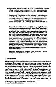
• distributed storage system operation and performance • user access methodologies • security architecture These elements all need to be provided with flexible, location-independent interfaces so that they can be freely moved around the network as required for operational or other logistical convenience. Figure 1 illustrates the overall architecture. It indicates the central role of a high-speed cache, which is used both for initial data collection, and to provide subsequent high-speed access by applications. Briefly, the data flow and information generation proceed as follows. The data-objects are first cached on the DPSS (whose components are frequently scattered all over the network). From the cache it is “processed” as required, but typically to produce several pieces of information to be included in the “index”. Metadata is generated (by analyzing the object, collecting information forwarded by the object generator, or by associating separate information with the object). This metadata is typically kept in “tagged-file” text files. “Derived” information is generated; in the case of image-like objects, this includes typically “thumbnail” and screen-sized representations, “typical” frames from a video-object, etc. The data-object itself is replicated in a tertiary storage system. All of the information related to the data-object is combined into a Web document that represents a comprehensive index and source of meta-information for the data-object. At this point the data-object has a comprehensive “index”, a permanent instance in tertiary storage, and (perhaps) a temporary instance in the network cache. A Web interface can be used for searching, browsing, and accessing the metadata, or the object itself. (See Section 2.3, “Data Management, Mass Storage, and the User Interface” and Figure 3, below.) This same Web interface is used to manage the migration of the data-object in to, and out of, the cache. The user or application never has to deal directly with the tertiary storage system - it is managed in a transparent and location independent manner. Applications that access the data-object can be launched directly from the Web interface, or can use the Web interface to migrate the object to cache, and access it there. Access methods for the data-objects are typically provided as loadable libraries for the application, and provides for application or data specific views of the data-object. (These “objects” are not persistent C++ objects: the “object” consists of access methods (of which there may be several), the metadata (including “derived” objects”), and the data-object itself, all of which typically reside in different locations.) As indicated in Figure 4 (Distributed-Parallel Storage
4
WWW user / application interface
data-object index metadata
cache large data-object location and
large data-object application MSS-1 MSS-2 MSS-3
large data-object access method
high-speed, distributed cache (DPSS)
large data-object generation Figure 1
high-speed WAN
process and index (generate metadata and “derived” objects, as required)
derived data-object(s)
create Web database
store in mass storage system(s)
Overall Architecture for a Distributed, Large Data-Object Environment
System Architecture) the access library translates the application view of the object to DPSS logical block addresses. Together, these elements of a large data-object management architecture have provided effective management for several classes of data-objects. (See [2] and [3].) 2.1 Data Collection Instrumentation systems are at the front-end of many distributed large data-object environments. Examples include particle accelerator detectors, Earth environment monitoring satellites, and medical imaging systems. These sources generate essentially continuous data streams, but ones that have “natural” boundaries that define “objects”. For many of the instrumentation systems that we are interested in, one of the primary issues is
5
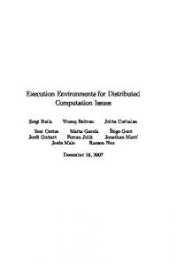
getting the data out of the instruments and onto the network. One of the circumstances that has led to both the interest in, and practicality of, the architecture being described here is that general purpose workstations now have memory and I/O bus structures that are fast enough to acquire, structure, and send to the network, significant bandwidth data streams. (For example, the newest (mid-1996) DEC Alpha and Sun UltraSparc workstations can deliver 20 MBytes/sec of user data to a network interface.) This is an important capability because it means that the only special hardware that is required to bring instruments on-line is the interface between the workstation and the data source, and even this interface may be provided in “software” using off-the-shelf DSP-based I/O boards. The frontend workstation acquires the raw data, formats it as “objects” by adding or using metadata from the experiment environment, and then sends the objects into the distributed environment. The data collection workstation frequently also serves as a buffer so that brief interpretations or slow-downs in the network do not result in loss of data 2.2 Network Cache A high performance widely distributed network storage system is an essential component of a network-based large data-object environment. Distributing the components of a storage system throughout the network increases its capacity, reliability, performance, and security. Usable capacity increases in conjunction with a widely deployed, generalized security infrastructure that can support dynamic construction of systems through brokering and automated acquisition of resources. (See [4].) Reliability increases because storage systems that can be configured from components that have as little as possible in common (e.g., location) provide the resilience that comes from independence (transparent redundancy of data is also possible). Performance is increased by the combined characteristics of parallel operation of many sub-components, and the independent data paths provided by a large network infrastructure. Security is also potentially increased by having many independent components, each of which has local and independent enforcement mechanisms that can limit the scope of a security breach. The Distributed-Parallel Storage System (“DPSS”, also known as the “ISS”) is an experimental system in which we are developing, implementing, and testing these ideas. In most configurations, the DPSS is used as a network-striped disk array designed to supply and consume high-speed data streams to and from other processes in the network. (See [5] and [6].) The DPSS is essentially a “logical block” server whose functional components are distributed across a wide-area network. (See Figure 2) illustrating the DPSS architecture.) The DPSS uses parallel operation of distributed servers to supply image streams fast enough to enable various multi-user, “real-time”, virtual reality-like applications in an Internet / ATM environment. There is no inherent organization to the blocks, and in particular, they would never be organized sequentially on a server. The data organization is determined by the application as a function of data type and access patterns, and is implemented so that a large collection of disks and servers can operate in parallel, enabling the DPSS to perform as a high-speed data source or data sink.
6
block-level access DPSS disk server
DPSS disk server
DPSS disk server
workstation
workstation
workstation
data blocks
data blocks
data blocks
ATM
DPSS
data fragment streams
physical block requests
Figure 2
IP/ATM network (interleaved cell streams representing multiple virtual circuits) returned data stream
∗ logical name translation ∗ data set access control
Client application
logical block requests
DPSS API
ATM
DPSS server
ATM switch
ATM network interface
∗ data structure server
ATM
ATM network interface
single high-bandwidth sink (or source)
Distributed-Parallel Storage System Implementation
At the application level, the DPSS is a semi-persistent cache of named data-objects, and at the storage level it is a logical block server. Although not strictly part of the DPSS architecture, the system is usually used with an application agent library called a “data set structure access method”. This component provides an object-like encapsulation of the data, in order to represent complex user-level data structures so that the application does not have to retain this information for each different data set. The function and interface of the access methods are left to the application domain, but one simple example is for video data. In this case the access method allows applications to request data by “frame” number. The access method converts the application requests into logical block requests. These logical block requests are then sent to the DPSS Master which serves two functions, request and resource management. The Resource Manager maintains data set definitions, and the Request Manager is responsible for mapping the logical block requests to physical block requests. The Resource Manager also deals with interactions with the storage servers to determine available storage (a storage server is an independent entity and may deal with several DPSS Masters) and to establish the “security context” that provides the scope of control for various resources. A security model and supporting security architecture provides for enforcing “owner” defined management policy for the physical resources and access policy for the data.
7
2.3 Data Management, Mass Storage, and the User Interface In any scenario where data is generated in large volumes and with high throughput, and especially in a distributed environment where the people generating the data are geographically separated from the people cataloguing and using the data, there are several important issues: automatic generation of at least minimal metadata; cataloguing of the data and the metadata as the data is received (or as close to real time as possible); transparent management of multiple tertiary storage systems; and facilitation of co-operative research by allowing specified users at local and remote sites immediate access to the data, and incorporation of the data into other databases or documents.
Figure 3
Large Data-Object Management for Video-like Objects
One example of an approach to this capability is “ImgLib” (see [7]) which uses World Wide Web based tools to provide this library-like functionality. Semi-automatic cataloguing of incoming data is done by extracting associated metadata and converting it into text records, by generating auxiliary metadata and derived data, and by combining these into Web documents. Tertiary storage management is provided by using the remote program execution capability of Web servers to provide transparent access to different kinds of mass storage systems that then return the data-objects to the Web server, or, as is the case in several of our applications (and typically with large data-objects), move the data to a DPSS cache for access by applications. (For an example of a Java applet accessing the DPSS, see http://www-itg.lbl.gov/ISS/browser/iss2d.html.) Where the data-object is stored on tertiary storage, and how to access it, are all part of the Web-based “object-index”.
8
Figure 3 illustrates some of these points. It shows a browser interface on the left, and on the right the results of automatically building a sub-collection of data-objects as the result of a search on the textual metadata. The information about the data-objects that result from the search is shown as a collection of thumbnails, associated pointers to other types of derived data, and a pointer to the original data-object. For the data-objects that reside on tertiary storage (a tape-robot based mass storage system in this case), there is an option for forcing migration of a data-object back to the on-line cache if the data of interest is not already there. The example in Figure 3 is fairly simple, but in the health care information system mentioned below, the original video data-object cannot be compressed and requires a special application to view the original data-objects (directly from the DPSS), or via JPEG or MPEG “movies” that are derived representations (see [2]). 2.4 A Health Care Information System Application An example of a medical application that uses this distributed large data-object architecture is a system that provides for collection, storage, cataloguing, and playback of video-angiography images using a metropolitan area ATM network. Cardio-angiography2 is used to monitor and restore coronary blood flow, and though clinically effective, the required imaging systems and associated facilities are expensive. To minimize the cost of such procedures, health care providers are beginning to concentrate these services in a few high-volume tertiary care centers. Patients are typically referred to these centers by cardiologists operating at clinics or other hospitals; the centers then must communicate the results back to the local cardiologists as soon as possible after the procedure. The advantages of providing specialized services at distant tertiary centers are significantly reduced if the medical information obtained during the procedure is not delivered rapidly and accurately to the referring physician at the patient’s home facility. The delivery systems currently used to transfer patient information between facilities include interoffice mail, U.S. Mail, fax machine, telephone, and courier. Often these systems are inadequate and potentially could introduce delays in patient care. (See [3].) Using a shared, metropolitan area ATM network and a high-speed distributed data handling system, video sequences and still images are collected from the video-angiography imaging systems, stored, and accessed by a remote user. The image data are sent through the network to storage and analysis systems, as well as directly to the users at clinic sites. Thus, data can be stored and catalogued for later use, data can be delivered live from the imaging device to remote clinics in real-time, or these data flows can all be done simultaneously. Whether the storage servers are local or distributed around the network is entirely a function of the optimal logistics. There are arguments in regional
2. Cardio-angiography imaging involves a two plane, X-ray video imaging system that produces from several to tens of minutes of digital video sequences for each patient study for each patient session. The digital video is organized as tens of data-objects, each of which are of the order of 100 MBytes.
9
health care information systems for centralized storage facilities away from the hospital environment, even though the architecture is that of a distributed system. (See [8].) This application is in operation in the CalREN, ATM network in the San Francisco Bay Area, and is described in some detail in [2].
3.0 Network Storage: The Distributed-Parallel Storage System A central issue for the approach of using high-speed networks and distributed systems as the foundation of a large data-object management strategy is the performance of the system components, the transport / OS software, and the underlying network. Problems in any of these regimes will negatively affect our strategy, but such problems can usually be fixed if they can be isolated and characterized. A significant part of our work with high-speed distributed systems is developing a methodology and tools to locate and characterize bottlenecks. We have designed and implemented the DPSS, as part of an DARPA-funded collaboration known as the MAGIC gigabit testbed3 (see [9]), and as part of the U.S. Department of Energy’s high-speed distributed computing program. This technology has been quite successful in several environments. The DPSS provides an economical, high-performance, widely distributed, and highly scalable architecture for caching large amounts of data that can potentially be used by many different users. Our current implementation provides for real-time recording of, and access to large, image-like, read-mostly data sets. In the MAGIC testbed, the DPSS is distributed across several sites separated by more than 1000 Km of high speed network that uses IP over ATM as the network protocol, and is used to store very high resolution images of several geographic areas. The first client application of the DPSS was “TerraVision”, a terrain visualization application that uses the DPSS to let a user explore / navigate a “real” landscape represented in 3D by using ortho-corrected, one meter per pixel images and digital elevation models (see [10]). TerraVision requests from the DPSS, in real time, the sub-images (“tiles”) needed to provide a view of a landscape for an autonomously “moving” user. Typical use requires aggregated data streams as high as 100 to 200 Mbits/sec. Even in the current prototype system the DPSS is easily able to supply these data rates from several disk servers distributed across the network. The combination of the distributed nature of the DPSS, together with the high data rates required by TerraVision and various load simulators, makes this a good system with which to test a high-speed network in a much more realistic manner than ttcp-like tools allow.
3. MAGIC (Multidimensional Applications and Gigabit Internetwork Consortium) is a gigabit network testbed that was established in June 1992 by the U. S. Government’s Advanced Research Projects Agency (ARPA). The testbed is a collaboration between LBNL, Minnesota Supercomputer Center, SRI, Univ. of Kansas, Lawrence, KS, USGS - EROS Data Center, CNRI, Sprint, U. S. West, Southwest Bell, and Splitrock Telecom. More information about MAGIC may be found on the WWW at: http://www.magic.net/
10
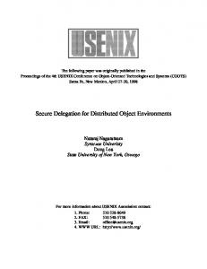
3.1 DPSS Architecture As mentioned, the DPSS is essentially a “logical block” server whose functional components are distributed across a wide-area network. The DPSS uses parallel operation of distributed servers to supply high-speed data streams. The data organization is determined by the application as a function of data type and access patterns, and is implemented during the data load process. The usual goal of the data organization is that data is declustered (dispersed in such a way that as many system elements as possible can operate simultaneously to satisfy a given request) across both disks and servers. This strategy allows a large collection of disks to seek in parallel, and all servers to send the resulting data to the application in parallel, enabling the DPSS to perform as a high-speed data server. The implementation is based on the use of multiple low-cost, medium-speed disk servers which use the network to aggregate multiple server outputs for high performance applications. To achieve high performance all types of parallelism are exploited, including those available at the level of the disks, controllers, processors / memory banks, servers, and the network (see Figure 2). The security model for the DPSS involves accommodating several different resource owners. The context established between the Data Set Manager (DSM) (see Figure 4) and the disk/storage servers reflects agreements between the owners of physical resources (disks) and an agent that is providing storage to a user community. This context enforces the disk usage agreements. The separate context established between the DSM and the users reflects the use-conditions imposed by the data “owner”, and provides for ensuring access control that enforces those use-conditions. For more information on the security architecture see [4]. The overall data flow involves “third-party” transfers from the storage servers directly to the data-consuming application (a model used by most high performance storage systems). Thus, the application requests data, these requests are translated to physical block addresses (server name, disk number, and disk block), and the servers deliver data directly to the application. 3.2 Client Use of the DPSS The client-side (application) use of the DPSS is provided through a library-based API that handles initialization (for example, an “open” of a data set requires discovering all of the disk servers with which the application will have to communicate) and the basic block request / receive interface. It is the responsibility of the client to maintain information about higher-level organization of the data blocks; to maintain sufficient local buffering so that “smooth playout” requirements may be met locally; and to run predictor algorithms that will pre-request blocks so that application response time requirements can be met. The prediction algorithm enables pipelining of the operation of the disk servers with the goal of overcoming the inherent latency of the disks. (See [5] and [6]). None of this has to be explicitly visible to the user-level application, but some agent in the client environment must deal with these issues because the DPSS always operates on a
11
best-effort basis: if it did not deliver a requested block in the expected time or order, it was because it was not possible to do so. In fact, a typical mode of operation is that pending block requests are flushed from the disk server read queues when the next set of requests arrive from the application. Even if the DPSS cannot send all the requested data to the application, it is possible that the data was at least read from disk into the DPSS memory cache, where it will remain available for faster retrieval (for a short time). The application may then routinely re-request some fraction of the data. This deliberate “overloading” of the disk servers ensures that they will be kept busy looking for relevant blocks on disk and caching them in server memory. This approach ensures that the data pipeline stays full, and that disk server resources are never idle. As mentioned, a DPSS client typically communicates with the DPSS through an application library called a “data structure access method library” (see Figure 4).) Disk Servers
returned data stream (“third-party” transfers directly from the storage servers to the application)
∗ block storage ∗ block-level access control
shared security context - 2 shared security context - 1
DPSS Master Resource Manager ∗ allocate disk resources ∗ server/disk resource access control ∗ system security context establishment
physical block requests
Figure 4
Request Manager ∗ logical to physical name translation
single high-bandwidth sink (or source) Application (client)
data
logical block requests
data requests
Application data structure access method (data structure to logical block-id mapping module (library))
Data Set Manager ∗ user security context establishment ∗ data set access control ∗ data set metadata
DPSS API (client-side library)
Distributed-Parallel Storage System Architecture
3.3 DPSS Implementation In our prototype implementations, a typical DPSS consists of several (four - five) Unix workstations (e.g. Sun SPARCStation, DEC Alpha, SGI Indigo, etc.), each with several (four - six) fast-SCSI disks on multiple (two - three) SCSI host adapters. Each workstation is also equipped with an ATM network interface. A DPSS configuration such as this can deliver an aggregated data stream to an application of about 400 Mbits/s (50 Mbytes/s), using these relatively low-cost, “off the shelf” components, by exploiting the parallelism provided by approximately five disk servers, twenty disks, ten SCSI host adapters, and five network interfaces.
12
The software implementation is based on Unix interprocess communication mechanisms and a POSIX threads programming paradigm to manage resources on the disk servers (see [11] and [5]). The primary operating systems (Sun’s Solaris, DEC’s OSF, SGI’s IRIX, and FreeBSD) all have slightly different implementations of threads, but they are close enough that maintaining a single source is not too difficult. The implementation supports a number of transport strategies, including TCP/IP, RTP/IP [12] and UDP/IP. RTP and UDP do not guarantee reliable data delivery and never retransmit. Lost data are handled at the application level. This approach is appropriate when data has an age-determined value: data not received by a certain time is no longer useful, and therefore should not be retransmitted. This is the case for certain visualization scenarios. (This paper, however, focuses on TCP performance issues.) Other papers describing the DPSS, including a paper that describes the implementation is detail [5], are available at http://www-itg.lbl.gov/DPSS/papers.html. 3.4 TerraVision and tv_sim: Prototype DPSS Client and Monitoring Tool TerraVision uses the DPSS client library’s logging facilities to log all data movement events associated with an application session. It uses the a standardized log format to monitor a data block’s progress from the storage server disks, through the network, and into the application client. We have also developed a simulator program, tv_sim, that can generate data requests and receive data blocks from the DPSS in a manner similar to TerraVision’s. Using this program we can generate synthetic request patterns, or repeatedly use actual TerraVision session data request traces, and attempt to verify and analyze performance bottlenecks in the DPSS, the application, or in the network in a controlled environment. TerraVision is a complex software suite running on complex hardware, and patterns of requested data are complex. tv_sim can emulate the TerraVision data request patterns through the trace-driven operation facility, but is a “null” application that can be run at much higher overall request rates than real applications, and can eliminate possible effects of data processing or graphics processing on the network throughput. The tv_sim data request sending rate, in terms of block lists per second and blocks per list, can be set by the user, as can the saving of history logs in the DPSS standard format. The sender can also use trace / playback files of actual TerraVision sessions instead of generating its own lists of block requests, as mentioned above. Additionally, the user can specify the use of multiple data sets, overall running time, and other runtime characteristics. tv_sim and the DPSS thus can be configured to impose almost arbitrary load patterns on a network and to record the results. The TerraVision data request trace is kept in terms of logical block request so that all aspects of the configuration of the DPSS may be changed - the number of storage servers, their location in the network, the data layout, etc. - to facilitate many types of experiments. In other words, real application data request patterns may be applied against different con-
13
figurations of the distributed storage system, network, etc., because the logical block requests are independent of any aspect of the physical organization of the storage system.
4.0 Performance Monitoring Mechanisms Network performance and distributed operation characteristics are obviously an important factor in the architecture that we are describing. There are virtually no behavioral aspects of an ATM “network” that can be taken for granted, even in an end-to-end ATM network. By “network” we mean the end-to-end data path from the transport API through the host network protocol (TCP/IP) software, the host network adaptors and their device drivers, the many different kinds of ATM switches and physical link bandwidths, and then up through the corresponding software stack on the receiver. Further, the behavior of different elements at similar places in the network architecture can be quite different because they are implemented in different ways. The combination of these aspects can lead to complex and unpredictable network behavior. We have built performance and operation monitoring into the storage system and several applications, and have designed tools and methodologies to characterize the distributed operation of the system at many levels. As requests and data enter and leave all parts of the user-level system, synchronized timestamps are logged using a common logging format. At the same time, various operating system and network parameters may be logged in the same format. Several of these instrumented applications and tools are described below. 4.1 DPSS Timing Facility A request for a data block takes the following path through the DPSS (see Figure 5). A request (a list of blocks) goes from the application to the Request Manager, where the logical block names are translated to physical addresses (server: disk: disk offset), then the individual requests are forwarded to the appropriate disk servers. At the disk servers, the data is read from disk into local cache, and then sent to the application (which has connections to all the relevant servers). Precise timestamps are gathered before and after each major function, such as name translation, disk read, and network send. All timestamps are then logged by the DPSS servers. The timestamps are also sent with the data block to the requesting application, where logging can be performed using the DPSS client library. Timestamp consistency is provided by the GPS clock-based network time protocol (NTP − described below), which allows us to make precise throughput and latency measurements throughout the DPSS system and underlying network. Instead of trying to analyze the aggregate delay between sending a request and receiving the associated data block, we can pinpoint delays to within narrowly-specified steps in the data path.
14
to other DPSS servers
DPSS Request Manager (block name translation
TerraVision request blocks
4 ms/block
TS-2
TS-8 TS-0 receive blocks
DPSS disk server TS-3 - recv block list - search cache
Writer 4 ms/block
TS-6 (output to net)
24 ms / block avg. disk to cache
TS-5
TS-4
disk reader
disk reader
= time stamp
Figure 5
TS-7
7 ms/block
memory cache
TS
from other DPSS servers
START
TS-1
disk reader
disk reader
(timings are for a Sun Sparc-10-51, 50 KB blocks)
DPSS Performance Characterization Points and Optimal Average Timings
4.2 OS and Network Layer Monitoring To complement the monitoring at the application level and in the DPSS, we also monitor various operating system and network conditions. We currently collect and log the following types of information: • TCP retransmits • CPU usage (user and system) • CPU interrupts • AAL 5 information • ATM switch buffer overflows • ATM hosts adapter buffer overflow We have modified “netstat” and “vmstat”4 to do logging. netstat provides the contents of various network-related data structures, while vmstat reports statistics on, among other things, virtual memory, disk, and CPU activity. Both programs were modified to present only a relevant subset of their information in the common logging format, and netstat was
15
modified to poll and report continuously (it normally provides only a snapshot of current activity). We typically poll at 100 ms intervals, and since the kernel events are not timestamped, the data obtained this way represents all events in this interval. 4.3 Common logging format To easily process the several gigabytes of log files which can be generated from this type of logging, all events are logged using a common format: keyword; hostname; seconds; nano-sec; data; data; data;......; The logging format is a semi-colon separated list of fields. The “keyword” is a unique identifier describing what is being logged. By convention, the first part of the keyword is a reference to the program that is doing the logging (e.g.: DPSS_SERV_IN, VMSTAT_SYS_CALLS, NETSTAT_RETRANSSEGS, TV_REQ_TILE). Each log record contains both the hostname of the system on which the event occurred and a timestamp. The timestamp is modeled after the format returned from the Unix “gettimeofday” call, and is logged with a numerical precision of one nanosecond. (We expect to be able to get the NTP synchronized accuracy of the timestamps down to better than one microsecond through a combination of the recently increased available precision of GPS signals and the use of real-time clock boards in the systems under study.) The end of every log record can contain any number of “data” elements. These can be used to store any information about the logged event that may later prove useful. For example, for the NETSTAT_RETRANSSEGS event, there is one data element, and it contains the number of TCP retransmits since the previous poll time, and the DPSS_START_WRITE event data elements contain the logical block name, the data set ID, a “user session” ID, and an internal DPSS block counter. The log records for a given data block are associated by virtue of being collected and carried in the data block request message as it works its way through the system. 4.4 Log File Analysis Tools Tools to analyze log files include perl scripts5 to extract information from log files and write data files in a format suitable for using gnuplot6 to graph the results. These tools were used to generate the graphs in Section 5.0. When trying to identify the source of specific problems (such as those that showed up in the early WAN experiments described below) a good deal of exploratory, interactive analysis of the log data was the key to identifying the important factors, and graphical analysis of individual, exceptional events has proven to be the most important aspect of analysis when one is trying to identify the causes of specific behavior. There are several character4. Both netstat (displays network statistics) and vmstat (displays virtual memory statistics) are tools available on many Unix systems. 5. For more information see: http://www.metronet.com/perlinfo/perl5.html 6. For more information see: http://www.cs.dartmouth.edu/gnuplot_info.html
16
istics that have made graphical analysis a powerful technique. What turned out to be the most important was the ability to treat “lifelines” (the temporal trace of a single block from application request all the way through the system to receipt of the data) as identifiable entities that could be individually manipulated and quantitatively analyzed. In order to enable the quantitative analysis of individual events the graphical tools need to have several characteristics. Probably most important is that the significant features (e.g., all of the time points in a lifeline) must be grouped into graphical objects that can be manipulated as units. Further, it turned out that being able to “sketch”, annotate, and create special measurement tools were all important capabilities, and so a versatile graphics drawing tool is very important. (This is illustrated in Figure 7 and Figure 10.) The gnuplot graphics device driver for FrameMaker MIF7 files groups graphics primitives at two levels: the graphics primitives that result from plotting data from one file are one “object”, and at the next level down, each associated set of line segments are sub-objects. Therefore, each of the log file elements, such as block histories, flushed block histories, TCP retransmits, etc., are organized as objects, and the individual block life-lines are kept as sub-objects within these larger objects. The FrameMaker graphics tool can manipulate these objects and sub-objects independently, as well as providing the annotation, measurement, etc., mentioned above, and this proved invaluable in isolating, measuring, and marking significant events. 4.5 Use of NTP To be able to perform meaningful analysis of a network-based system, precise timestamps, based on the synchronized clocks of all systems is essential. All MAGIC testbed hosts run the ‘xntpd’ program [13], which synchronizes the clocks of each host both to time servers8 and to each other. (End-to-end transit times, including speed-of-light and switch delays, are of the order of 10 ms.) The MAGIC backbone segments are used to distribute NTP data, allowing us to synchronize the clocks of all hosts to within about 250 microseconds of each other. The location of the NTP servers in the MAGIC network are shown in Figure 9 (below). This synchronization between host clocks allows us to characterize the operation of the system in useful and surprising ways. (See Figure 7, below.) For example, the DPSS name server, DPSS disk server, and application are typically on different physical hosts scattered over the network. For the events that characterize the operation of the system, 1 millisec-
7. FrameMaker (http://www.adobe.com/prodindex/framemaker/main.html) is a multi-platform desk-top publishing program. MIF is its interchange file format that represents both text and graphics. 8. There is considerable craft and lore in interfacing a precision time source to an NTP server platform, and we readily acknowledge Craig Leres of the LBNL Network Research Group (http://ee.lbl.gov) for working with Dave Mills and his students at Univ. of Delaware to “fine tune” every aspect of the particular GPS clock and server platform OS that we use in our experiments and in the MAGIC testbed. Also see [14] for a description of the characteristics of NTP in the MAGIC environment using this GPS receiver and server combination.
17
ond resolution is enough to establish the relationship between the impact of an event at one point in the network, and the origin of the event somewhere else in the network. Therefore 250 microseconds clock synchronization of all systems is required.
5.0 Example Analysis This section presents some of the types of analysis that we have been able to do using the methodology and tools described in the previous section. The specific examples represent a snapshot of the state of our performance measurements during early 1996. As will be illustrated, there are several aspects of the overall system that dramatically affect performance. Two of these aspects that are changing rapidly are workstation ATM interfaces and ATM switch buffer management, and the numbers quoted here are primarily intended to be illustrative rather than an analysis of specific products. For example, over the past two years the throughput of a Fore Systems SBA-200 interface card operating in a Sun SS-20 has gone from 55Mbits/second to 105 Mbits/seconds, due to upgrades in both OS and device driver software, and in the same time frame the Fore ASX-200 ATM switch buffers have increased in size by 50 times. It is therefore certain that specific numbers like these will have changed by the time this paper is published. The following sections describe performance results and analysis based on our monitoring and logging methodology as applied to the DPSS, TerraVision, and tv_sim programs (described above) operating together in ATM LANs and the MAGIC WAN. 5.1 End-to-End Performance Experiments Experiments have been performed to examine the detailed interaction between a DPSS, whose disk servers are distributed over both ATM LANs and a wide-area ATM network, and the TerraVision application. Our initial monitoring experiments have focused on issues important to high-performance, highly distributed applications such as the TerraVision / DPSS combination. Using the log files described above, we are able to generate graphs (shown in the figures in this section) that have proven to be extremely useful in giving a detailed view of the throughput and latencies at each point in the distributed system: that is, in the application, the DPSS, and in the network. 5.2 LAN Experiments Figure 6 represents a set of traces, collected by monitoring during application-driven operation, that illustrates the general operational characteristics of the DPSS, and specifically shows the strategy used by the TerraVision application in order to keep the overall “pipeline” of the storage system full. Generally, each line style in the graphs indicates data from a different DPSS disk server, and different line styles are also used for “flushed” data requests (described below). The graphs plot “real time” on the horizontal axis, and the monitoring points on the vertical axis. The timestamps are collected at the monitor points, which represent critical points in the data request-response process from application to distributed storage system and back.
18
C
A
D
app_receive
start_write B
end_read
start_read
server_in
master_out
“iss.log” “iss.flush.log”
master_in
Monitor points
app_send
Figure 6
10000
10200
10400
10600
10800
11000
Time (ms) One Server LAN Test (ATM LAN, one SS-20 as server, tv_sim on DEC 3000/600)
(See Figure 5.) Each line − a “life-line” − represents the history of a data block as it moves through the end-to-end path. Referring to Figure 6, TerraVision sends a list of data block requests every 200 ms, as shown by the nearly vertical lines starting at the app_send monitor points. The initial single life-lines fan out at the server_in monitor point as the request lists are resolved into requests for individual data blocks. Each block request is first represented individually in the read queue (start_read). Notice that many life-lines terminate at end_read, and that a few also end at start_read. Any individual data request that is not satisfied by the disk server before the next request list arrives is flushed (discarded) from all the server queues, but the data is retained in the server memory cache. For example, in Figure 6 the life-lines that started at 10,400 ms that were terminated at B did so because the TCP write delay (of unknown cause) at C “trapped” a previous set of blocks in the TCP write buffer. Block requests that were in the DPSS write queue when the next request list arrived (at 10,600 ms) are flushed from the queue. However, some of these blocks were re-requested in the 10,600 ms list, and these re-requests are satisfied very quickly because the data is in the disk server memory cache. This is seen in the nearly vertical life-lines at D . (The “flush on next request” behavior is
19
necessary to avoid deadlocks in the server, and provides a pre-fetch mechanism for the applications.) Referring to Figure 7, using these life-line graphs it is also possible to get fairly detailed F: time for 20 blocks to get from one server writer to the application reader total: 204 ms, avg: 10.2 ms 38.5 Mb/sec
TCP_retrans app_receive
start_write
end_read
G: cache hits start_read
server_in
master_out
A: one disk read faster than the other
B: typical disk read: 22 ms
B: fast disk read: 8 ms
C: 20 block average time to master_in
write blocks to network: 8.65 ms
D: 20 block average time to locate a block (in cache, or not?): 5 ms
points
Monitor
app_send 8000
Figure 7
8200
E: time to read 20 blocks from three disks total:123 ms, avg: 6.15 ms 8 MBy/sec (63.7 Mb/sec)
Time (ms) Detail From a Two Server, LAN, Experiment
information on individual operations within the disk servers. For example, when two life-lines cross in the area between start_read and end_read, this indicates that a read from one disk was faster that a read from another disk. (This phenomenon is clearly illustrated for the server represented by the crossing solid lines in Figure 7 at A .) This faster read might be from disks with faster seek and read times (which is not the case in the experiment represented in Figure 7, as all participating systems used identical disks) or it might be due to two requested blocks being adjacent on disk so that no seek is required for the second block.
20
Further, in Figure 7 we can also see: • at “B” two different characteristic disk reads (one with an 8 ms read time and one with a 22 ms read time); • at “C” the average time to cache a block and enter it into the network write queue is about 8.6 ms; • at “D” the time to parse the incoming request list and see if the block is in the memory cache is about 5 ms; • at “E” the overall server data read rate (four disks operating in parallel) is about 8 MB/sec; • at “F” the actual throughput for this server while dealing with a set of real data requests is about 39 Mb/s (this throughput is receiver limited); • at “G”, there are two cache hits (blocks found in memory) as a result from previously requested, but not sent, data being requested. (Flushed requests are not shown in this figure.) Figure 8 illustrates “correct” operation of multiple servers. This LAN-based two-server TCP_retrans app_receive
Monitoring points
start_write end_read start_read server_in master_out master_in
“iss3.log” “iss2.log”
app_send 8000
8200
8400
8600
8800
9000
9200
Time (ms) Figure 8
Two Server Test (ATM LAN, two SS-20s as servers, tv_sim on DEC 3000/600)
experiment shows the interaction of life-lines for blocks from different servers, and a case where the independent servers are behaving almost “perfectly”: There are very regular block delivery patterns that alternate almost one-for-one between servers. 5.3 Wide Area Network Experiments Of particular interest is the experiment for the three-server configuration operating in the MAGIC WAN testbed (Figure 9). The graphs for the LAN experiments (Section 5.2) show
21
DPSS Master
NTP Server
ATM Switch
MN
DPSS (sender 2)
2
DPSS (sender 1)
OC1
EDC
olis,
eap Minn
US West OC-48
Sprint SONET Network
OC-48
OC
Univ. of Kansas Lawrence, KS
Figure 9
ATM Switch NTP Server
Ka
2
DPSS
X -48
OC
s
nsa
-1
Ft. Leavenworth, KS
700 Km.
Sioux Falls, SD
y, Cit
ATM Switch A
KS
~15 ms latency including two ATM switches
MSCI
Receiver DPSS (sender 3)
Sprint TIOC
The MAGIC Network: Test Configuration
mostly expected behavior: smooth operation, no unexpected latencies, no TCP retransmissions, and so on. However, in the WAN case illustrated in Figure 10, one sees many TCP retransmissions and some extraordinarily long delays (up to 5500 ms). 5.3.1 WAN Experiment Environment End-to-end performance experiments in the wide area use data block request traces from the TerraVision application and then use tv_sim to replay the traces. The traces for the application running in the MAGIC WAN environment were obtained with TerraVision running on an SGI Onyx with eight 150 MHz MIPS R4400 processors, 256 MB of main memory (4-way interleaved), two RealityEngineII graphics processors, and a single Fore Systems 100 Mb/s TAXI ATM interface. (This configuration is the minimum required to get good interactive visualization of 3D landscape.) Experiments were run on the MAGIC ATM testbed, using the configuration illustrated in Figure 9. A five-minute TerraVision session trace of data block requests was captured, and then using this list of block requests, tv_sim was used to repeatedly request and receive those blocks. Experiments were run using a DPSS with one, two, and three disk server configurations. (The number of disk servers is independent of the application data request strategy and transparent to the application, except for establishing the data transfer con-
22
nections). Log files were collected in the various distributed components for satisfied and unsatisfied block requests, TCP retransmission information, CPU usage, and ATM cell loss in the host adapters and ATM switches (though in this case the switches did not accurately report cell loss). 5.3.2 Analysis of a WAN Problem In the early operating environment of MAGIC, it was very difficult to get anywhere near the expected throughput with multiple DPSS servers driving a single application. This resulted in a series of cell-pacing experiments done by our collaborators at U. Kansas, Lawrence (see [15] and [16]) that eventually determined that if every source (e.g. DPSS disk server) was paced at 1/N of the final link bandwidth that the total throughput increased significantly. While this solved an immediate problem, it was not a general solution, so we went back and conducted a series of experiments attempting to pinpoint the specific cause of the problem. These experiments and their results are described in [17]; however, here we illustrate some of the analysis. Referring to Figure 10, first, let us analyze what the performance monitoring shows directly. If we look at the long-delayed block life-lines (emphasized in the figure) we see the characteristic behavior of a data block getting into the write queue (start_write monitor point) and then incurring some very long delays getting to the application. These long delays are almost always accompanied by one or more TCP retransmit events. The reason that the server is blocked as a whole (actually just one application is blocked since each application has its own TCP connection to the disk server) is that once a block is written to the TCP socket, the user level flushes have no effect, and TCP will re-send the block until transmission is successful, even though the data is likely no longer needed and is holding up newer data. The server unblocks when the a retransmission is successful, letting the next write proceed. The impact of this is substantial. Following received data lifelines back in time, the time that the data transfers stalled can be identified. These points are labeled (at the top of the graph) with the subscript “b” for blocked. (The three servers are labeled A, B, and C.) The transmission path (TCP circuit) has recovered when the next transmission proceeds at a “reasonable” rate, and the received data event just prior to the first of a group of “normal” receives is labeled with a subscript “u” for unblocked. At the bottom of the graph, the effective transmission from the servers for this application data path is indicated by the horizontal bars. The impact of this blocking and unblocking is that the effective throughput of all three servers combined (on a 100 Mbit/s data path that has no other traffic) is of the order of 1 Mbit/s. Unfortunately, at the time of this experiment we were not able to get accurate reporting from the switch “A” in Figure 9. However, what we surmise happened is the following. The ATM switch A is where the three server streams come together, and this switch has a per port output buffer of only about 13K bytes. The network MTU (minimum transmission unit) is 9180 Bytes (as is typical for ATM networks). So, the situation is that three sets of 9 KBy IP packets are converging on a link with less than 50% that amount of buffering available, resulting in most of the packets (roughly 65%) being destroyed by cell loss at the switch output port. The TCP congestion window cannot get smaller than the MTU, and therefore TCP’s throttle-back strategy is pretty well defeated: on average, every
23
server A: “tvlog.edc” server B: “tvlog.uswest” server C: “tvlog.tioc” TCP
“edc.net.tcp.retrans.log” “uswest.net.tcp.retrans.log” “tioc.net.tcp.retrans.log”
A:
TCP retrans retransB: missions
C:
app receive
Cb Ab
Bb
Bu
Bb
Cu
Bu Cb
Cu
Cb
Bb
Cu
Bu Cb
Cu Bu Bb Cb
Au
Monitoring points
start write
end read
start read
server in Effective operation of servers due to blockage A: from TCP retransmits masterB: in (white space is C: blocked). Ab, Au, etc., 00 1,000 1000 above, indicate the synchronized blocking of related geographically dispersed servers events
Figure 10
2,000 2000
3,000 3000
4,000 4000
5,000 5000
Time (ms)
Three Server Test (MAGIC ATM WAN, three SS-10s as servers, tv_sim on SGI Onyx)
6000
24
retransmit fails, even at TCP’s “lowest throughput” setting, because this smallest unit of data is still too large for the network buffers. Although we could not “prove” these assertions because we could not get accurate switch cell loss information, this analysis of Figure 10 provided enough information that the network operators upgraded the switch at A. The new switch as 600 KBy of buffering, which allows TCP’s congestion algorithms to work correctly, and throughput is now up to an “average” of 30 Mbit/s per data path, as should be the case. For a more detailed analysis of this experiment, see [17].
6.0 Conclusions In order to achieve high end-to-end performance in widely distributed applications, a great deal of analysis and tuning is needed. In the MAGIC testbed we are evolving a methodology that includes network-wide precision time sources and extensive instrumentation for time, latency, and throughput at all levels of the network, operating system, and applications. We monitor a large collection of parameters simultaneously (from the ATM level all the way up through disk performance on the storage servers and the application’s use of the delivered data) in order to identify and correct performance bottlenecks. This top-to-bottom, end-to-end approach is proving to be a very useful mechanism for analyzing the performance of distributed applications in high-speed wide-area networks, and the type of graphs presented here are very useful and informative. Apart from the immediate need for performance in MAGIC, the larger question that we hope to address by this methodology is whether high-performance use of networks, computing platforms, middleware, and applications has to be treated as a “system” problem (that is, all components considered and optimized together) or whether, as we find and correct problems, we will end up with an environment in which widely distributed, high-performance applications can be build by composing “stock” components, both hardware and software. Some advice for those building distributed applications: timestamp all critical operations using a uniform log format, and run NTP on all hosts, so that the sort of analysis described here is possible.
7.0 Future Work We are refining the tools and the measurement techniques that capture and log events, and several of the other MAGIC consortium members are doing the same. (For example, a number of the “events” currently collected are the results of watching system variables for some interval, and then using the interval mid-point as the time stamp, when we should be getting the actual event timestamp.) We are exploring the use of the University of Kansas “Data Stream Driver” [18] to improve our timing accuracy for operating system events. We hope to be able to use the log files from the DPSS client library as “playback” files for ‘netspec’[19], which is a distributed network performance measurement tool that is being designed and developed at the Telecommunications and Informations Sciences
25
Laboratory, University of Kansas. netspec supports multiple connections per session, and it will support multiple protocols. This will allow us to easily recreate many different traffic scenarios. This work was presented at the 1996 DARPA Workshop on Wide Area ATM Performance (see http://www.tisl.ukans.edu/Workshops/ATM_Performance/), and one result of this workshop is there will be more work put into working with the University of Kansas to incorporate this logging and graphing methodology into netspec to create a general purpose set of tools. This work is ongoing, http://www-itg.lbl.gov/DPSS.
and
progress
reports
will
be
published
at
8.0 References [1]
Johnston, W. and D. Agarwal, “The Virtual Laboratory: Using Networks to Enable Widely Distributed Collaboratory Science” An NSF Workshop, Virtual Laboratory whitepaper. (See http://www-itg.lbl.gov/~johnston/Virtual.Labs.html)
[2]
Johnston, W., Jin Guojun, Gary Hoo, Case Larsen, Jason Lee, Brian Tierney, Mary Thompson, “Distributed Environments for Large Data-Objects: The Use of Public ATM Networks for Health Care Imaging Information Systems”, (http://www-itg.lbl.gov/~johnston/APII.1.1.fm.html)
[3]
Kaiser - LBNL - Philips CalREN project. See http://www-itg.lbl.gov/Kaiser/LKP/homepage.html.
[4]
Johnston, W. and C. Larsen, “Security Architectures for Large-Scale Remote Collaboratory Environments: A Use-Condition Centered Approach to Authenticated Global Capabilities” (draft at http://www-itg.lbl.gov/~johnston)
[5]
Tierney, B., Johnston, W., Chen, L.T., Herzog, H., Hoo, G., Jin, G., Lee, J., “Using High Speed Networks to Enable Distributed Parallel Image Server Systems”, Proceedings of Supercomputing ‘94, Nov. 1994, LBL-35437. Available from http://www-itg.lbl.gov/DPSS/papers.html.)
[6]
Tierney, B., Johnston, W., Herzog, H., Hoo, G., Jin, G., and Lee, J., “System Issues in Implementing High Speed Distributed Parallel Storage Systems”, Proceedings of the USENIX Symposium on High Speed Networking, Aug. 1994, LBL-35775. (http://www-itg.lbl.gov/DPSS/papers.html.)
[7]
ImgLib: See http://www-itg.lbl.gov/ImgLib/ImgLib_intro.html
[8]
Johnston, W. and A. Allen, “Regional Health Care Information Systems: Motivation, Architecture, and Implementation,” LBL Technical Report 34770 (draft), Dec. 1993.
[9]
Fuller, B., I. Richer “The MAGIC Project: From Vision to Reality,” IEEE Network, May, 1996, Vol. 10, no. 3.
[10] Lau, S, and Y. Leclerc, “TerraVision: a Terrain Visualization System,”, Technical Note 540, SRI International, Menlo Park, CA, Mar. 1994. (http://www.ai.sri.com/~magic/terravision.html) [11] Stevens, R. W., TCP/IP Illustrated, Volume 1 The Protocols, Addison-Wesley Professional Computing Series, 1994.
26
[12] Schulzrinne, H., S. Casner, R. Frederick and V. Jacobson “RTP: A Transport Protocol for Real-Time Applications”, An Internet Request for Comments (RFC), January 1996. Available from: ftp://ds.internic.net/rfc/rfc1889.txt [13] Mills, D., “Simple Network Time Protocol (SNTP)”, RFC 1769, University of Delaware, March 1995. (http://www.eecis.udel.edu/~ntp/) [14] Johnston, W., Tierney, B., Herzog, H., Hoo, G., Jin, G., Lee, J. “Time and MAGIC”, from the MAGIC Technical Symposium, Minneapolis, Minnesota, 1994. Available from http://www-itg.lbl.gov/DPSS/talks.html. [15] Evans, Joseph B., Victor S. Frost, Gary J. Minden, “TCP and ATM in Wide Area Networks”, CNRI Gigabit Network Workshop ‘94. (http://www.magic.net/tcp/overview.html) [16] Ewy, B. J., J.B. Evans, G.J. Minden, and V. S. Frost, “TCP/ATM Experiences in the MAGIC Testbed”, Fourth IEEE Symposium of High Performance Distributed Computing, August 1995, pp. 87-93. [17] Tierney, B., W. Johnston, G. Hoo, J. Lee, “Performance Analysis in High-Speed Wide-Area ATM Networks: Top-to-Bottom End-to-End Monitoring”, IEEE Network, May, 1996, Vol. 10, no. 3. LBL Report 38246, 1996. (Also see http://www-itg.lbl.gov/DPSS/papers.html.) [18] Buchanan, B., Menon, R., Niehaus, D, “The Data Streams Kernel Interface”, Telecommunications & Information Sciences Laboratory, University of Kansas, Feb. 1996. [19] Jonkman, Roelof J.T., “An Overview of NetSpec”, Telecommunications & Information Sciences Laboratory, University of Kansas. (http://www.tisl.ukans.edu/Projects/AAI/products/netspec/)
27