DISTRIBUTED MEMS TUNABLE FILTERS D. Mercier, P. Blondy, D. Cros, P. Guillon IRCOM, 123 av. Albert Thomas 87060 LIMOGES cedex – France
[email protected],
[email protected] ABSTRACT This paper focus on the design of MEMS distributed tunable millimeter wave filters. A two pole filter continuously tunable in bandwidth and in frequency with constant input/output impedance is described. The center frequency can be tuned from 37.8 GHz to 40.4 GHz and the bandwidth can be changed from 1.6 GHz to 1 GHz with constant return losses.
INTRODUCTION Recent developments in microelectromechanical system (MEMS) have made possible the design of tunable filters. These filters use micromachined variable capacitors as lumped element to tune frequency and bandwidth (1) (2). Recent researches have demonstrated the possibility to use the frequency response of distributed MEMS transmission lines to design electronic devices like phase shifters or BPSK modulators (3). In this paper we will focus on the design of tunable filters using distributed MEMS transmission lines. The microswitches used are fixed-fixed beam electrostatically actuated.
DISTRIBUTED MEMS TRANSMISSION LINE A CPW line periodically loaded by capacitive bridges microswitch (Fig. 1) behaves like a Bragg resonator with periodic oscillations in the transfer function. Fig. 2 shows that by changing the capacitance values, the transfer function can be shifted in frequency, allowing to change attenuation at a given frequency. This is valid if the spatial bridges periodicity is close to λg/4. On the other hand, if the bridge spatial periodicity is small compared with the wavelength, the loaded line behaves like a slow wave structure, with tunable effective permittivity that can be used to build tunable resonators. The maxima and the minima of the transfer function are used to create different propagative (“propa”) and evanescent (“eva” and “eva2”) sections required to design filters.
DESIGN OF A TUNABLE TWO POLE FILTER The Fig. 3 shows the layout of a two pole filter built with different distributed MEMS transmission line sections. Sections "propa" form the two resonators, the section "eva2" form the inter-resonator couplings and "eva" sections form the input/output couplings. The substrate used is described Fig. 1, its transverse dimensions are: 1 mm Glass, 10 µm BCB, 0.5 µm Gold1, 0.3 µm Alumina (low temperature PECVD), 3 µm Gold2. The bridge width is 60 µm and its length is 300 µm. The impedance of the unloaded line is 97 Ohms resulting in an impedance about 50 Ohms for the loaded line. The different cells are designed to obtain a good compromise between performances and size. The cells "propa" are built with five bridges periodically spaced of 380 µm. these sections are slow wave lines approximately λg/2. The cells "eva" are built with two bridge couples and a 1750 µm CPW line length L approximately λg/4. The cell "eva2" is built with three bridges couples and two 1750 µm CPW line lengths L. We use bridge couples instead of solid wide bridges to allow easy releasing of the structures. The space between two bridges of a couple is 100 µm. The bridges of the cells "eva" and "eva2" are grouped so that
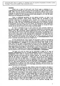
the working frequency is only fixed by the line length L. It has been noticed a problem in the case of a single periodicity of the MEMS bridges for each cells. When the different cells are joined together, the frequency response of the complete filter is disturbed and shifted compared with the frequency response computed for each independent cell. Biasing of the different cells must be separate to allow filter tuning while maintaining the return loss constant. The continuous biasing voltage that drives the membrane movement must also be decoupled from the RF in order to not disturb shunt filter behavior. This decoupling is done thanks to decoupling capacitances at each ends of the membrane (Fig. 1) (4). The decoupling capacitances Cd must be much higher than the bridges capacitances Cb (Cd >> Cb), so that the line sees only the bridges capacitances. Their dimensions are 100*300 µm. A finite element simulation of the CPW line loaded by a MEMS bridge given 8.6 pF for the decoupling capacitance and 33.8 fF to 48.8 fF for the bridge capacitance, when the height of the beam moves of a third of its initial height with 0.3 µm thick alumina. The value of the capacitances versus bridge height is shown Fig. 4.
RESULTS The equivalent RF circuit of a CPW line section loaded by a MEMS bridge is given Fig. 5. As the values of the bridge capacitance have been computed, a circuit software like Agilent ADS can be used to make simulations that take much less time than electromagnetic simulation. The figure 6 allows to validate the equivalent circuit by comparing electromagnetic results and circuit simulation results. It is shown that the results are in good agreement although the S11 of the circuit simulation is a little higher than the S11 of the electromagnetic simulation. The equivalent circuit simulation allows the computation of the external quality factor Qext of the resonators used in the two pole filter. The simulations are computed with the three cells "eva", "propa" and "eva" in cascade. The results are presented Fig 7. Qext vary from 25.4 to 49 for the "eva" cell capacitances going from 33.8 fF to 48.8 fF. The coupling coefficient k is calculated with two pole filter equivalent circuit simulations. Fig. 8 presents the k variations for different “eva2” cell capacitance values. These results are obtained by decoupling the input/output ports. The coupling coefficient value k decreases from 0.047 to 0.023 for the "eva2" cell capacitances going from 33.8 fF to 48.8 fF. As the external quality factor Qext and the coupling coefficient k can be tuned independently the one from the other, the filter can be tuned in center frequency and in bandwidth. Furthermore, although the center frequency is tuned thanks to the "propa" cells capacitances, the other cells capacitances have an influence and must be tuned to maintain the return losses constant in the bandwidth. The results computed for the center frequency variations are presented figure 9. The center frequency can be tuned from 37.8 GHz to 40.4 GHz with the return losses constant in the bandwidth. Also, the bandwidth can be tuned by increasing or decreasing the value of the bridges “eva” cells capacitances. The results are presented Fig. 10. The bandwidth can be tuned from 1 GHz to 1.6 GHz with the constant return losses. The normalized Tchebyscheff filter coefficients g0, g1 and g2 can be deduced from the previous results; their calculated values are g0=1, g1=1.25, g2=1.08 and g3=1.11. When the bandwidth or/and the frequency change, the value of the coefficients remain the same. It means that ∆f/f0 vary (Qext and k vary) although g0, g1 and g2 stay constant. It is well known that the maximum linear displacement of the membrane switch is third of initial height and that it becomes unstable for a displacement higher (5). As the tune in frequency and in bandwidth depends on the MEMS capacitance variations, the maximum tuning range is then limited by the maximum linear displacement of the beam.
A resonator composed of two cells "eva" and a cell "propa" (eva-propa-eva) has been realized. For this first circuit, the BCB layer has been removed from the process. The measurements results (Fig 11) show that the center frequency can be tuned from 33 to 34.4 GHz.
CONCLUSION This paper presents the development of a two pole tunable filter designed with distributed MEMS transmission line. The filter is continuously tunable in frequency and in bandwidth and allows to maintain a constant input/output impedance. The center frequency can be tuned between 37.8 GHz and 40.4 GHz, and the bandwidth can be tuned between 1 GHz and 1.6 GHz.
BCB
Cb
Fig. 1. CPW line (W=G=100 µm, conductor=300 µm) loaded by a electromechanical bridge. eva
propa
eva2
propa
ground micro-
S11 (dB)
Glass
S21 (dB)
Cd
Gold2 Alumina Gold1
eva Frequency (GHz) Fig. 2. Frequency response of a distributed MEMS transmission line for two different beam heights.
Fig. 3. Layout of the two pole filter. Capacitance Cb (fF)
50
CPW
45
Cb L=14 pH
40
35
30 1,2
1,25
1,3
1,35
1,4
1,45
1,5
1,6
1,65
1,7
1,75
1,8
Fig. 5. Equivalent circuit of a CPW line section loaded by a MEMS bridge.
Beam height (µm) Fig. 4. Electromagnetic simulation results for the bridge capacitance Cb when the membrane moves of a third of its initial height h0 (h0=1.8 µm). S21 (dB) S11 (dB)
S21 (dB)
S11 (dB)
Qext =49
Qext =25.4 Frequency (GHz) Fig. 7. Qext variations of a resonator used in the two pole filter design when the “eva” cells capacitances vary from 33.8 fF to 48.8 fF.
Frequency (GHz) Fig. 6. Electromagnetic simulation results (short dash) compared with equivalent circuit simulation results (solid line).
k=0.023
48.8 fF
33.8 fF
k=0.047 S21 (dB)
S21 (dB)
Frequency (GHz)
S11 (dB)
S21 (dB)
Fig. 9. Center frequency variations with return losses constant in the pass band.
S21 (dB)
Fig. 8. Inter resonator coupling k variations for the two pole filter when the “eva2” cells capacitances vary from 33.8 fF to 48.8 fF.
48.8 fF
S11 (dB)
S11 (dB)
Frequency (GHz)
33.8 fF
Frequency (GHz) Fig. 10. Bandwidth variations with return losses constant.
Frequency (GHz) Fig. 11. Frequency shift of single resonator.
REFERENCES (1) H. Kim, J. Park, Y. Kim, Y. Kwon; "Millimeter-wave Micromachined Tunable Filter" 1999; IEEE MTT–S Symp. Dig.; Los Angeles, CA. (2) C. Goldsmith, A. Malczeewski, Z. J. Yao, S. Chen, J. Ehmke, D. H. Hinzel; "RF MEMs Variable Capacitors for Tunable Filters" July 1999; International Journal of RF and Microwave Computer-Aided Engineering; vol. 9; Issue 4; pp. 362-374. (3) N.S. Barker, "Distributed MEMS transmission lines", Ph.D. dissertation, Univ. Michigan, Ann Arbor, 1999. (4) A. Borgioli, Y. Liu, A. S. Nagra, R. A. York, "Low-Loss Distributed MEMS Phase Shifter" IEEE Microwave and guided letters, vol. 10, NO. 1, january 2000, pp. 7-9, 2000. (5) C. Goldsmith, J. Randall, S. Eshelman, T. H. Lin, D. Denniston, S. Chen, B. Norvell, "Characteristic of Micromachined Switches at Microwave Frequencies" IEEE MTT –S Symp. Dig.,San Francisco, CA, pp. 1141-1144, 1996.