Distributed Network Resource Management using a. Multi-Agent System: Scalability Evaluation. Pere Vilà , José L. Marzo, Antonio Bueno, Eusebi Calle, LluÃs ...
Distributed Network Resource Management using a Multi-Agent System: Scalability Evaluation.
Pere Vilà, José L. Marzo, Antonio Bueno, Eusebi Calle, Lluís Fàbrega
Institut d’Informàtica i Aplicacions Universitat de Girona Campus de Montilivi 17071 Girona (Spain) phone: +34 972 418 890 fax: +34 972 418 098 e-mail: { perev | marzo | bueno | eusebi | fabrega }@eia.udg.es Abstract This paper introduces a distributed architecture based on Software Agents, which is devoted to dynamic network resource management. Among others, one of the main objectives of that architecture is to achieve a suitable scalability. This paper presents a scalability study of the proposed Multi-Agent System (MAS) using a mathematical model which has been developed from our experience in the system design and implementation, and also analysing the many simulation results obtained. The MAS results to scale well enough for a wide range of network sizes.
Keywords Multi-Agent System, Network Management, Scalability, Resource Management, Distributed Systems.
1.- Introduction and Background Although the technology of high speed networks offers users increasing transmission capacity, the fact is that the increase in the amount of data to be transmitted is higher than the network capacity. This is due to the high increase in the number of new users and the appearance of new
services (multimedia and interactive resource-consuming services). Therefore, it is clearly necessary to use network resources efficiently.
Large telecommunication companies have been using powerful network management tools, usually based on standards, which provide network statistics and analysis tools to help human network managers in decision-making, manual operation, and programmed periodic readjustments. These centralised decision-making could suffer a scalability problem when excessive network monitoring traffic arises.
Typically the main resource to be managed at this level is the bandwidth or capacity; which requires the network technology to have some kind of reservation mechanism, i.e. the ability to establish Logical Paths (LP) over the physical network. Then, the user connections are established through these LPs. This is the concept of Virtual or Logical Network (Figure 1). The LPs are pre-reservations of bandwidth between different nodes in order to facilitate the establishment of user connections. Main characteristic of this Virtual Network is its flexibility; this means that it is possible to change the logical topology, the capacities assigned to each LP etc. as required and hence the logical network can be adapted to changes in traffic profiles [1][2].
Logical or Virtual Network
Established Logical Paths
Physical Network
Figure 1. Logical Network Concept
The Logical Network can be calculated in an optimisation process given the physical topology, the predicted traffic demands and the performance constraints. However, once the LPs are set up, the initial design may not be optimal due to either discrepancies between the real and predicted traffic patterns or changes in them. Thus an adaptive procedure is required to adjust the Virtual Network bandwidth allocations and topology dynamically. Nowadays this adaptation is usually performed periodically (e.g. every hour, morning / afternoon / night topologies, daily, weekly, etc) on a semi-permanent basis. This is usually done by the management centre because this adaptation typically consists in recalculate the whole Virtual Network topology. However, this brings the problem that the adaptation does not possibly happen when there are congestion problems in the network.
Multi-Protocol Label Switching (MPLS) [3][4], Generalised MPLS (GMPLS) [5][6], and Asynchronous Transfer Mode (ATM) [7][8] are examples of high speed core network technologies capable of establishing LPs.
The proposed system [9] focuses on this idea of logical network, i.e. a dynamically configurable network. The proposed distributed architecture based on software agents groups and integrates several network resource management functions related to the virtual network concept. These functions include load balancing, fault protection and spare capacity management.
1.1.-
Network resource management
Therefore the logical network can be dynamically changed and this implies that the network resources can be adapted to the traffic demand to obtain the maximum performance (and profit) from the available physical resources. There are several mechanisms that can modify this logical network. When these mechanisms can act dynamically at any time the need of co-ordination arises. It is necessary to introduce briefly the mechanisms that are integrated in the proposed architecture.
Load balancing Load balancing attempts to manage the bandwidths assigned to the LPs, i.e. change their bandwidth in order to better adapt the logical network to the offered traffic. When due to unforeseen changes in the offered load some LPs can become underutilised and others congested, i.e. the LP bandwidth is already assigned to several connections and new requests are being rejected, which could be accepted if the traffic loads were better balanced. This is equivalent to the minimisation of the Connection Blocking Probability (CBP).
There are two actions usually performed for the bandwidth management systems in order to increase the bandwidth of a congested LP: re-allocation of bandwidth (using available bandwidth in the link, or using underused bandwidth from other LPs – pre-emption) and rerouting of LPs (the congested LP through an alternative less-congested path) [10].It is preferable re-allocation than re-routing because it is less traumatic for the already established connections going through the congested LP.
Failure protection The ultimate goal of the protection mechanisms is that customers do not notice failures. High speed networks require the utilisation of fast restoration mechanisms that minimise the traffic losses. Fast restoration is achieved by using pre-planned mechanisms, i.e. the use of backup LPs [11] [12] [13]. A working LP can hence be protected using a backup LP (Figure 2). As soon as a fault affecting a working LP is detected, the connections going trough it are rapidly switched over the backup LP with a minimum packet loss. There are several backup techniques, and each one has its advantages and drawbacks [14].
1 Backup LP 1-5
Working LP 1-5 4
2
3 Working LP 6-2
Backup LP 6-2 5
6
Link failure
Figure 2. Working and Backup LPs.
The establishment of backup LPs is usually done by similar means as the working LPs (i.e. using an optimisation procedure for Logical Network design). Anyway, a backup LP is closely related to the working LP it protects and have also to be managed like any other LP (taking into account their special relation).
Spare capacity management Network providers want high revenues. Since bandwidth is an expensive resource, the objective is to minimize the bandwidth reserved for restoration procedures [15] [16] [17]. Therefore, besides the possible decision of protect only the high priority LPs, there is another decision to make: whether to protect the LPs against a single simultaneous failure or to protect them against multiple simultaneous failures. This allows sharing the bandwidth reserved for the backups. The spare capacity reserved for the backup LPs must also be controlled and managed.
Resource management complexity These three management functions are closely related each other. In the case that bandwidth reallocation (increase or decrease) is performed on an LP, then if this LP is protected with a backup LP the amount of spared bandwidth must also be checked and perhaps increased or decreased as well. In the case of LP re-routing then it is possible that the backup LP has also to be re-routed and this would also affect the spared bandwidth in the links. All these interferences have to be taken into account when load balancing is performed.
This is already a quite complex task but, in addition, the abnormal situations in the course of faults have also to be handled. When a fault occurs, the traffic on the affected LPs is automatically switched over the backup LPs. While continuing this situation, the spare bandwidth will be less than the required. Also it could happen that a bandwidth adjustment is required while the traffic is going through the backup LP.
In an ideal world, the perfect load balancing would be done by calculating the optimal logical network (working LPs, backup LPs, and spare capacities) and updating it for every new established connection. This is not possible because of two reasons. First, it is not possible to calculate the optimal Logical Network fast enough since to do that a centralised algorithm is needed. Therefore, this centralised algorithm would need an up-to-date network status view. Second, there would be such a number of bandwidth re-adjustments, re-routings, etc. that a huge amount of management traffic would be generated, reducing instead of increasing the network performance. In order to avoid these problems there must be found a trade-off between the number of readjustments of the logical network and the distance to the optimal configuration.
For these reasons, among others, nowadays network providers typically utilise periodic adjustments (hourly / daily / weekly). These periodic adjustments, however, have the drawback that they cannot cope with short unpredictable changes in the offered traffic load. Therefore there is a need for an automated logical network management which can act when a problem arises. However, the proposal must not provoke performance degradation due to too many changes in the logical network, hence our proposed architecture must not change the logical topology unless there is a persistent problem.
1.2.- Scalability Scalability is a well-studied aspect in the fields of parallel computing and programming. It is also studied from the perspective of distributed systems, e.g. client-server, but these studies usually refer to generic distributed systems or to particular services such as the Web. However,
Network Management systems are different from generic distributed systems and they have special characteristics, for instance they should operate continuously, with high reliability and over several different time scales. Most scalability evaluation methods are based on the instruction count of every function in the system and/or on measures and tests performed in real system implementations. Thus, such evaluation includes both system design and system implementation. We believe that the overall system scalability depends mainly on the system design and architecture, while the implementation details only allow performance tuning and final adjustments.
Finding a scalability metric and comparing different systems is very difficult. In the literature, different scalability definitions are presented:
•
[18] assert that ‘a system is scalable if it can be deployed effectively and economically over a range of different sizes, that are suitably defined’. They define a metric based on the relation between the rate of providing valuable services, the quality of those services and the cost of providing those services.
•
Another definition is proposed in [19] where scalability is considered as a measure of how the performance changes as the system size is increased. The performance is viewed as the response time, as seen by a user under normal working conditions, coupled with the cost of the system – hardware requirements – per user. The authors relate the scalability study with the system design, analysing several characteristics without giving an overall scalability measure. It is also pointed out that network communication is often the key performance limitation.
•
A different definition of scalability is given in [20] where it is defined as “the ability to augment the scope of the system (new functions, new classes, new instances). Network size, configuration and technologies keep changing. Management systems must be able to track and support this evolution in an incremental way without disrupting the service”.
•
Other research, such as [21], define scalability for MAS as “the average measure of the degree of performance degradation of individual agents in the society as their environmental loading, caused by an expansion in the size of the society, increases”.
Thus it can be asserted that there is no clear definition of scalability and even less agreement on a method or measure to evaluate it. As a more generic definition that comprises the above definitions it is possible to say that a “network management system is scalable if its performance does not degrade as the system to be managed grows”.
The scalability problems can arise for different causes or a combination of more than one. These causes can be classified in terms of Processing, Data storage and Communication problems. Processing problems arise when there is insufficient capability to execute the required processes in a node. This includes the lack of memory as well as the lack of computation capacity. Data storage problems arise when a large amount of data has to be stored in a node. Communications problems arise when management messages flood the network. If these three values are maintained under a defined threshold while the network size and number of users increase, then the system is scalable.
In [18] and [22], a scalability metric for distributed systems is presented. This metric encompasses logical and physical system aspects (it is based on a ratio between the system throughput and a combination of response time and cost) and is used for the comparison of two system configurations. The ratio of the two measures indicates whether the system is scalable or not.
It is necessary to evaluate the system scalability in several different sizes, for instance configuration 1 and configuration 2 can be compared using the following ratio, called pscalability:
ΨP =
F (λ2 , QoS 2 , C2 ) F (λ1 , QoS1 , C1 )
(1)
where λ is the throughput, C is the cost and QoS represents a set of parameters that measures the quality of service perceived by users. F is a function which evaluates the performance and the economy of the system. When all scaling variables can be expressed as a function of a parameter k, the scaling of the system can be defined by this scaling factor k. The following Figure 3 shows different scalability situations as a function of this scaling factor.
ψ(k)
(Scalability) Superscalable
Positive Scalability 1.0
Perfect Scalability Threshold Scalability
Unscalable Scale Factor (k)
Figure 3: Different Scalability Behaviours.
This scalability metric cannot be used for direct comparison of different systems. However it is suitable for evaluating the scalability of each system and asserting how well it scales.
1.3.-
Paper organization
Section 2 details the proposed architecture for the Multi-Agent System (MAS) that is in charge of the above described network resource management mechanisms. It also details the MAS characteristics and gives an idea of the implementation. Section 3 presents the mathematical model and the scalability study results. Finally, section 4 shows the conclusions and future work.
2.- Agent System Architecture The complexity of the proposed functions, the desired objectives, and the trends in the network management lead us to propose the use of a Multi-Agent System in a completely distributed architecture. Therefore the proposed architecture will have not a global view of the network status and this inevitably provoke that an optimal logical network configuration cannot be guaranteed. However, as the system starts with an already established logical network, which can be optimally designed, it works making the necessary minimal adjustments in order to adapt that topology when a problem arises, i.e. when an LP becomes congested and new connections are being rejected.
The utilised Software Agents are fixed and distributed over the network elements being managed. This is because this proposal is presented for the management of backbone and core networks, which typically have much bandwidth and they are reliable enough. Therefore it would not be able to take advantage of the especial characteristics of the mobile agents and it is not worthwhile the added complexity of the mobile agent systems [23].
The proposed architecture is presented in Figure 4. There are two types of agents: The Network Monitoring (M) agents and the Network Performance (P) agents. Of course, all the agents are situated at the nodes where the computing facilities are. There is one P agent and several M agents per node.
The M agents are simple reactive agents (lightweight processes) with a stimulus/response type of behaviour, whose main mission is to monitor and control a single LP and react quickly when an event (connection rejections, faults, etc.) occurs. The main task of an M agent is to decide when the monitored LP is congested and warn the P agent. There are many ways to make such a decision, which can be from a simple threshold value to a complex deliberation considering many parameters. It is possible to utilise any of the artificial intelligence techniques for decision making, for instance Case Based Reasoning (CBR), Fuzzy Logic, etc. it is even possible to use
Learning techniques that show the M agents how to detect that the logical path is congested. The technique used is not the point of our work. In the implementation of our system special Functions called Triggering Functions have been designed in order to monitor and detect the LP congestion [24], based on statistics and thresholds. The M agents are also responsible of the switchover mechanism when a failure alarm is received. The M agents’ rules/actions have assigned a priority level, with the highest priority set to the failure-related ones.
M-Agents P-Agent M
P-Agent M
M
Management Plane P-Agent M
M
M
M
P-Agent M
M
M Monitoring and Control Functions
Managed Network Logical Paths Network Nodes
Figure 4. Performance and Monitoring Agents Distribution.
The P agents are more deliberative and each one is responsible of the node where it reside, the outgoing physical links and the supervision and collaboration with the M agents in the same node. The P agent maintains a partial view of the logical network established and is responsible of the co-operation with other P agents (resticted to the physical neighbours). There are two types of communication: co-operation (asking the neighbours for some resources for an already established LP) and negotiation (asking some nodes for the best path to re-route an LP).Using their partial network view and co-operating with their neighbours they are able to solve problems beyond the capacity of any one single agent by pooling their abilities. The proposed MAS also achieves a good robustness, because MAS is a natural way to deploy distributed systems. They have also the ability of working with lack of information and they can easily implement mechanisms in order to collaborate in resuming a failed agent.
Figure 5 shows a network node being managed by one P agent and three M agents. Note that there is an M agent for each logical path starting in the node and there are not any M agents for the logical paths ending or going through that node. Note also that if a logical path is protected by a backup path both are the responsibility of the same M agent, which also could perform the switchover. Figure 5 summarises the main tasks for each agent. P agent M agent LP2 capacity and congestion control
Physical Links (a, b, c) control: -Link capacity -Number of LPs per link -Free capacity per link -Spare capacity per link (reserved in case of failures) Node Control Partial Logical Network view
M agent LP4 capacity and congestion control
M agent LP5 capacity and congestion control
Monitori
LP 4
ng
LP 1
PL b
LP 2 PL a
Back u
LP 3 Logical Path Physical Link
p LP
LP 5 4
PL c
Figure 5. Detail of the Agents Placed in one Node.
2.1.- Partial network view and autonomy When an M agent notifies the P agent that an LP is congested, then the P agent must decide what is the appropriate action to upturn the situation. Usually, the agent will check different possibilities and then decide what is the best action to take. In our proposal, P agents have maximised their autonomy and firstly they try to solve the problem using they partial view of the logical network.
Each P agent has a complete scheme of the physical network, and it is supposed that it does not change. Each P agent maintains two types of information from the logical network: a) the information the P agent is sure about, i.e. the information that is directly monitored by itself and its M agents, and b) the information the P agent is not sure about, i.e. information it has received from other P agents in the past and that could be out of date. This information is updated asynchronously, only when there is a problem and P agents communicate with their neighbours,
then the partial network view of an affected agent is sent attached with the coordination messages. This idea is displayed in Figure 6. We have chosen not to refresh this information regularly so as to avoid having too many coordination messages, which could affect the scalability. This partial network view must only contain information strictly necessary for P agents, and must be coded in small size messages.
Pa1 M
Pa2
Message from Pa1 to Pa2 Partial Network View of Pa1
M
Requested Action
Node 2
Node 1
Response
Partial Network View of Pa2
Message from Pa2 to Pa1
Figure 6. Partial Network Views attached to the P agents’ Messages
Let us suppose that there are no problems in the logical network and therefore P agents are not sending coordination messages. In such a situation there are no refreshing messages between P agents. Suppose now that in this scenario an M agent detects a congested LP. The affected P agent may send a message to one of its neighbours requesting some action, the message has the P agent’s partial view of the logical network attached to it. The P agent that receives the message firstly merges the partial network view of the P agent sender with its own partial network view and then it uses its actualised partial network view to make a decision or take action.
Therefore the agents must make their decisions with partial, incomplete and/or out-of-date information. The main goal of each P agent is to achieve the maximum utilisation of the resources it manages. This objective is equivalent to minimising the Connection Blocking Probability (CBP) for all the LPs that start in a particular node. In order to achieve their goal, P agents must cooperate with each other. Therefore, communication mechanisms and protocols must be used.
2.2.-
Communications
Regarding this communication between P agents there are several options. The use of proprietary protocols, the use of standard agent protocols (typically application level protocols with a rich capacity for transferring knowledge), or even it could be possible to make use of the Operations and Maintenance (OAM) -style of packets by the definition of new types of these special packets or cells.
One of the scalability problems in distributed systems is produced when every agent in the system needs to communicate with all the other agents quite often. In order to assure good scalability we propose the constraint that every P agent can only communicate with its physical neighbours. Of course there are advantages and drawbacks of using this restriction. The advantages are that agents have a limited number of “known” physical neighbours and this simplifies the communication management between the P agents, and helps achieve good scalability. The drawbacks are that communication mechanisms are less flexible and, in most cases, slower due to the hop-by-hop message processing by the P agents. On the other hand, this restriction allows the possibility of establishing special LPs between physical neighbouring nodes for management purposes only. Therefore the communication protocols we propose, situated in an application level, have similarities with the signalling ones. The communication restriction along with the simplicity of the decision making mechanisms of our proposed agents mean that the communication richness in this case is not too high. Although it is perfectly possible to use standardised agent protocols, we have chosen to implement simpler communication protocols.
2.3.-
Implementation and co-ordination
The specific implementation of the network resource management algorithms for the congestion detection, the bandwidth reallocation, the LP re-routing, the failure protection, and the spare capacity management are out of the scope of this article, due to the space limit. This sub-section
is introduced here in order to give an idea of how the proposed architecture has been implemented and tested. For the coordination of all the mechanisms and to avoid interferences between them, we applied the following rules and constraints:
•
The working LP and the backup LP should be increased and decreased accordingly. The decreasing procedure is more or less straight, however in the increasing process the proposed MAS tries to increase both the working LP and the backup LP simultaneously. If one of them or both fail, then the increasing process is aborted.
•
For the rerouting process we simply decided that only the working LP can be rerouted, and in that case, the possible routes that coincide with the backup LP in some links are simply eliminated from the candidate routes and thus cannot be selected. The possibility of rerouting backup LPs in order to free bandwidth in the physical links is not contemplated in the experiments carried out, this is left for future work.
•
When a failure occurs the bandwidth of the affected LPs and their corresponding backups cannot be increased nor decreased, and the possible congestion alarms are ignored by the P-agent.
In the version of the proposed architecture that has been implemented, we have used the Java language in an object oriented design paradigm. A P agent has been designed as a stand-alone program. Each P agent is capable of executing the required number of M agents as Java threads. There is no real communication between a P agent and its M agents, because they are part of the same program and share the same variables. The only real communications are between P agents. In this case we used the Java Remote Method Invocation (RMI) in order to implement the required messages and protocols.
The proposed architecture has been tested using a simulated network [25], which was also implemented as a distributed system. The simulator processes communicate with each other using the socket interface following a client/server model. The P agents’ processes also act as
client processes for the simulator node processes (which are the servers). The whole set of processes (simulator and management architecture) can be executed in a single computer or distributed in several computers.
3.- Scalability Evaluation One of the main objectives of the proposed MAS is to achieve good scalability. In this section we present a mathematical model of the interactions of the software agents in our system. The purpose is to evaluate the system’s scalability based on the ideas presented in the background. The proposed MAS exhibits a suitable scalability for a wide range of scales.
In this study, the network administrator is considered to be the user of the proposed dynamic network resource management system. From this point of view, the mathematical model is developed from the starting point given by Formula 1. Function F is also assumed to be the one suggested in [18], presented in Formula 2.
F=
λ C
QoS
(2)
where λ is the throughput, C is the cost and QoS represents a set of parameters that measures the quality of service perceived by the users. Therefore, it is necessary to define these three functions (λ, QoS, and C), taking into consideration a scale factor k.
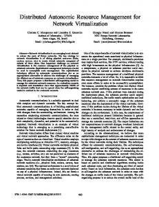
In our proposed MAS, the scale factor k should be considered as the number of P and M agents in the network, which is identical to the number of network nodes and the number of LPs respectively. It is also necessary to evaluate the function F with different network sizes and different numbers of LPs. For this purpose we have defined the networks proposed in Figure 7. Note that the scalability factor k is proposed to be the length of the side of the squared network.
k=3
k=6
k=9 Edge Nodes Core Nodes
Figure 7. Networks for the Scalability Evaluation.
where each network has the following properties: •
number of nodes
n = k2
•
number of edge nodes
e = 4*k-4
•
number of unidirectional LPs
nLP = e·(e-1)
(this is because we suppose that the edge nodes constitute a full meshed logical network) •
mean length (number of hops) of the LPs:
lLP = (4k2-8k-4) / (e-1)
(the addition of all the lengths of the LPs from one edge node – the origin – to all the other edge nodes, divided by the number of edge nodes except the origin edge node)
The scalability of the MAS basically depends on the amount of processing to be done by each P agent. This mainly depends on the management traffic due to the action of the P agents performing bandwidth readjustments and LP rerouting, and the number of P agents involved. The possible effect due to network failures is considered not to be significant in this study and is omitted. We are also omitting the weight due to the number of M agents in the edge nodes,
because they are lightweight processes (threads), which perform simple calculations and they are not active most of the time (this depends on the monitoring period).
Note that all the constant values used in the following definitions are derived from our experience in the implementation and simulation of the proposed MAS. In addition, it is worth saying that the behaviour of the resulting mathematical model mainly depends on the variable values.
The function C represents the amount of management traffic processed by each P agent, and is defined as:
C=
network number of partial view size · messages [number of nodes ]
=
M · nLP ·α · ∑ (CBPLP · OCLP ) LP
n2
(3)
where M represents the size (bytes) of the representation of a single LP (this depends on the mean LP length plus a fix part), and it is defined as M = 10 + 2·lLP. The partial network view that a P agent has is defined here as the knowledge of the P agent about the LPs that traverse the node it manages. Therefore, the factor M · nLP/n in Formula 3 is the size of the representation of a partial network view, and it is equal to the size of a management message containing a partial network view.
The remaining factors of the numerator
α · ∑ (CBPLP · OCLP ) LP
represent the number of
management messages, where α represents the number of messages needed to solve one congestion situation, CBPLP is the connection blocking probability for each LP, and OCLP is the offered connections for each LP. This model considers that all the connection rejections provoke congestion detection and, therefore, a bandwidth readjustment.
The term α depends on the algorithms used for solving a congestion situation. It is supposed that the MAS uses a bandwidth reallocation algorithm (which can decrease the underused bandwidth of an LP and use it to increase a congested LP) combined with the re-routing mechanism (a congested LP can be rerouted through a path where its assigned bandwidth can be increased). Analysing the simulation results, the possible situations are divided into three groups (probabilities p1, p2 and p3). In group 1, it is supposed that the congestion situation is solved using available bandwidth from the physical links and only 2 messages are used. In group 2, it is supposed that the congestion situation is solved by using underused bandwidth from another LP. In this case, it is also considered that all the LPs going through a node are checked. Therefore the number of messages generated depends on the number of LPs. It is supposed that these LPs are uniformly distributed throughout the network and that every P agent must check nLP/n LPs. In the third group, it is supposed that an LP re-routing is needed and that the messages used in the re-routing procedure are proportional to the mean LP length (lLP). Therefore α is defined as follows:
α = 2· p1 +
nLP · p2 + lLP· p3 n
(4)
The function λ represents the total amount of dispatched connections, and it is defined as:
λ = ∑ (OCLP · (1 − CBPLP )) LP
(5)
The function QoS represents the time spent in solving a congestion situation compared with a target time t0. It is similar to the function QoS defined in [18]. However, it is not realistic to expect the same response time in a small network as in a large network, because this is not an on-line service that requires the fastest response time possible in all situations, neither is it a
real-time mechanism. Therefore, we considered that the target time is acceptable if the congestion situation is solved in a time limit depending on the LP length. We have defined the target time as a function of the mean LP length t0 = 3 · lLP. The function QoS is defined as:
QoS =
1 3 = α · lLP 3 + α 1+ t0
(6)
Therefore the function QoS just depends on the difficulty (number of messages used) of solving a congestion problem. In order to simplify the model it is supposed that the CBPLP and OCLP are the same for all the LPs (CBP and OC). In this case, the functions C, λ, and QoS can be expressed as:
M · nLP 2 · α · CBP · OC C= n2
(7)
λ = nLP · OC · (1 − CBP) QoS =
3 3 +α
(8)
(9)
After the definition of the three functions, their combination using function F results, after simplification, in the following expression:
F=
λ C
QoS =
3n 2 · (1 − CBP) M · nLP · α · CBP · (3 + α )
(10)
Function F depends on the scalability factor k: F(k). However, as stated in [18] the scalability of a system should be evaluated comparing different scales of the system (Formula 1). Therefore,
function F is calculated for different scale factors k starting from k=10 and every one of them is compared with this initial value of F for k=10. The results are shown in Figure 8.
2,5 2 1,5
Ψ 1 0,5 0 0
50
100
150
200
250
k Figure 8. Scalability Evaluation.
The results obtained from the proposed mathematical model show that the MAS is not scalable (i.e. when k → ∞ then Ψ → 0), although it shows a suitable scalability using a wide range of scale factor k. This is because the model has a tendency to be very slow when approaching the zero value. This means that the system operation is fine with large networks (e.g. when k=100, there are 10000 nodes and 156420 LPs in the network), however, it seems reasonable that several design improvements could help in the achievement of better scalability. For instance, to reduce the number of transmissions of the partial network view and increase the autonomy of the P agents when making their decisions. It could also be interesting to study if it is possible to define a mechanism that allows the transmission of only the updated information from the last message between two P agents, and not the whole partial network view.
4.- Conclusions This paper has introduced the architecture of a Multi-Agent System devoted to dynamic network resource management by means of a logical network. This system integrates three functions (load balancing, fault restoration and spare capacity management) and carries out its
tasks in a complete distributed way. Therefore, the MAS agents are distributed over the network and there is a need for co-ordinating their actions. Moreover, none of the MAS agents have a global view of the logical network being managed; therefore there is also a need for collaboration between them. An important issue in these kind of distributed systems is the scalability, and in order to evaluate the MAS scalability a mathematical model of the agents’ interactions and co-ordination messages has been proposed. Results form this mathematical model show that the proposed MAS has a suitable scalability over a wide range of network sizes.
5.- References [1] [2] [3] [4] [5] [6] [7] [8] [9] [10] [11] [12] [13] [14]
Ken-ichi Sato, Satoru Ohta, Ikuo Tokizawa, “Broad-Band ATM Network Architecture Based on Virtual Paths”, IEEE Transactions on Communications, vol 38 no 8, August 1990 Z. Dziong, Y. Xiong, L.G. Mason, “Virtual Network Concept and its applications for resource management in ATM based networks”, International IFIP/IEEE Conference on Broadband Communications, Chapman & Hall, 1996. Armitage G., “MPLS: The Magic Behind the Myths”, IEEE Communications Magazine, January 2000. X. Xiao, A. Hannan, B. Bailey, L.M. Ni, “Traffic Engineering with MPLS in the Internet”, IEEE Network Magazine, March 2000. Eric Mannie (Ed), “Generalized Multi-Protocol Label Switching Architecture”, Work in Progress - Internet Draft (http://www.ietf.org), May 2003. Banerjee A., Drake J., Lang J.P., Turner B. Kompella K., Rekhter Y., “Generalized Multiprotocol Label Switching: An Overview of Routing and Management Enhancements”, IEEE Communications Magazine, January 2001. E.D. Sykas, K.M. Vlakos, M.J. Hillyard, “Overview of ATM networks: functions and procedures”, Computer Communications, vol 14, no 10, December 1991 Othmar Kyas, “ATM networks”, International Thomson Computer Press, 1995, ISBN 185032-128-0 Pere Vilà, Josep L. Marzo, Antonio Bueno, “Automated Network Management Using a Hybrid Multi-Agent System”, In proceedings of Artificial Intelligence and Applications (AIA 2002), September 9-12, 2002. Málaga, Spain. ACTA Press. Friesen V.J., Harms J.J., Wong J.W., “Resource Management with Virtual Paths in ATM networks”, IEEE Network, vol 10 no 5, September/October 1996. Yahara T., Kawamura R., “Virtual Path self-healing scheme based on multi-reliability ATM network concept”, IEEE GLOBECOM’97, November 1997. Kawamura R., Ohta H., “Architectures for ATM Network Survivability and Their Field Deployment”, IEEE Communications Magazine, August 1999. V. Sharma, B. Crane, S. Makarn, K. Owens, C. Huang, F. Hellstrand, J. Weil, L. Anderson, B. Jarnoussi, B. Cain, S. Civanlar and A. Chiu, “Framework for MPLS-based recovery”, Internet Draft, July 2002. E. Calle, T. Jové, P. Vilà, J.L. Marzo, “A Dynamic Multilevel MPLS Protection Domain”, 3rd International Workshop on Design of Reliable Communication Networks, DRCN, Budapest (Hungary), 2001.
[15] Xiong Y., Mason L.G., “Restoration Strategies and Spare Capacity Requirements in SelfHealing ATM Networks”, IEEE/ACM Transactions on networking vol.7 no.1, February 1999. [16] T.H. Oh, T.M. Chen, J.L. Kennington, “Fault Restoration and Spare Capacity Allocation with QoS Constraints for MPLS Networks”, GLOBECOM 2000. [17] Kyu Seek Sohn, Dan Keun Sung, “A Distributed LPS Mechanism to Reduce Spare Bandwidth in MPLS Networks”, ICC 2002. [18] P. Jogalekar and M. Woodside, “Evaluating the scalability of Distributed Systems”, Proc. 31st Annual Hawaii International Conference on System Sciences, IEEE Computer Society Press, vol. 7 (January 1998), pp. 524-531. [19] A-L. Burness, R. Titmuss, C. Lebre, K. Brown, A. Brookland, “Scalability evaluation of a distributed agent system”, Distributed Systems Engineering 6, The British Computer Society, IEE and IOP Publishing Ltd., 1999. [20] P. Jardin, “Supporting Scalability and Flexibility in a Distributed Management Platform”, Distributed Systems Engineering 3, The British Computer Society, IEE and IOP Publishing Ltd., 1996. [21] L.C. Lee, H.S. Nwana, D.T. Ndumu, P. De Wilde, “The stability, scalability and performance of multiagent systems”, BT Technology Journal, vol. 16 no. 3 (July 1998). [22] P. Jogalekar and M. Woodside, “Evaluating the scalability of Distributed Systems”, IEEE Transactions on Parallel and Distributed Systems, vol. 11, no. 6 (June 2000), pp. 589-603. [23] C. Bohoris, G. Pavlou, H. Cruickshank, “Using mobile agents for network performance management”, Network Operations and Management Symposium (NOMS). 10-14 April 2000. [24] Pere Vilà, José L. Marzo, Eusebi Calle, “Dynamic Bandwidth Management as part of an Integrated Network Management System based on Distributed Agents”, In Proceedings of IEEE Global Communications Conference (GLOBECOM), Taipei (Taiwan), November 17-21, 2002. [25] J.L. Marzo, P. Vilà, L. Fàbrega, D. Massaguer, “A Distributed Simulator for Network Resource Management Investigation”, Computer Communications Journal (Elsevier) 26 pp. 1782-1791, September 2003.