Proceedings of DETC/CIE’06: 2006 ASME International Design Engineering Technical Conferences & Computers and Information In Engineering Conference Philadelphia, Pennsylvania, September 10-13, 2006
DISTRIBUTED REAL-TIME VEHICLE VALIDATION Mikael Nybacka Division of Computer Aided Design Department of Mechanical Engineering Luleå University of Technology SE-971 87 Luleå, Sweden E-mail:
[email protected]
Peter Törlind Division of Computer Aided Design Department of Mechanical Engineering Luleå University of Technology SE-971 87 Luleå, Sweden E-mail:
[email protected]
Tobias Larsson Division of Computer Aided Design Department of Mechanical Engineering Luleå University of Technology SE-971 87 Luleå, Sweden E-mail:
[email protected]
Mathias Johanson Alkit Communications AB Sallarängsbacken 2 SE-431 37 Mölndal, Sweden E-mail:
[email protected]
Keywords: Real-Time simulation, Multi-Body Dynamics, Validation, Distributed Collaborative Engineering. ABSTRACT Due to the increasing complexity of embedded systems and software in vehicles, the automotive industry faces an increasing need for testing and verification of components and subsystems under realistic conditions. At the same time, development cycles must be shortened in order for vehicle manufacturers to be competitive on the global market. Consequently, an increased amount of testing and verification must be performed in less time. However, simply increasing the volume of the testing can be prohibitively costly, implying that the testing and verification processes must be made more efficient, reducing the need for more prototypes. This paper presents a concept for distributed testing and verification of vehicles in real time, with the aim of improving the efficiency of testing and verification. Through a novel combination of software tools for distributed collaborative engineering, real-time simulation, visualization, and black box simulation, a system is realised that makes it possible for vehicle manufacturers and their subcontractors to work more concurrently and efficiently with testing and validation. An early prototype implementation of the system is decribed, and future developement plans for the system is presented. The main software components that the system is built upon are ADAMS/Car RealTime, Matlab/Simulink and a Java-based real-time visualization module, originally developed for the gaming industry. One of the main benefits of the concept is that different disciplines involved in the product development process can use the system to enhance the concurrency between them. Control systems and mechanical engineers can view ongoing tests in real time and change designs, re-simulate and influence ongoing tests in a distributed and efficient way. Through advanced visualization of simulation results and measurement data, the engineers can get a clearer view on how the system or product behaves, improving the quality of the validation process.
The concept for distributed real-time simulation and visualization described in this paper will gather more information in the early stages of product development. Furthermore, it will speed up the product development process due to its real-time nature. The fact that engineers can stay at their home office and only follow the test when it is needed will enhance their efficiency. INTRODUCTION A clear trend in the automotive industry is that the manufacturers outsource more development work to subcontractors. Consequently, the overall quality of the finished product will depend on how well the automotive companies and the subcontractors work together in the development processes. Lack of harmonization between the subcontractors and the automotive company – but also between different development departments at the manufacturer – causes expensive errors. Therefore, methods and tools have to be developed to support the whole development process and these have to be easy to work with, in order to be applicable [1, 2]. The need for validation of vehicles has been increasing during the resent years, mainly due to the increasingly complex electronic control systems developed for the vehicles. A lot of time is to validation, in order to manufacture reliable and safe systems. To quote Professor Alberto Sangiovanni Vincentelli [3], “It is no wonder that more than 30% of severe malfunctions in automobiles are originated by faulty software. We need a new system science to deal with the digital abstraction and the physical world in a unified way.” This paper suggests methods and tools for reducing leadtimes in the validation phases of product development (PD). It also exemplifies how we can cope with the digital abstraction and the physical world.
1
Copyright © 2006 by ASME
Today’s automotive companies must be able to cope with distributed product development, due to the many suppliers involved in the development of vehicles. Dannenberg [1] estimates that there are around 5000 suppliers to the automotive industry today. Since suppliers and subcontractors from all over the world frequently need to be involved in the testing and verification of the vehicles, it is necessary to develop sophisticated methods and tools for distributed validation and simulation, and to incorporate these tools and methods into the overall framework for distributed product development. The idea with the distributed real-time simulation and visualization (DRTSV) concept is to extend the testing and verification processes, from the test tracks to the manufacturer's and subcontractors' development offices. This will result in more effective test expeditions and shorter development time. Furthermore, connecting mechanical and/or control system modules to the DRTSV concept in a black box fashion, as suggested by Larsson et al. [8], will give the manufacturer and subcontractors a good development tool for the PD process. Using a wireless local area network (WLAN) at the test tracks, live measurement data can be sent from the vehicles at the test track back to the development site of the manufacturer, for analysis and visualization, in real-time if desired. Having the possibility to share and view data in real-time from the test track will reduce costs and lead-times significantly for vehicle manufacturers. Törlind [7] describes a technlogical framework by means of which car manufacturers and suppliers in the northern region of Sweden have the possibility of transmitting data in real-time from test vehicles to the development facilities all over the world. By integration of this framework with the systme presented here, live measurement data can be used as input for hardware-in-the-loop simulation and real-time visualization, giving the opportunity to study effects not directly measurable, such as the normal forces on the tires of a moving car. Our vision is that in the future automotive test engineers will be able to take part in vehicle testing without having to be physically present at the test track, and still being as involved in the tests as if they were there. To achieve this, measurement data must be transmitted in real time to the development site, where it can be analysed and visualized. Moreover, interpersonal communication and data exchange between the local and remote engineers must be flexible and effortless. As an illustration of the vison, consider a case where the engineers want to study the influence of the suspension module on the braking performance on ice. Using our approach, they can do so by feeding live measument data (acceleration, position, speed) into a dynamic simulation module that calculates the normal forces on the tires. The normal forces can be visualized in real time in a virtual reality system, for instance as dynamically changing graphical vectors. Going one step further, one part of the suspension simulation system can be located at a subcontractor, using a black box simulation approach to protect the simulation model. The dynamic simulation forces on the suspension module is transmitted to the subcontractor, and tire
forces are returned. All information from the simulation module can be combined with measured data from the car on the test track and visualized in a shared visualization system, or presented as curves. Imagine if any test can be performed by sending measurement data directly to an expert’s office, where it is visualized and analyzed in real-time. The expert can follow the ongoing test through a virtual reality 3D visualization of the vehicle, and also via video from the vehicle. If the expert can speak to the test driver through an audio link, he can influence the ongoing test to better suit his needs. There is also a possibility for the remote expert to download new software to the vehicle directly through the wireless communication link. Working in this manner will reduce the overall test time which gives room for even more tests. All of the engineers from the home office no longer have to travel to the test expedition; they can follow the expedition from their office workplace and let local entrepreneurs perform the tests for them. This will save the automotive manufacturers and suppliers a lot of time and money.
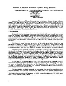
Figure 1. Real-Time simulation with hardware in the loop and black box simulation. By using a dynamic simulation system to simulate the behavior of the vehicle, it will be possible to access data that is hard or even impossible to measure, for instance force between tire and road and forces in joints, etc. The visualization module can be set up to present data that is interesting to many disciplines at the same time, e.g. climate, fatigue, control systems, vibration analysis, etc. RELATED WORK AND BACKGROUND The work presented in this paper builds on previous work at the division of Computer Aided Design at Luleå University of Technology concerning distributed collaborative engineering (DCE), distributed automotive winter testing and multibody simulation of vehicles. Larsson et al. [8] presents a system for web based simulation where only a web browser is needed - and the user can work anywhere in the world in a thin client fashion. The
2
Copyright © 2006 by ASME
most evident advantage is the possibility of distributing simulation modules, or whole simulation models, from simulation experts to design experts and engineers. The distributed approach allows cooperative companies to protect company specific knowledge by distributing simulation modules of models or complete systems in a black box fashion, were some parameters are available for modification, while the company sensitive parameters and structures are protected. By extending this approach in a modular approach [9], sub models can be distributed though the network. By combining the above mentioned technologies with existing technologies for remote collection of telemetric data from test objects [7], distributed simulation can be combined with hardware-in-the-loop simulations. Through the integration of these technologies, new possibilities for merging simulation with hardware can be achieved. Previous work by Törlind et al. [7] concerns climate testing with static visualization modules, but this can be generalized to virtually any kind of testing scenario, and integrated into the new dynamic visualization module. THE DISTRIBUTED REAL-TIME VEHICLE VALIDATION CONCEPT Combining distributed collaborative engineering, real-time simulation and visualization together with black box simulation will give vehicle manufacturers and their suppliers a very powerful PD tool. One of the main benefits of the concept is that different disciplines involved in the product development process can use the system to enhance the concurrency between them. Control system engineers and mechanical engineers can view ongoing tests in real time and change designs, re-simulate and influence ongoing tests in a distributed and efficient way. Through advanced visualization of simulation results and measurement data, the engineers can get a clearer view on how the system or product behaves, improving the quality of the validation process. Presented in this paper is an early prototype of a software framework for distributed real-time vehicle validation. The framework is largely based on well-know software components in use in the automotive industry today, which facilitates implementation of the concept in industry. The prototype consists of input, data management, simulation and visualization components, as illustrated in Figure 2. The components have the following functionality: •
•
The input components is currently a joystick; this will later be exchanged for a measurement data input component from an actual car. It sends steering, throttle and brake signals to the data management block. The data management block consists of a Matlab/Simulink component, that receives data from the input component, performs some necessary
•
•
preprocessing, and sends it over a network link to the simulation component. The simulation block is an ADAMS/Car RealTime component that computes the behavior of the car based on a given input and a simulation model. The result is sent back to the data management component, that processes the data and transmits it over a network link to the visualization module. The visualization component receives data such as position, velocity, forces, etc, and uses this data in combination with a 3D model of the car, for 3D visualization of the car's behavior in a virtual environment.
Figure 2. Early prototype system of real-time simulation and visualization. Product Development Process The following section describe how the DRTSV concept can be used in the PD process. As previously noted, future vehicle testing processes need to be faster and more effective, to be able to test all the new control systems on vehicles. These control systems will increase in numbers and complexity in the future, which implies that the methods for testing vehicles and their control systems need to be enhanced considerably to decrease the time spent on testing [7]. One way to achieve this is to make use of wireless technology at the test facilities to perform concurrent validation from remote locations. What this means is that an engineer at the development office for automotive systems can concurrently work with one subsystem of the vehicle, while a test expedition is conducted concerning some other subsystem of the vehicle. Input data to a simulation model can thus be received, in realtime, from a car at an ongoing test expedition. In the meantime, a software engineer can work with a different subsystem and receive data from the same test expedition. From the 3D visualization of the car, and from live video transmissions, they can monitor how their systems
3
Copyright © 2006 by ASME
perform. If they notice any abnormal behavior they can change their system and upload software upgrades to the ECUs in the vehicle. With the possibility of communicating with the test driver through an audio (and video) link they can get valuable information about how their systems perform, and change them directly if necessary. Saving the input data from the test expedition into a file format that the simulator can read (e.g. in ADAMS/Car typically a driver control file, DCF), will give the possibility to simulate problems that arise in more detail after the test is fnished. By saving logged data from the car together with the DCF, the engineers can reproduce the problem and make changes to the software or the design. The concept will be useful for hardware-in-the-loop, software-in-the-loop and real-time validation during test expeditions. It is possible to use the system from early product development to validation of preproduction systems at the test expeditions (see Figure 3). Visualization Using a dynamics simulator such as ADAMS/Car RealTime makes it possible to produce test data that is hard or even impossible to measure, e.g. tire, chassis forces. By using a 3D engine originally developed for the gaming industry, we get the possibility of building synthetic environments that resemble the reality very well. Visualiziation in real-time demands high graphics performance, which calls for different 3D graphics engines compared to what CAE tools have to offer. This is the reason why visualization tools from the gaming industry – which today is the technological vanguard of 3D visualization – are interesting to use for this application. With the use of Global Positioning System (GPS) and maps it is possible to model the whole test track with trees, buildings, sunlight, shadows, etc. Modeling the sunlight and its direction can be useful not only for added visual realism, but also to provide information for instance about why the temperature suddenly increased in the coupe at a climate tests. Another example of why you want highly realistic graphics is to be able to keep good track of the environment where the vehicle is during the test. Adding special features to the real-time visualization model will give the beholder a better and more logical overview. Vector force and moment graphics will be of use when monitoring the behavior of the dynamic control systems. Vectors visualizing the normal forces on the tires give a lot of information about how the vehicle behaves. Changing colors of parts when special events occur, e.g. when systems fail or when the brakes lock the wheels gives a clear an prompt notification to the user. When the visualization model consists of many parts there will useful with a function for showing/hiding parts during simulation. Using a cutting plane through the model will also enhance the view ability of the model. Moreover, it will give the possibility of visualizing temperature, vibration and sound fields in the model. This can be represented with color gradients in the cutting plane of the model.
Being able to save simulations in the visualization module gives the engineer a better view of how the new system will work. Consider that you have saved the last simulation and you modify the system to run a new simulation with the saved simulation as a reference. This will give the engineer a direct visual confirmation of how the system behaved in a particular situation. Implementation in industry There are numerous areas in the PD process where the DRTSV concept will be of befit (see Figure 3). When considering black box simulation together with DRTSV, it is applicable on development of early control systems solutions and all the way up to preproduction control systems. Firstly we have the prototype system development. During development, data from the actual testing can be used for simulating the behavior of the vehicle. The systems can be tested for early bugs and misbehaviors. Secondly, specified systems can be tuned in using the virtual simulation of the vehicle. Thirdly, systems for preproduction vehicles can be tuned concurrently during test expeditions. Another area of implementation would be the distributed visualization and simulation to the suppliers. Also, the mechanical engineers have good use of DRTSV, especially since the mechanical systems have to function well with the electronic systems and software. The use of the same tool suite and methods will harmonize the work of the electronic and mechanical engineers in the automotive industry [2].
Figure 3. Potential use of DRTSV RESULTS The preliminary result of this work is an early prototype system based on a combination of software tools, some of which are already used in the automotive industry. The prototype system is mainly based on ADAMS/Car RealTime, Matlab/Simulink and a Java-based 3D visualization module called AgentFX.
4
Copyright © 2006 by ASME
Prototype system A schematic model of the prototype system can be seen in Figure 2. Input to this system is a joystick that later will be replaced by a measurement collection and transmission unit installed in an actual car, in this case a formula SAE car built by students at Luleå University of Technology. The formula car was chosen instead of a production vehicle for the ability to perform tests of the system at a quicker pace and with better control of the whole system. Data management and communication Matlab/Simulink is used as the communication interface between ADAMS/Car RealTime, the visualization tool AgentFX™ and the real-time data input from the joystick. The Simulink model collects input data to the real-time model from the joystick (throttle, brake and steering), which represents the data that will be collected from a car in future research. Simulink passes the data on to ADAMS solver for dynamic calculations, which then passes the results back to the Simulink model, that packetizes the data needed for visualization into units suitable for network communication, and sends it to the visualization tool AgentFX™ [5].
give an effective tool for solving complex and multidisciplinary problems. The formula SAE car has been modeled in ADAMS/Car and exported to ADAMS/Car RealTime. The ADAMS/Car model has 71 degrees of freedom (DOF) and the Real-Time model have 16 DOF. The ADAMS/Car RealTime model does not have linkages or bushings, and the steering system does not have parts for the steering wheel or rack. Instead, the model requires input parameters from, e.g. Kinematics and Compliance (K&C) test machine or data virtually obtained from ADAMS/Car simulations. This makes it possible to run the simulation faster than real-time [4]. Visualization AgentFX™ is an advanced toolkit for developing interactive 3D applications and objects in real time. AgentFX™ is based on Java and uses the OpenGL Application Programming Interface (API). AgentFX™ allows software development for a wide range of platforms, eliminating the need to rewrite code for different platforms. Applications are immediately ready for use on platforms such as Microsoft Windows, Apple Mac OS X, Web environments, handheld units using Pocket PC or similar, Linux and UNIX workstations such as SUN Sparc, and more.
Figure 4. Visualization module with applied textures. The advantages of using this kind of software is high graphical performance and applicability in heterogeneous computing environments, since the visualization module can be executed from any computer with a Java virtual machine installed. Figure 4. Matlab/Simulink model. Simulation For the last twenty years, automotive manufacturers have used multi-body simulation tools in the virtual product development (VPD). This is to understand how the product will perform, but also to understand different phenomena that can arise. Using MBS together with other software components will
CONCLUSIONS AND FUTURE WORK Future work consists of replacing the joystick-based input module of the prototype system with a measurement data collection and communication unit installed in the formula SAE car. Real tests at a local winter test facility will be performed to validate the functionality, bandwidth requirements, and how near real-time the system can work. Also, further work on the
5
Copyright © 2006 by ASME
visualization model of the car and the virtual environment will be preformed, for enhanced realism. Investigations will be undertaken regarding whether Matlab/Simulink and ADAMS/Car RealTime can be used for other purposes than explored in this paper. Questions concerning data acquisition will be worked upon in parallel with another research projects. During the PD process it is crucial to gather as much information as possible about the product. This information will help eliminating flaws for the next generation of the product. The concept for distributed real-time vehichle validation described in this paper will facilitate the collecion of data in the early product development stages. Moreover, it will speed up the product development process due to its real-time nature, promoting instant analysis of measurement and simulation data. The fact that high competence engineers to a larger extent can remain at their home office and still take part in remote testing expeditions, will increase thier productivity when it is needed will enhance their efficiency.
8.
Larsson, T., Larsson, A., Karlsson, L., 2001, Distributed Multibody Dynamic Analysis Within Product Development, Proceedings of the DETC’01 ASME 2001 Design Engineering Technical Conferences and Computers and Information in Engineering Conference Pittsburgh, Pennsylvania, September 9-12.
9
Larsson, T. and Larsson, A. Web-based Multibody Dynamics using Distributed Simulation Modules, Annals of 2002 Int’l CIRP Design Seminar, 16-18 May 2002 in Hong Kong
10 Törlind, P., Larsson, A., Löfstrand, M., Karlsson, L., Towards True Collaboration in Global Design Teams. In Proceedings of 15th International Conference on Engineering Design, ICED 05, August 15-18 2005, Melbourne, Australia.
ACKNOWLEDGMENTS Funding from Norrbottens Forskningsråd and the successful workshops with Agency9 AB are greatly acknowledged. REFERENCES 1. Dannenberg. J, K.C., The Coming Age of Collaboration in the Automotive Industry. Mercer Management Journal, 2004. 2.
Grimm, K. Software Technology in an Automotive Company - Major Challenges. In Proceedings of the 25th International Conference on Software Engineering (ICSE'03). 2003. Portland. Oregon.
3.
Schäuffele. J, Z.T., Automotive Software Engineering. 2005, Warrendale: SAE International.
4.
MSC.Software. [cited 2005; Available from: http://www.mscsoftware.com.
5.
MathWorks. [cited 2005; http://www.mathworks.com/.
6.
Giusto. P, D.T., Rapid design exploration of saftycritical distributed automotive applications via virtual integration platforms. The Journal of Systems and Software, 2004: p. 245-262.
7.
Törlind, P., A Collaborative Framework for Distributed Winter Testing. In proceedings of eChallenges e-2004. October 2004: Vienna, Austria.
Available
from:
6
Copyright © 2006 by ASME