their internal dynamics, hence protecting the proprietary information (Byam and. Radcliffe 1999 ...... was discovered by William Grove in 1839. Although it was ...
DISTRIBUTED ROUTINE DESIGN OVER THE INTERNET WITH COOPERATING MDM AGENTS By Mustafa Taner Eskil
A DISSERTATION Submitted to Michigan State University in partial fulfillment of the requirements for the degree of DOCTOR OF PHILOSOPHY Computer Science and Engineering 2004
ABSTRACT DISTRIBUTED ROUTINE DESIGN OVER THE INTERNET WITH COOPERATING MDM AGENTS By Mustafa Taner Eskil
The availability of reliable, high-speed electronic connectivity enabled collaborative design teams function irrespective of physical distance. But the advent of the Internet has not as yet given rise to a simulation environment that leverages the inherent advantages offered while observing basic constraints imposed by the current wired world, most notably practical limitations on the amount of network traffic. The changes in the procurement process of enterprises need to be reflected in a new type of design and simulation environment – one that facilitates automated searching and locating of satisfying and optimizing parts, integration of selected parts in an assembly, and simulation of the overall design that is distributed over the Internet.
Our goal is to develop an automated and distributed scheme for design and simulation of engineering artifacts, in the context of open and competitive e-commerce. With the realization of our goal, designers will be able to automatically incorporate distributed offthe-shelf parts into their designs, simulate them as integrated components of the end product, and make their final designs available to prospective buyers without disclosing proprietary information.
In this dissertation we describe a conceptual framework and implementation that supports task directed, distributed Multiple Routine Design augmented with simulation-based design testing. In our research, we leverage the Modular Distributed Modeling (MDM) methodology to simulate the interaction of design components in a distributed assembly. The major extension we have made to the overall methodology of Routine Design is to extend it with the capabilities of incorporating remotely represented off-the-shelf components in design and simulation based testing of a distributed assembly. The deliverable of our research is a conceptual framework and implementation of a distributed multiple routine design platform (RD-MDM) that is capable of automated multi-attribute search for remotely represented off-the-shelf design components, design parameterization by choosing suitable components for the design, integrating these components in an assembly, running simulations for testing the total design, and publishing the approved design as an MDM agent.
For KAPI, my brother
iv
ACKNOWLEDGEMENTS
I would like to thank my advisor, Dr. Jon Sticklen, for his persistence in presenting me with challenges throughout my research. I owe my significant growth not only as a researcher but also as an educator to his high standards, equally challenging expectations, and most importantly his continuous trust in me. I was lucky to get to know and work with a brilliant researcher, an ambitious instructor, and a compassionate, caring person over the last five years. The completion of this dissertation has been possible only with his guidance and support.
Dr. Clark Radcliffe provided valuable insight and support throughout the course of this research. I am thankful to him for welcoming me in his laboratory in the Mechanical Engineering Department and providing me the space and network for computer servers, which were critical for this research. I would also like to thank Dr. Roger Calantone, who broadened my perspective with his vast industry knowledge and business management expertise and had significant influence in my research and this dissertation.
As always I am grateful to my parents, Hasan and Emine Eskil, who always put us first, showed unconditional love, and provided never-ending support. I would not be anywhere near I am now if it were not to their loving care.
I am eternally grateful to have my beloved, Fezal Okur in my life, who has always inspired and challenged me, and stood next to me in my best times and worst. v
TABLE OF CONTENTS
LIST OF TABLES ......................................................................................... x LIST OF FIGURES .................................................................................... xii LIST OF ABBREVIATIONS ...................................................................xiv
I
Prelude
1
CHAPTER 1 INTRODUCTION 1.1. 1.2. 1.3. 1.4. 1.5. 1.6. 1.7.
II
2
The Process of Engineering Design ..................................................... 2 Design Knowledge ........................................................................... 4 Agility ............................................................................................ 9 Managing Distributed Information .................................................... 11 Simulation of Distributed Subassemblies ....................................................14 Internet Applications for Collaboration in Design ................................ 15 Goals and Strategies......................................................................... 17
Previous Research
22
CHAPTER 2 ONLINE COLLABORATION TECHNIQUES
23
2.1. DIMS for Internet Based Design ..................................................................24 2.2. Electronic Product Catalogues .....................................................................30 2.3. Systems that Protect Intellectual Property ...................................................32
CHAPTER 3 GENERIC TASK – ROUTINE DESIGN 3.1. 3.2. 3.3. 3.4. 3.5.
34
The Routine Design Process ........................................................................36 The GT Approach to the Engineering Design Process.................................37 Routine Design Using the GT Approach .....................................................40 Procedure of GT-RD ....................................................................................41 Types of Knowledge and Control Strategies in RD .....................................43 vi
CHAPTER 4 MODULAR DISTRIBUTED MODELING 4.1. 4.2. 4.3. 4.4.
III
45
Object Oriented Engineering ........................................................................46 The Agent Technology .................................................................................47 Multi-Agent Systems....................................................................................49 The MDM Methodology ..............................................................................50 4.4.1. Functional Response Modeling......................................................52 4.4.2. Deriving FRMs for Assemblies .....................................................56 4.4.3. MDM for Simulation of Distributed Assemblies...........................60
RD-MDM
62
CHAPTER 5 PROBLEM STATEMENT AND RESEARCH MILESTONES
63
5.1. Problem Statement .......................................................................................64 5.2. Synergy of RD and MDM Methodologies ...................................................66 5.3. Research Milestones .....................................................................................68
CHAPTER 6 THE MDM FRAMEWORK
69
6.1. Characteristics of an MDM Agent ...............................................................69 6.2. The MDM Architecture ................................................................................73 6.3. Protection of Proprietary Information ..........................................................75
CHAPTER 7 EXTENDING GT-RD TO DISTRIBUTED MODELING
78
7.1. MDM Agent Selection Task ........................................................................79 7.2. Incorporating MDM Agents into Design .....................................................81
CHAPTER 8 USER INTERACTION WITH RD-MDM
84
8.1. MDM Agent Browsing.................................................................................84 8.2. MDM Agent Design .....................................................................................85 8.3. RD-MDM Designer......................................................................................88
vii
IV
Distributed Routine Design of Fuel Cell And Hybrid Vehicles with RD-MDM
CHAPTER 9 FRMs OF DRIVE TRAIN COMPONENTS
89
90
9.1. Hybrid Vehicles............................................................................................92 9.2. Fuel Cells......................................................................................................93 9.2.1. Open Circuit Voltage .....................................................................97 9.2.2. Activation Loss ..............................................................................98 9.2.3. Concentration Loss ........................................................................99 9.2.4. Ohmic Loss ....................................................................................99 9.2.5. Closed-Circuit Voltage ................................................................100 9.3. Electric Motors ...........................................................................................103 9.4. Transmissions .............................................................................................105 9.5. Vehicle Mass and Acceleration ..................................................................106
CHAPTER 10 FUEL CELL AND HYBRID VEHICLE DESIGN 10.1 10.2 10.3 10.4 10.5
108
Assembling the Electric Motor and the Drive Train ..................................109 Assembling the Fuel Cell Vehicle ..............................................................113 Modeling Hybrid Vehicles .........................................................................117 Assumptions ...............................................................................................119 Setting Up the Routine Designer ................................................................119 10.5.1 Fuel Cell Vehicle Design .............................................................127 10.5.2 Fuel Cell/Battery Hybrid Vehicle Design ....................................135 10.5.3 Multiple Distributed Routine Design of a Hybrid Vehicle ..........144
CHAPTER 11 CONCLUSIONS
146
11.1 Experimental Results..................................................................................146 11.2 Distributed Problem Solving: A Comparative Study .................................148 11.2.1 Step 1 – Decomposing the Problem and Setting up Problem Solvers..........................................................................................151 11.2.2 Step 2 – The Design Process ........................................................153 11.2.3 Step 3 – Design Testing ...............................................................156
viii
V
Summary and Conclusions
CHAPTER 12 SUMMARY AND CONCLUSIONS 12.1 12.2 12.3 12.4 12.5 12.6
159
160
Motivation ..................................................................................................161 Research Goals ...........................................................................................164 Approach ....................................................................................................165 Results ........................................................................................................168 Contributions ..............................................................................................170 Future Directions ........................................................................................175
APPENDIX A. MDM COMPONENTS .................................................. 179 APPENDIX B. GRAPHS FOR CITY DRIVING CONDITIONS ........ 193 APPENDIX C. FUTURE WORK ......................................................................196 BIBLIOGRAPHY ...................................................................................... 200
ix
LIST OF TABLES
Table 10.1 – High EM Torque Plan Sponsor ..................................................................121 Table 10.2 – Selection of an EM .....................................................................................122 Table 10.3 – Selection of an EM Plan .............................................................................128 Table 10.4 – Selection of an EM .....................................................................................128 Table 10.5 – Selection of a Transmission Plan ................................................................129 Table 10.6 – Selection of a Transmission ........................................................................129 Table 10.7 – Selection of an FC Plan ..............................................................................130 Table 10.8 – Selection of a Fuel Cell ...............................................................................130 Table 10.9 – Fuel Cell Vehicle Design and Simulation Results ......................................135 Table 10.10 – Hybrid Vehicle Design and Simulation Results .......................................141 Table 10.11 – Comparison of Results for the Fuel Cell and Hybrid Vehicle ..................142 Table 10.12 – Merit Table for Hybrid Vehicle Design Alternatives ...............................144 Table A.1 – Agent Registry MDM Agent .......................................................................179 Table A.2 – Query Ontology MDM Agent ......................................................................179 Table A.3 – Fonyun 54533 Lead-Acid Automotive Battery ...........................................180 Table A.4 – Fonyun 57412 Lead-Acid Automotive Battery ...........................................180 Table A.5 – Fonyun N100Z Lead-Acid Automotive Battery ..........................................181 Table A.6 – Fonyun NS60 Lead-Acid Automotive Battery ............................................181 Table A.7 – Sealake 56638 Lead-Acid Automotive Battery ...........................................182 Table A.8 – Haiju 55530 Lead-Acid Automotive Battery ...............................................182
x
Table A.9 – Siemens 1PV5105 WS12 Electric Motor ....................................................183 Table A.10 – Siemens 1PV5133 WS18 Electric Motor ..................................................184 Table A.11 – Siemens 1PV5135 WS14 Electric Motor ..................................................185 Table A.12 – Siemens ACW-80-4 Electric Motor...........................................................186 Table A.13 – Hydro Power 1.05-0.013 Fuel Cell ............................................................187 Table A.14 – Hydro Power 1.15-0.011 Fuel Cell ............................................................187 Table A.15 – Hydro Power 1.25-0.009 Fuel Cell ............................................................188 Table A.16 – Hydro Power 1.35-0.008 Fuel Cell ............................................................188 Table A.17 – Hydro Power 1.05-0.013 Fuel Cell Stack – 300, 400, 500 Series .............189 Table A.18 – Hydro Power 1.05-0.011 Fuel Cell Stack – 300, 400, 500 Series .............190 Table A.19 – Hydro Power 1.25-0.009 Fuel Cell Stack – 300, 400, 500 Series .............190 Table A.20 – Borg Warner 5000 Velvet Drive Automotive Transmission .....................191 Table A.21 – Borg Warner 72C Velvet Drive Automotive Transmission ......................191 Table A.22 – Borg Warner Velvet Drive Automotive Transmission ..............................192 Table A.23 – Hurth HSW-630V Automotive Transmission ...........................................192
xi
LIST OF FIGURES
Figure 1.1 – How Engineers Use the Internet ......................................................................7 Figure 3.1 – The Architecture of GT Routine Design .......................................................42 Figure 4.1 – Modular Modeling Element Graphical Notation ...........................................54 Figure 4.2 – Subsystem Model with Two Components.....................................................57 Figure 6.1 – Sketch of the Information Exchange Topology.............................................73 Figure 6.2 – Sketch of MDM Agent Community ..............................................................74 Figure 7.1 – Routine Design of an Automobile Using MDM Agents ...............................81 Figure 8.1 – RD-MDM Query Console .............................................................................85 Figure 8.2 – RD-MDM Agent Publisher ...........................................................................86 Figure 8.3 – RD-MDM Agent Editor ................................................................................87 Figure 9.1 – The Fuel Cell Stack .......................................................................................94 Figure 9.2 – Schematic of a PEM Hydrogen Fuel Cell .....................................................96 Figure 9.3 – Linearized Model for the Fuel Cell .............................................................101 Figure 9.4 – Circuit Analogy for the Fuel Cell ................................................................102 Figure 9.5 – Internal Model of an Electric Motor ............................................................103 Figure 9.6 – Transmission Diagram.................................................................................105 Figure 10.1 – The Routine Designer for Fuel Cell Vehicles ...........................................120 Figure 10.2 – Acceleration Simulation Using Component Modular Models ..................124 Figure 10.3 – Fuel Consumption Simulation Using Component Modular Models .........125 Figure 10.4 – Cost Calculation Using Component Costs ................................................126
xii
Figure 10.5 – The GT Calculator .....................................................................................127 Figure 10.6 – The Simulink Model for the Fuel Cell Vehicle .........................................132 Figure 10.7 – Fuel Cell Vehicle Acceleration and Maximum Speed ..............................133 Figure 10.8 – Fuel Cell Vehicle Speed in City Driving Conditions ................................134 Figure 10.9 – The Simulink Model for Hybrid Vehicle Simulation ................................139 Figure 10.10 – The Routine Designer for Hybrid Vehicles .............................................140 Figure 10.11 – Graphical Representation of Hybrid Vehicle Design Alternatives .........143 Figure 11.1 – The PACT Architecture .............................................................................149 Figure 11.2 – RD-MDM Robotic Arm Manipulator Designer ........................................154 Figure B.1 – Current Drawn by EM During City Driving Simulation ............................193 Figure B.2 – Battery Charge Level During City Driving Simulation ..............................194 Figure B.3 – Current Through FC During City Driving Simulation ...............................195 Figure B.4 – Current Through Battery During City Driving Simulation ........................195 Figure C.1 – The Battery Circuit Model ..........................................................................196
xiii
LIST OF ABBREVIATIONS
CAD
Computer Aided Design
CORBA
Common Object Request Broker Architecture
DCOM
Distributed Component Object Model
DIMS
Distributed Information Management Systems
DSPL
Design Specialists and Plans Language
EM
Electric Motor
EMF
Electromotive Force
FC
Fuel Cell
FRM
Functional Response Model
GT
Generic Task
i-EDA
Internet Engineering Design Agents
IIOP
Internet Inter-ORB Protocol
ISO
International Standards Organization
KBS
Knowledge Based Systems
MDM
Modular Distributed Modeling
MDSPL
Multiple Design Specialists and Plans Language
MRD
Multiple Routine Design
ORB
Object Request Broker
PACT
Palo Alto Collaborative Testbed
PEM
Proton Exchange Membrane
RD
Routine Design
STP
Standard Temperature and Pressure
TR
Transmission
xiv
Part I Prelude
1
CHAPTER 1 Introduction
1.1. The Process of Engineering Design A designer’s task in society is to improve the quality of life, through improved transportation, communication devices, household products, etc. Initially in the design process, what is considered better or improved is not crisply defined, and many times performance requirements will be cross-coupled. This introduces an inherent compromise between design alternatives and often results in multiple solutions to the design problem (Pugh 1991). Due to the lack of a well defined initial objective, the design process has been described as an ill-structured activity (Rowe 1987; Cross 1994) and one of the most demanding of all human activities (Gero 1990).
Typically the design process starts with a search for understanding the domain, constraints and requirements of the problem at hand. Depending on their backgrounds and related experience, different designers will almost certainly focus on different aspects of the problem, potentially reaching different design specifications (Jones 1970). This strong dependence of design on the individuals together with the ill-structured nature of design makes the design process as much an art form as a technical work style.
2
Engineering design of complex systems is often done by breaking the functionality of the overall system into simpler and sometimes existing subsystems and developing an assembly plan to bring these subsystems together. Particularly in the design of domestic consumer products such as household goods, furniture and automobiles, the focus is not to produce an artifact from scratch, but to modify certain aspects of an available design in an attempt to improve performance (Hubka and Eder 1996). This type of design is referred as variant (Dym 1994) or routine (Brown 1984; Sticklen, Kamel et al. 1992) (Brown 1984) design. Typically in routine design the design knowledge is available, but an understanding of how exactly the design knowledge should be applied is lacking (Rodgers, Huxor et al. 1999). For instance, the first step in routine design of an automobile would be decomposing the task of overall design into sub-tasks with manageable complexities. After the design knowledge is incorporated in the sub-tasks, it is up to the strategies of routine design process to carry out necessary modifications and most importantly the assembly process methods to bring together the individual components into a complete automobile.
The heuristic nature of the design activities rendered AI strategies very suitable especially when the design exhibits the characteristics of routine design. Moreover, many design parameters that appear in product design are qualitative; therefore the heuristic nature of Knowledge Based Systems (KBS) proves to be beneficial in capturing design knowledge.
3
1.2. Design Knowledge The concept of knowledge is inherently difficult to define. In the literature, knowledge is used to refer to concepts such as ‘information’, ‘data’, ‘understanding’ and ‘experience’ (Marsh 1997). Hubka and Eder (Hubka and Eder 1996) defined knowledge as everything that is held in a person’s memory maps and information as knowledge that is recorded external to the human mind. Rodgers (Rodgers, Huxor et al. 1999) also acknowledged this definition in his research. In this dissertation the term knowledge in the concept of design will be used both as what is known and available as external information.
Modern design problems require knowledge in diverse fields including ergonomics, packaging, management and manufacturing processes. Concurrent engineering practices, which require the collaboration of design teams that work on different phases of product development process, have been used to facilitate the application of advanced manufacturing technologies to design problems. Consequently, most design problems prove to be overly complex for a single designer to work alone. In order to reduce design time and maintain design quality, teams of designers with different expertise need to work cooperatively. This requirement was acknowledged forty years ago by Alexander (Alexander 1964): Information (design information) is hard to handle; it is widespread, diffuse, unorganised. Moreover, the quantity of information is now well beyond the reach of single designers…
4
Although substantial progress has been made since Alexander wrote these words, it is nonetheless true that supporting real-world technical design by computer means remains a challenge.
During the initial stages of a design process, designers typically seek to obtain broad and shallow knowledge to understand and analyze the problem, to produce a conceptual design, to select materials and to specify manufacturing processes (Nowack 1997). In the later stages, which is non-trivial and in general nonlinear, the knowledge gathered and organized will be used for testing the simulated performance of candidate solutions (Rodgers, Huxor et al. 1999). Both the conceptual design and analysis stages need a large knowledge base to be brought together and developed by the design team. The successful development of a design and consequently, the competitiveness of a company depends on acquiring and organizing relevant knowledge in a timely manner (Smith and Reinertson 1991; Court, Culley et al. 1997).
Developing the necessary knowledge base, which consists of searching for and locating the required knowledge, has been estimated to take between 30-40% of the design time (Cave and Noble 1986; Marsh 1997). Rodgers’ research (Rodgers 1997) on the knowledge requirements of design teams in a telecommunications company in the United Kingdom revealed that the initial points of contact of the design teams is a file 40% of the time, and external personnel more than 25% of the time. ‘File’ in the context of this research refers to both external and internal documents that are mostly electronic-based.
5
External documents include the International Standards Organization (ISO) documents and contractors’ design knowledge.
Availability of reliable, high-speed electronic connectivity enables designers turn to the Internet when knowledge is stored externally, whether the assistance they seek is design knowledge (e.g., CAD drawings) or design expertise (e.g., an expert contacted by email). One of the most profound ways the Internet is affecting engineering design is by allowing companies to be more externally focused. The Internet has enabled design teams to function irrespective of the location of the knowledge, by rapid part ordering from electronic catalogues, use of distributed design and simulation tools, etc. On the consumers’ side, the Internet allows companies to drive consumers’ demands into the design process quickly, which in turn increases the commercial agility of the company. On the supplier side, as products become more complex, 60-80% of parts are outsourced. In year 2000, Daimler/Chrysler outsourced 65 to 75% of each manufactured car (Ames 2000). A closer collaboration between a company, its customers and suppliers has the potential to bring more innovative products to market and to do so in economically viable ways.
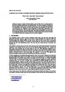
Designers rely heavily upon knowledge that is stored electronically, internally or externally from their companies. During a typical design process the types of knowledge that may be needed includes (but is not limited to) electronic reports, drawings and models of components. Figure 1.1 shows the distribution of a typical design engineer’s time over various tasks on the Internet.
6
86
Send or receive e-mail
84
Locate suppliers or products / materials 75
Obtain product specifications
69
Access product directories 54
Download software
50
Research technology 44
Access newspapers and magazines
39
Research competitors
35
Download CAD drawings
34
Browse for interesting ideas
34
Search databases
24
Subscription service, engineering information
17
Subscription service, business information
13
Check bulletin boards
11
Collaborate on designs
9
Communicate with news groups
9
Transmit engineering change orders 5
Figure 1.1 – How Engineers Use the Internet. (Persun 2000)
These data1 in Figure 1.1 can be interpreted to mean that designers are leveraging current high-speed electronic connectivity. Online design collaboration between suppliers and manufacturers is likely to increase as Internet tools become more supportive and secure. To utilize the Internet for information gathering and modeling in the design process in a secure way, a new generation of supporting tools and methodologies will be required. There are a number of studies undertaken in this area, focusing on how designers find,
1
The numbers represent the percentage of engineers who checked the related box in a reader survey carried out by Design News Journal.
7
access, retrieve and manage knowledge throughout the design process (Dong and Agogino 1996; Marsh 1997; Schott, Buttnet et al. 1997; Keskinocak, Goodwin et al. 2001; Zhang, Chao et al. 2003).
These studies have already generated a relatively secure environment for designers to share their design knowledge over the Internet with suppliers and manufacturers under strict legal contracts. On the surface, this competitive change should result in lower pricing and higher quality products. However in order to protect intellectual property, suppliers are reluctant to share the designs of their products with “window shoppers” without strong and enforceable legal agreements. Putting in place such legal agreements (typically, proprietary information or non-disclosure agreements) requires both money and, more importantly time. It is not uncommon for such agreements to take between six months and a year to put into place. This delay lengthens time-to-market, hampering the search for lower price and higher quality products and slowing down the response to changes in the market.
To date, there is little research seeking to simultaneously leverage collaborative design in an electronically connected environment while protecting proprietary design models. The goal of our research is to enable system integrators to rapidly design their products by use of distributed computational models in the context of an open supply chain and over the Internet, without the need of time-consuming non-disclosure agreements.
8
1.3. Agility Agility, the ability to thrive in an environment of continuous and unanticipated change (Parunak 1996), introduces a new competition for capturing market share in global markets; the competition for shorter product design cycles. The ultimate aim of agile manufacturing is making production respond to market changes quickly and meet the demand on time (Tian, Guofu et al. 2002). High agility gives a firm the flexibility of rapid changes in the production volume, thus decreasing the need for investing capital in excess inventory. Rapidly adjusting the production volume in periods of increased demand will in turn maximize the profit.
Global competition requires manufacturing companies to cope with changing customer demands and in turn, markets that are diverse and highly unpredictable. Capturing customer requirements as quickly as possible is crucial to ensure agility of the company, to adapt and respond quickly and maintain or expand its market share. Typically, traditional centralized manufacturing systems do not enable high agility.
A modern large enterprise almost always depends on its suppliers for raw materials. Broadening the pool of suppliers is advantageous to enterprises in finding the right parts during the design stage of an artifact, or in replacing a component of an existing artifact with a superior one. Therefore, agile manufacturing must make use of all resources that are not only internal but also external to the enterprise. The agility concern enforces major changes on the organizational structure and utilization of the resources of an enterprise in order to broaden its borders.
9
Agility is enhanced by broadening the borders of an enterprise and by bringing it closer to suppliers with closer collaboration, and this in turn brings in the need of utilization of information and communication technologies. Information technology breaks location limitations, enabling any enterprise to seek suppliers globally. This type of coordination will furnish the enterprise with rapid and timely response to market changes and improve the agility of the enterprise.
For example, the design process for Daimler/Chrysler is more than an internal decision issue. An automobile design task in the company starts with decomposing the design conceptually and proceeds with selecting suitable components and developing the procedure to assemble them. This way, different designers, who are not necessarily employees, can work on different features of an automobile (Ames 2000). Max Gates, the manager
of
advanced
technology
and
environmental
communications
at
Daimler/Chrysler says in year 2000, 65 to 75% of components and subassemblies were outsourced by Chrysler (Ames 2000).
The biggest obstacle to achieving a shorter engineering design cycle time is the current techniques applied in engineering design that require knowledge in minute details of manufacturing parts. Due to the competitiveness of the market, suppliers are naturally reluctant to release proprietary design data without legal protections. Our research aims to address these issues by enabling system integrators to rapidly generate and use distributed computational models from suppliers’ internet-published models of parts that
10
protect suppliers’ proprietary information. To achieve this goal, proprietary design data has to be kept in black box models of parts.
1.4. Managing Distributed Information Rapid accessing and retrieval of manufacturing parts and their integration in a simulation environment is crucial in the efforts of reducing cost while increasing quality of the design and the most promising platform for such global accessibility is the Internet. Global accessibility of manufacturing components will also enable the design of products that are closely tied to customer requirements, i.e. custom designs. Definition of success in design has evolved drastically in today’s competitive marketplace, the product must not only be cheap and of high quality, but also it has to conform with the customers’ demands.
Typically, the design of engineering systems incorporates commercially available subsystems. For example, most complex electronic products such as systems for patient diagnosis, workstations and even flight controls of airplanes incorporate integrated electronic circuits that are commercially available from different manufacturers. These parts are generally located in paper based or computer-based design catalogues published by the manufacturers.
11
Design catalogues are typically derived from one or more of the following features of a product: •
Functional characteristics, e.g. tensile strength
•
Structural characteristics, e.g. dimensions
•
Empirical test results, e.g. fatigue characteristics
Design catalogues have been the most efficient and precise way to obtain many specifications for the products for decades. However, they have three disadvantages: 1. Catalogues become outdated quickly. 2. Finding the right part is slow and time consuming. 3. A description of the physical attributes and functional characteristics of a part is not sufficient for its evaluation as an integral part of a total design.
In addition to traditional design catalogues, model-based Internet design catalogues have been suggested (Tumkor 2000). The advantage of model-based catalogues is that they derive the required information directly from the model that is coded in the server, and consequently they are current and reliable. However, these studies typically do not enable model evaluation as an integral part of the distributed assembly. Moreover, current work has skirted the issue of protecting proprietary information.
Distributed Information Management Systems (DIMS) deal with the use of information technology tools to help designers perform tasks related to information processing and management (Haag, Cummings et al. 1998). The objectives of DIMS are:
12
1. Increasing the agility of the company by reducing the speed of the response to changing market demands. DIMS enable this by capturing the market demands every time a product is queried. This also can be utilized to improve customer relationships (Tapscott and Caston 1999). 2. Improving the efficiency of the corporation by allowing frequent information exchange between suppliers and manufacturers. Information exchange is crucial especially in cooperative and concurrent design efforts. 3. Reducing the costs associated with information exchange, negotiations and agreement.
There are two front lines in developing applications in the Internet world. First, there is a continuing effort to bring suppliers and manufacturers together in virtual supply chains. As stated before, applications in this front assume that the collaboration is realized under strict legal contracts; therefore proprietary data is shared openly between collaborators.
The second effort in the Internet world is to bring the manufacturers closer to their customers to increase the commercial agility of the manufacturer company. This front mainly covers the custom design efforts in the industries that produce commercial products for individuals. This is a proven method not only to survey the changing market demands, but also to attract more customers.
13
1.5. Simulation of Distributed Assemblies The majority of large manufacturers have sophisticated web sites that provide information (such as functionality, physical properties, etc.) on their products. This information is generally in the form of design catalogues, which are static unless manually updated. Interactive, model-based Internet design catalogues are not being implemented by most.
Traditional design catalogues do not support input-output type of querying and therefore they are not sufficient in context-dependent use, i.e. evaluation of a catalogue item as an integral part of an assembly. To realize a simulation using distributed models simulatable representations of the models should be made available. A hardware description language such as VHDL (Manual 1993) can be used to build these representations efficiently. However, these representations cannot be transferred to the host of assembly if the intellectual property rights have not been protected with legal agreements.
Transfer of the simulatable representations of models using cryptographic techniques was proposed in the literature (Silva and Katz 1995), (Manual 1993), (Hauck and Knoll 1998). These methods have two important shortcomings; 1. they are platform dependent, and 2. they require considerable effort to update transferred representations when the core model is changed.
14
The simulation methodology that is utilized in this research will address information sharing from a different perspective. In this scheme, proprietary component models will not be transferred to the assembler host, rather they will respond to valid queries by returning a mathematical representation of the functional response surface. As will be shown in Section 4.4.2 and elaborated in Section 6.3, these functional representations cannot be reverse engineered. The MDM methodology (Chapter 6) facilitates dynamic integration of MDM agents in an assembly and the simulation of the assembly as a whole. Consequently, any changes made in an MDM agent can be immediately reflected in the assemblies it participates in. The MDM simulation methodology enables distributed simulation with; 1. platform independency, 2. simple and efficient updating of products, only on the supplier host, and 3. a more open market place, by reducing the concerns in intellectual property protection.
1.6. Internet Applications for Collaboration in Design One of the most remarkable features of the Internet is that it reduces impediments of geographical distance for information exchange. Conceptually, information that is published on the Internet is stored everywhere on the global network. An extension of this is the realization of information exchange between designers and experts who are widely dispersed geographically. The Internet has enabled engineers to collaborate regardless of physical location and this spawned many Internet-based collaboration tools.
15
The advantages of collaboration in design over the Internet (Tian, Guofu et al. 2002) include but are not limited to: 1. Quicker design that is more responsive to the market, 2. Decreased travel time and expenditures, 3. Global availability of experts, 4. Decreased design duplication by reuse, and 5. Increased competitiveness and profit
An interesting application on the Internet is the virtual office structured by Object Services and Consulting, Inc. (http://www.objs.com/survey/vo.htm). The company is in the business of developing software for distributed information management applications. In January 2001, their virtual office employed 8 full time employees and a ¾-time office manager spread across six geographic regions of the U.S. There is no central office and employees report to work by going online at their homes.
ManufacturingQuote (http://www.manufacturingquote.com) is a web site that aims to bring manufacturers and suppliers together on one platform. As of August 2004, it has 30,000 integrators and 1,145 suppliers performing over 200 manufacturing processes. When a manufacturer is searching for a specific component, it posts a Request For Quote (RFQ) on the web site. An RFQ may only include functional requirements or it may specify the structural details with a drawing. Interested suppliers contact the manufacturer directly to propose a quote.
16
The research in collaborative design has already generated a relatively secure environment for suppliers to share their design knowledge over the Internet with manufacturers. Examples of such support include rapid part ordering from electronic catalogues, access to large pools of manufacturers and suppliers, negotiation over the Internet, and a number of other useful capabilities. However the advent of the Internet has not as yet given rise to a simulation environment that leverages its inherent advantages. The changes in the procurement process of enterprises need to be reflected in a new type of design environment that is augmented by simulation-based design testing – one that facilitates parameterization of design by automated searching and locating of satisfying and optimizing parts, integration of selected parts in an assembly, and simulation of the assembly that is distributed over the Internet.
1.7. Goals and Strategies [Future manufacturing enterprises] will need to be information-oriented, knowledge driven, and much of the daily operations should be automated around an Internet environment that connects everyone together. (Tian, Guofu et al. 2002)
Our ultimate goal in this research is to take a step towards Tian’s vision by enabling automated routine design and simulation based design testing of engineering artifacts using computational models that are distributed over the Internet. There are two key problems that impede the realization of this objective in the current wired world. First, in order to protect their proprietary data, manufacturers are reluctant to share their design
17
models with window shoppers without non-disclosure agreements. The second problem stems from the unavailability of automated tools that are capable of both distributed design and simulation-based design testing over the Internet. Most current engineering design and analysis tools are either limited to a local computer; designed to operate on an exclusive virtual design network; or they need a vigorous standardization of distributed resources.
Protecting proprietary design knowledge and openly sharing models that represent device functionality has not been possible with the traditional model based approaches (Chapter 2). We are attacking the problem of sharing design models without revealing proprietary data with the Modular Distributed Modeling (MDM) methodology. As will be demonstrated in Section 4.4 and elaborated in Section 6.3, the crux of the MDM methodology is to share input-output models of engineering artifacts without disclosing their internal dynamics, hence protecting the proprietary information (Byam and Radcliffe 1999; Byam and Radcliffe 2000; Reichenbach 2003; Radcliffe and Sticklen 2005). Eskil et al. described a conceptual infrastructure of MDM community (Eskil, Sticklen et al. 2003) that was implemented by Reichenbach (Reichenbach 2003) for simulation of mechanical structures.
MDM methodology leverages distributed simulation by eliminating the need for uniform model representation, supporting proprietary data protection with black-box modeling, and keeping the network traffic within manageable levels. With these features, MDM offers a valuable platform to assemblers who are seeking off-the-shelf parts for a
18
particular design. However, as the MDM community grows, finding the right parts by browsing through the population of MDM agents will be beyond the reach of a designer. MDM community will benefit from the support of automated tools that are capable of searching, locating and integrating MDM agents and running simulations on the final design.
To address the unavailability of online collaboration tools that support distributed design augmented by simulation-based design testing, we chose to extend the RD methodology with capabilities to parameterize the design with selection of distributed components and to run simulations on distributed assemblies. The underlying reason for choosing this design methodology is the routine nature of most real-world design problems (Section 1.1).
In a series of studies over the past decade, the Laboratory for AI Research of Ohio State University and the Intelligent Systems Laboratory (ISL) of Michigan State University developed several computer based tools for engineering design and analysis. Among these tools, Generic Task Routine Design (GT-RD, Chapter 3) architecture was first suggested and implemented by Brown (Brown and Chandrasekaran 1989) and developed later in the ISL (Sticklen, Kamel et al. 1992; Kamel and Sticklen 1994; MartinezBermudez 2001). GT-RD deals with complex design cases by implicitly breaking the design of an overall system into a hierarchy of sub design problems and capturing an assembly plan to bring the parameterized subassemblies together (Sticklen, Kamel et al. 1992; Kamel and Sticklen 1994; Lenz, McDowell et al. 1996).
19
As discussed in Section 3.4, there are two running modes of a typical RD task. In off-theshelf mode, the output is an assembly plan of a device that is composed of off-the-shelf parts selected from available sets of locally represented components. Ideally, this locally represented design knowledge embodies all potential design components, which is unrealistic due to the vast number of suppliers in today’s market place. Furthermore, legal approval process needed for sharing proprietary information slows down the retrieval of design knowledge drastically. Unless all parts of a model are owned by one corporate entity, proprietary issues prevent timely flow of computational model information.
The thrust of our research is to integrate MDM, and in particular its capability to provide black-box simulation, into the Routine Design methodology. In this scheme, GT-RD provides the framework for routine design of an artifact while MDM provides the framework for assembly of off-the-shelf components and the distributed simulation of the total assembly. The integration of RD and MDM methodologies facilitates an automated distributed routine design scheme augmented with simulation-based design testing, by enabling design parameterization with off-the-shelf components that are distributed over the Internet, virtual assembly of selected components, and simulation of the distributed assembly for design testing (Chapter 5).
The core of our research is the extension of the Routine Design methodology to enable black-box modeling by use of distributed off-the-shelf parts and simulation of the total
20
assembly in the context of open and competitive e-commerce. Our accomplishments in pursuit of our goal are as follows:
Extending the primitives in the GT-RD framework to include design parameterization with off-the-shelf parts that are represented by MDM agents.
Extending the RD methodology by adding the capability of design testing through simulation of distributed assemblies at all abstraction levels of the design.
Extending the MDM methodology to include electromechanical devices.
Demonstrating the applicability of the developed framework by testing it in fuel cell and fuel cell/battery hybrid vehicle design problems.
The deliverable of this research is a conceptual framework and implementation that integrates an information hiding distributed modeling framework into an engineering design methodology. The integrated architecture, RD-MDM, has the following capabilities in both single and multiple routine design cases: 1. Multi-attribute search for suitable design components among a population of remotely represented of-the-shelf design components, 2. Automatically linking and incorporating remote MDM agents as components (subassemblies) of the device that is being designed, 3. Total design testing by running simulations on distributed assembly and its subassemblies at every abstraction level, 4. Publishing the final design as an MDM agent while hiding the proprietary information pertaining to the design.
21
Part II Previous Research
22
CHAPTER 2 Online Collaboration Techniques
One of the most remarkable features of the Internet is that it reduces the importance of geographical distance in information exchange. Conceptually, information that is published on the Internet is stored everywhere on the global network. Ideally in computer-based design, the physical location at which knowledge is stored is not designer’s concern. An extension of this fact is the ability of information exchange between designers and experts over the network. The Internet has enabled engineers collaborate regardless of physical distance and this led to development of many distributed collaboration tools.
The advantages of collaboration in design over the Internet include but not limited to the following (Tian, Guofu et al. 2002): 1. Quicker design that is more responsive to the changes in market 2. Decreased travel time and expenditures 3. Availability of experts around the world 4. Decreased design duplication by reuse 5. Increased competitiveness and profit
The achievability of collaboration between geographically distant organizations gives the enterprises the freedom of researching, designing, developing and manufacturing their 23
artifacts at the most suitable locations. To realize this opportunity the key requirement is an infrastructure of Distributed Information Management Systems (DIMS) that integrates and enables interoperability between distributed information systems. For this reason there is a growing interest among researchers in conceptual frameworks of DIMS.
2.1. DIMS for Internet Based Design The field of expert systems emerged with the start of the DENDRAL project (Buchanan and Feigenbaum 1978; Lindsay, Buchanan et al. 1980) in 19652. The significance of the DENDRAL is the symbolic structures that were coded in the program and held the expert knowledge. The first examples of distributed AI appeared as researchers took the challenge of solving problems that require more diverse fields of expertise. The HEARSAY project (Reddy, Erman et al. 1976) introduced the blackboard architecture for speech understanding and was one of the first to distribute the problem solving process to multiple processors. In the blackboard approach, independent sets of rules (knowledge sources) asynchronously process the acoustics data that is kept in a shared memory (blackboard). Smith (Smith 1981) proposed the Contract-Net mechanism for distributing the tasks dynamically among the nodes of a computing network as well as the data and partial results, which were kept in a shared memory in the blackboard approach. A Contract-Net consists of specialized expert nodes that have internal representations of data. Each node is capable of calling for bids for the tasks that are out of its expertise and bidding on the calls of other nodes. (Buchanan and Mitchell 1978; Davis and Lenat 1982; Buchanan and Shortliffe 1984) 2
The DENDRAL Project continued until 1983 and led to the development of other rule-based reasoning systems such as MYCIN (1972-1980) (Buchanan and Shortliffe 1984), META-DENDRAL (1970-1976) (Buchanan and Mitchell 1978) and TEIRESIAS (1974-1977) (Davis and Lenat 1982)
24
These distributed problem-solving projects produced successful results as long as the knowledge pertaining to the problem domain could be gathered and represented in compliance with the particular architecture. As the problem gets more complex, gathering and organizing the widespread expert knowledge becomes unpractical. An example is the engineering design problems, for which the information is widespread, unorganized, and in general beyond the reach of a single designer (Alexander 1964). MacGregor (MacGregor and Thomson 2001) also emphasized the lack of common terminology between teams of expertise and unawareness of existence of knowledge. In the literature there have been two approaches to solving the common terminology problem, (a) standardizing the representation of knowledge, and (b) encapsulating the knowledge in data wrappers and enabling communication through a predetermined terminology.
Many organizations attempted to standardize the representation of a model, such as STEP of ISO and Integrated Data Model of COMBINE (Augenbroe 1995). STEP is oriented towards exchanging the model data itself, but not the function of the model. To incorporate the designer’s ideas about the model, Fruchter et al (Fruchter, Clayton et al. 1995)
built
Interdisciplinary
Communication
Medium
(ICM),
using
the
propose/interpret/critique/explain paradigm in a cycle of collaborative design. Ball (Ball, Matthews et al. 1998) and Fruchter et al (Fruchter, Clayton et al. 1995; Fruchter, Reiner et al. 1996) developed prototypes that capture design rationale. Rosenman (Rosenman and Gero 1996) proposed a paradigm to describe the semantics of the model, known as purpose-function-behavior structure.
25
Standardization of model representation requires massive conversions from legacy design development platforms and its success heavily depends on its widespread acceptance. This fact encouraged many researchers to develop ways to encapsulate knowledge in modular units called agents and enable communication between agents over a predetermined terminology. We will detail the definition of agent and discuss the concept of agents in the context of distributed problem solving in Chapter 4.
The mechanism that determines the language of communication between agents is termed as Ontology. Chandrasekaran (Chandrasekaran and Josephson 1999) defines ontologies as content theories about the sort of objects, their properties and relations that are possible in a specified domain knowledge. Theoretically the realization of a common universal ontology is possible, but may never exist in practice due to its size, lack of focus, definition of granularity, cultural references and maintenance (Shen, Norrie et al. 2001). The largest ontology developed was in the Cyc project (Lenat and Guha 1990), with 100,000 terms, over a million assertions and trillions of one-step deductions. Ontolingua (Gruber 1992) is a platform developed in the Stanford University for providing libraries of ontologies as well as tools to develop new ones.
PACT is one of the most significant projects that advocate encapsulation of tool data and model representations rather than standardizing them. In PACT, each tool uses the most appropriate internal data structures and representation of models and communicates with a common language. PACT defines three communication languages with varying complexities. Knowledge Query and Management Language (KQML) (Finin, Fritzon et
26
al. 1993) is the lowest level of communication that allows asserting a fact, querying, and responding to other agents. The second level communication protocol is called Knowledge Interchange Format (KIF) (Genesereth and Fikes 1992) and supports predicate calculus for communicating constraints, rules, disjunctions, etc. The highest level protocol is used for the development of engineering ontologies (Gruber 1993). To support the complicated nature of communication between PACT agents, a facilitator mechanism (Cutkosky, Engelmore et al. 1993) is implemented. The facilitator provides an interface between a local connection of agents and remote agents. Its responsibilities include routing and translating messages and monitoring the local problem-solving process. The collection of autonomous agents under facilitators is called a federation architecture.
MetaMorph (Maturana, Shen et al. 1999) is another project that uses the federation architecture to integrate distributed intelligent systems and concurrent engineering tools. In this architecture, the coordination of virtual groups of intelligent agents is realized by the mediator mechanism (Maturana and Norrie 1996). The DIDE project (Shen and Barthes 1996) proposes asynchronous cognitive agents for integrating design and engineering tools and human specialists. In DIDE agents work independently during the design process, but their results are generally monitored by a human agent before they are broadcast to the community.
The DOME project aims to create a modeling infrastructure for individuals to share their simulation services related to their expertise. The ultimate goal is to allow individuals to
27
design and understand complex systems by use of latest modeling technology offered by experts. The infrastructure serves as an interface for the modeling tool once it is published on the DOME server. This research aims more or less towards our goal; allowing individuals to design, simulate and understand complex systems. In the DOME approach this is realized by making design and simulation tools available to individuals on the Internet, whereas our focus is on sharing device models. The DOME approach does not allow sharing of models and assembly of complex systems using distributed components; design of a complex system still requires bringing all components together on a local system.
The approaches mentioned above did not address to simulation of distributed assemblies while protecting the proprietary resources. Gu et al. (Gu, Asada et al. 2002) provide a discussion of the need for protecting proprietary information in engineering design and analysis.
WebCADET (Rodgers, Huxor et al. 1999) envisions routine design over a global network of expert systems. ‘AI as text’ approach lets designers observe and edit rule bases, which embody the experiences of other designers. The original stand-alone CADET was developed to support designers in the early conceptual stages of design. It is built on a knowledge base that provides a structure for defining and structuring the product attributes as text. CADET also provides an evaluation of the proposed conceptual design. CADET moves towards a decentralized structure with WebCADET, where distributed
28
servers serve as experts of specific applications. WebCADET enables engineers to download rule bases from servers and update them for their own purposes.
WELD (Chan, Spiller et al. 1998) enables complete distribution of users, tools and services by treating every component as potentially mobile. For uniform and reliable communication, WELD avoids any coupling between components. Its communication protocols are built on generic string-based messages for extendibility.
WebCADET and WELD are potentially the closest approaches to the focus of our research. Combined, they support complete and scaleable distribution of knowledge over the Internet and intelligent distributed design using uniform communication protocols. However, neither of these studies addressed to simulation over distributed components or protection of proprietary knowledge. Routine Design – Modular Distributed Modeling (RD-MDM) infrastructure introduced in this research embodies all of these functionalities.
The variety of web services offered by companies created a need for integration and interoperability of these services. Keskinocak (Keskinocak, Goodwin et al. 2001) suggested decision support for “business intelligence” by improving the interoperability between web service providers and receivers within a supply chain. One of the most interesting capabilities of this platform is the multi-attribute search. The Universal Description Discovery and Integration (UDDI) Project also aims to automate search and transaction in an e-commerce environment.
29
Today, we can speak of building dynamic and flexible supply chains that are composed of various web services distributed over the Internet (Keskinocak, Goodwin et al. 2001; Zeng 2001). The integration of supply chains over a network has been termed supply webs by Keskinocak et al. (Keskinocak, Goodwin et al. 2001). In a supply web, the products of each supply chain can theoretically be returned to the pool of web services as candidate components for other supply chains, creating dynamic interconnections between potentially geographically distant enterprises.
Although the state-of-the art approaches fold in valuable search and decision tools, they provide very limited capability in automated design and analysis. Spiller (Spiller and Newton 1997) envisions the future of the Engineering Design and Analysis community organized in an integrated and distributed environment. Interoperability between tools and design libraries will create an evolvable, customizable, and adaptable virtual design network. Such an organization would also enable querying products and serve as a virtual consultant to researchers and individuals. RD-MDM aims to create this environment by enabling automated design augmented by simulation-based design testing, using distributed computational models that hide proprietary resources.
2.2. Electronic Product Catalogues Until recently, hard copies of product catalogues have been utilized in selection of parts during the design process. Internet opened a new era in this field by its search engines and online product catalogues. Online catalogues offer inexpensive, fast and up-to-date
30
information on commercially available products and potential for integration of other services such as virtual assembly and simulation.
Electronic product catalogues can be viewed as expert systems whose primary purpose is to help designers search for and locate the right design parts. Internet offers numerous electronic catalogues that are built on top of simple to sophisticated expert systems. Tumkor (Tumkor 2000) proposes on the demand design of shafts and bearings using a web-based approach.
The focus of electronic catalogues can vary from material selection to virtual assembly and
simulation.
MatWeb
(Online
Materials
Information
Resource,
http://www.matweb.com) is an online database of thermoplastic and thermoset polymers, metals, ceramics, semiconductors and other engineering materials. A designer can search through these materials with respect to their properties, compositions or types. Hindman (Hindman and Ousterhout 1998) developed a virtual design system for sheet metal forming over the Internet. Brown and Right (Brown and Wright 1998) developed an integrated DAC/CAPP/CAM environment that is again accessible over the Internet.
Electronic and online product catalogues have proven to be very convenient in the selection of the right part for engineering design. Online catalogues reside on the manufacturer’s server, thus are easy to maintain. When model-based, any change in the functional properties of a part will be reflected on the catalogue immediately to keep the information current. However, most design catalogues do not support virtual assembly
31
and simulation of product items and the ones that do fail to implement protection of proprietary data models.
As will be demonstrated in Section 4.4.2 and elaborated in Section 6.3, the crux of the MDM methodology is to share input-output models of engineering artifacts while protecting pertinent proprietary data (Byam and Radcliffe 1999; Byam and Radcliffe 2000; Reichenbach 2003; Radcliffe and Sticklen 2005). Part of MDM can be viewed as a sophisticated online design catalogue system. Each MDM agent represents an entity (a product) that may or may not be an assembly of other entities. Functional and structural characteristics of the agent are published on the server of the manufacturer, and registered to an agent registry as a member of product type. In this sense, the agent registry can be viewed as a ‘global’ product catalogue and an agent server as a page in this catalogue.
2.3. Systems that Protect Intellectual Property The majority of manufacturers have sophisticated web sites that include downloadable or interactive electronic product catalogues. Current applications on the web are very useful for locating the right part for the design but as stated in Section 2.2 they are either weak in evaluating the part as an integrated component of the design or do not support it all together. In the literature, simulatable views of the product catalogues at multiple abstraction levels have been proposed.
Researchers (Silva and Katz 1995; Hauck and Knoll 1998) proposed cryptographic techniques for transferring simulation models of components without revealing
32
proprietary information. These cryptographic techniques are simulator dependent and require manufacturers to maintain a different database of appropriate simulation models for each technique. Moreover, they require considerable effort to update transferred representations when the core model is changed.
HelaiHI (HelaiHl and Olukotun 1997), Dalpasso (Dalpasso, Bogliolo et al. 1999; Dalpasso, Bogliolo et al. 1999) and Fin (Fin and Fummi 2000) proposed simulation to take place on the manufacturer site by use of ad-hoc languages to model the functionality of the component. These approaches offer a solution for the protection of proprietary information at a cost of extra work and possible discrepancies between the design and component models. Also, with this approach it is difficult to assemble a design that incorporates components from different vendors.
We propose the simulation to take place on the designer’s computer, while eliminating the need to download component models. Remote MDM models over the Internet serve as integrated components of the overall design by responding to queries with single-shot answers or returning a mathematical representation of the response surface that can not be reverse-engineered (Sections 4.4.2 and 6.3). In either case, design details and therefore proprietary information is not revealed and design and simulation can proceed as if the actual models were present on the local computer.
33
CHAPTER 3 Generic Task – Routine Design
Engineering design has been defined in many domains. Each definition has been more or less specific to the domain of definition. Dym and Levitt attempted to define engineering design outside of any particular domain context, i.e. independent of a domain. (Dym and Levitt 1991; Dym 1994): Engineering design is the systematic, intelligent generation and evaluation of specifications for artifacts whose form and function achieve stated objectives and satisfy specified constraints.
Design problems often lack a well-defined objective that is expressed in the form of mathematical formulae. Moreover, in the conceptual design stage design parameters may be ambiguous or unknown, which renders the design problem under-specified or ill structured.
A design problem statement can be as “simple” as “Design a concept car”. Many design tasks exhibit such open-endedness in the conceptual design stage. When faced with such an assignment, the first task of a design engineer is to define the problem. “What is trendy presently?”, “What is the budget of this project?”, “What type of an automobile?” and many other questions have to be answered before more concrete design process commences.
34
This example demonstrates the two most difficult characteristics of design processes; they are open-ended and ill-structured. Designing a concept car is an open-ended design activity since the ultimate goal is not crisply defined. It is also an ill-structured problem due to the decisions that must be made about the type of the automobile, its power, the driving conditions, etc. Most, if not all, design problems exhibit such open-endedness. Typically a design process has more than one solution, each with different benefits and limitations. The first challenge of a designer is to eliminate the design alternatives that are infeasible by applying constraints on the solution.
In most cases, the actual engineering design process starts with estimation and assumption. A first rough estimate is often a quick sketch, which is also referred to as back-of-the-envelope or rough design. Rough design enables the designer to make a quick evaluation of the design in the conceptual stage. The idea will be carefully elaborated and a fully detailed design will be established if the design appears feasible, and will be rejected otherwise.
One of the most effective practices in engineering design is the reuse of existing designs. This was stated by Glegg (Glegg 1969) decades ago: Now one of the [best] ways of designing something is not to design it at all. Use [a part] that is designed already by someone else.
Rough design and design reuse are exploited in Routine Design (RD) (Brown 1984; Sticklen, Kamel et al. 1992; Dym 1994). In this scheme, the design of a complex system
35
starts with breaking the functionality of the overall system into simpler and sometimes existing subsystems and developing an assembly plan to bring these subsystems together. After the design knowledge is incorporated in the subsystems, it is up to the strategies of routine design process to carry out necessary modifications and most importantly the assembly process methods to bring together the individual systems into a complete design.
3.1. The Routine Design Process Quite often when an engineer designs similar artifacts over and over again, he achieves a grasp of routine nature of the process and starts discovering effective ways to decompose the design process into a hierarchy of design steps such that the coupling between these steps are minimized. Although he may not know beforehand all possible situations that could occur in a design process, he acquires an understanding of design choices and plans that specify the order of making the choices. Routine Design (RD) is a procedure that aims to capture this expert knowledge and realize it in computer environment.
Experience has shown that design of a complex system can be effectively fulfilled by breaking the functionality of the overall system into simpler and sometimes existing subcomponents and developing an assembly plan to bring these subcomponents together. Particularly in the design of domestic consumer products such as household goods, furniture and automobiles, the focus is not to produce a product from scratch, but rather to modify certain aspects of an available design in an attempt to improve performance (Hubka and Eder 1996). Typically in such design tasks the design knowledge is available,
36
but an understanding of how exactly the design knowledge should be applied is lacking (Rodgers, Huxor et al. 1999).
For instance, the first step in routine design of an automobile would be the hierarchical decomposition of the task of overall design until manageable complexities are achieved in each sub-task. After the design knowledge is incorporated in the sub-tasks, it is up to the strategies of routine design process to carry out necessary modifications and to the assembly process methods to bring together the individual components into a complete automobile.
Routine design should not be considered as a design tool that is applicable only to simple design problems. A complete routine design structure could represent any complex design that has been realized before and could offer numerous solutions to the design problem. Routine design is not applicable only to novel design problems in which the required knowledge about the design strategies, or depending on the application, potential design components or the physical and functional attributes of component types is unavailable, or obtained during the design process.
3.2. The GT Approach to the Engineering Design Process Generic Task (GT) approach proposes that complicated knowledge systems can be built using primitive problem solving types that are called “generic tasks”. Each generic task captures the knowledge and control strategies that are characteristic to its domain. The
37
GT approach to problem solving was first proposed in the Ohio State University in early ’80s (Chandrasekaran 1983; Chandrasekaran 1988; Chandrasekaran and Johnson 1993).
The strategy of GT approach is to identify the “building blocks” of reasoning strategies such that each building block is both generic and widely useful as components of complex reasoning systems (Chandrasekaran 1988). Each GT is a strategy from the viewpoint of the problem, which it is helping to solve. It is a task from the viewpoint of the functionality that is to be achieved by the GT. It is in this sense both a strategy for a task and a task in itself.
A Generic Task is characterized by (Chandrasekaran 1988): 1. The type of knowledge it embodies and the representation of its knowledge. This defines the functionality of the generic task. 2. A representation and organization of the domain knowledge including a vocabulary of knowledge types. 3. The problem solving process (control strategy) that the task uses. This is a vocabulary of inference and control of the task.
Each generic task is a task-specific and reusable executable shell that supports knowledge acquisition and system implementation in cooperation with other generic tasks. A number of generic tasks have been identified in the literature (Chandrasekaran 1983; Chandrasekaran 1988; Chandrasekaran and Johnson 1993) and implemented in the AI
38
Research of Ohio State University and the Intelligent Systems Laboratory (ISL) of Michigan State University. •
Hierarchical Classification aims to classify the description of a particular situation in a given classification hierarchy of related situations (Chandrasekaran and Mittal 1979).
•
Hypothesis Matching aims to determine if a hypothesis matches a set of data that represent a problem state or situation (Bylander and Goel 1988).
•
Functional Reasoning aims to describe a complicated design by recursively decomposing its functions into a number of components until ‘functionally understood’ components are reached. Functionally understood in this context means that the operations to achieve the functionality of the component are known. Functional reasoning has been used to answer “what would happen if” type of questions, given an understanding of how a device works (Sticklen and Chandrasekaran 1985).
•
Abductive Assembly of Explanatory Hypotheses proposes an explanation to a portion of a data by constructing a composite explanatory hypothesis out of the given hypotheses (Josephson and Josephson 1994).
•
Routine Design involves with generating a design description by sequentially choosing the design parameters in order to meet design requirements (Brown 1987; Sticklen, Kamel et al. 1992). Multiple Routine Design, a generalization of routine design developed in the ISL, aims to generate multiple feasible design descriptions (Sticklen, Kamel et al. 1992; Kamel and Sticklen 1994; MartinezBermudez 2001).
39
Our research introduces new links into RD at the level of functionality. We aim to realize new extensions to GT Routine Design by incorporating a distributed agent-based methodology in the GT shell. The current version of GT Toolset works on stand-alone computers whereas our enhancement on the system will enable distant communication via the Internet for distributed problem solving. Also with this research, we are extending the Routine Design methodology with automated design testing by running simulations over distributed assemblies.
3.3. Routine Design Using the GT Approach The introduction of the GT approach (Chandrasekaran 1988) lead Brown and Chandrasekaran (Brown and Chandrasekaran 1989) to define Routine Design methodology and its representation language, Design Specialists and Plans Language (DSPL). The GT-RD architecture is capable of solving complex design problems (Sticklen, Kamel et al. 1992; Kamel and Sticklen 1994; Lenz, McDowell et al. 1996) when an abstract design plan is obtained from a domain expert and captured in the GTRD representational language.
Design requirements are generally qualitative in nature. For this reason, it is sometimes preferable to obtain multiple feasible design specifications to consider and choose the preferred solution. DSPL considers design plans one by one until it reaches an acceptable solution and quits afterwards. To expand the utility of DSPL, Kamel (Kamel and Sticklen 1994) developed Multiple Design Specialists and Plans Language (MDSPL) inference strategy. MDSPL instantiates all design plans and returns a list of all plausible design
40
solutions after eliminating the ones that do not meet design requirements. This list will most certainly include the design that would be proposed by DSPL.
3.4. Procedure of GT-RD GT-RD decomposes the design problem into a hierarchy of cooperating specialists (Kamel and Sticklen 1994), each responsible for a specific aspect of the overall design. Typically, lower-level specialists in this hierarchy represent actual components of the design and are responsible for parameterizing the design with a suitable component (offthe-shelf mode) or parameterizing a generic component. As RD proceeds higher in the specialist hierarchy, conceptual aspects of the design problem become more and more pronounced.
The off-the-shelf running mode of GT-RD was demonstrated in COMADE (Sticklen, Kamel et al. 1992) on a routine design example of composite materials. In this example the manufacturing of a composite material was parameterized by locally represented components (amines, fibers) and processes (curing conditions). In one dimension, our research extends this example to remotely represented components and processes. Each specialist in the decomposition structure is furnished with a set of design plans. These plans are specified by the designer during the structuring of the task-specific routine design system. To choose an appropriate design plan, a specialist invokes the plan selector, which in turn refers to the sponsors of each plan, as depicted in Figure 3.1. A plan sponsor matches the status of the design with the conditions for applicability of the
41
plan and reports the level of suitability of the plan it represents. A plan is initiated only when it is evaluated as suitable by its plan sponsor and chosen by the plan selector.
Figure 3.1 – The Architecture of GT Routine Design
Design plans consist of ordered instructions to select actual components (off-the-shelf mode) or to assign values to attributes of generic components that are addressed by the design goal of the specialist. To fulfill its task, an initiated design plan may invoke other specialists, execute design tasks and check constraints. In case the design of a subsystem fails, design critique at that abstraction level tries to determine the reason for the failure and invokes the redesigner to take corrective actions, which may result in selection of a new plan.
When a specialist successfully completes the part of the design it is responsible from, it hands in the design parameters to its parent specialist, where all sub-designs from one lower level are merged into a higher-level design and checked for constraints. The design
42
of the artifact becomes more complete as the design process progresses up in the design abstraction hierarchy.
3.5. Types of Knowledge and Control Strategies in RD RD embodies four types of knowledge (Martinez-Bermudez 2001): 1. A decomposition of a class of design problems into a hierarchy of smaller design problems. This hierarchy is built so that the coupling between sub-problems is minimized. 2. Design plans that hold procedural knowledge. 3. An evaluation scheme for selecting appropriate design plans. 4. Knowledge for adjusting the design when the design fails (i.e. at least one constraint is not satisfied).
Both in Routine and Multiple Routine Design (MRD), design starts with the upper-most specialist (top specialist) and flows through the lower level specialists until all successors of a specialist complete their design tasks. Then the design process proceeds backwards, by merging the pieces of design from lowest to highest level in the hierarchy of specialists. In this process, each specialist carries out the following actions: 1. Plan selection 2. Design refinement 3. Redesign, in case the plan fails
43
During RD, only one plan is selected at a time, and plan selection stage is terminated as soon as a plan of the top specialist is successful. In MRD however, all applicable plans at all abstraction levels are initiated and a list of feasible design options are returned. Kamel et al. (Kamel and Sticklen 1994) suggest that instead of programmatically choosing a feasible design, displaying the design alternatives to the designer and leaving the final decision as a post-design activity is more practical in the real world applications. With this approach, the designer has the benefit of having multiple design options at his disposal and the ability to view their performances and compare them. Kamel et al. propose displaying the design alternatives and their performance measures in the form of a merit table.
44
CHAPTER 4 Modular Distributed Modeling
The Modular Distributed Modeling (MDM) methodology plays and imperative role in our research with its support for input-output model sharing of engineering artifacts in the context of open, competitive e-commerce. MDM achieves this remarkable functionality through its particular architecture that capitalizes on the Functional Response Modeling (FRM) Technique (Byam and Radcliffe 1999; Byam and Radcliffe 2000; Reichenbach 2003; Radcliffe and Sticklen 2005).
MDM has been developed in a joint research between the Intelligent Systems Laboratory (ISL) and Dynamic Systems Laboratory of MSU. Over the last five years the results of this joint research has laid the groundwork for capability to perform black box simulation and modeling of distributed engineering models (Byam and Radcliffe 1999; Byam and Radcliffe 2000; Eskil, Sticklen et al. 2003; Reichenbach 2003). Furthermore, the MDM research has set the backing for our research that focuses on automated engineering design.
This chapter will start with an introduction to agent technology and multi-agent systems. Next, we will discuss different approaches to integration of distributed models for cooperative design. We will conclude this chapter with a discussion of the MDM
45
methodology in the context of distributed simulation and a detailed description of the FRM approach.
The theory that is elaborated in this chapter will serve as a basis for our discussions in Part III, where we develop the MDM architecture to support a population of MDM agents and integrate the MDM methodology in the Generic Task – Routine Design tool.
4.1. Object Oriented Engineering Object-oriented technology is a way of organizing systems around real-world concepts such that each object represents an important concept (Tian, Guofu et al. 2002). An object encloses structural and behavioral aspects pertaining to the object it represents (Taylor 1995). Any number of objects can be brought together as instances in a class, whose purpose is to hold a generic definition of similar objects. A class can also be the superclass of another, carrying its knowledge over to its children.
Objects can perform operations and carry out actions such as responding to a query for its attributes or querying other objects. Querying other objects is often performed as request for providing a service. The queried object will respond as long as the service is defined in its behavioral attributes. An object would refuse to reveal any details about itself, including its structural and behavioral attributes, unless that service is coded in its behavioral attributes.
46
Object-oriented engineering is shown to provide higher productivity and flexibility for the information systems over conventional engineering (Rumbaugh, Blaha et al. 1997; Dunne and Gray 1999). In our research we will also exploit the knowledge-hiding capabilities of object-oriented engineering, specifically in design engineering using the distributed systems approach.
A distributed system is a collection of autonomous computer processing and storage elements interconnected through a network to achieve integrated functions (Khanna 1994; Simon 1996). In the literature, the merging of distributed systems and objectoriented technology is commonly referred to as distributed object technology (Verwijmeren 2000). This merging is often done using commercially available interobject communication technologies such as Common Object Request Broker Architecture (CORBA) and Distributed Component Object Model (DCOM).
4.2. The Agent Technology An agent can be described as an entity with attributes considered useful in an engineering domain (Tian, Guofu et al. 2002). Agent technology has been used in the distributed manufacturing systems extensively (Shen 1999), however its application in the engineering design has been very limited.
Autonomous agents can accomplish tasks without supervision, thus they are inherently intelligent. Intelligent agents can be fixed or they can be mobile, where objects can move from one platform to another to fulfill their goals. Information agents are mainly utilized
47
on the Internet to filter and organize unstructured data. In general, agents are characterized by one or more of the following attributes (Bradshaw 1997; Doran, Franklin et al. 1997; Dautenhahn and Numaoka 1998; Tian, Guofu et al. 2002): •
Adaptivity: Ability to learn and improve with experience
•
Autonomy: Self controlled and goal directed behavior
•
Collaboration: Ability to cooperate with other agents to fulfill a common goal
•
Inferential capability: Ability to perform abstract tasks
•
Knowledge-level communication capability: Ability to communicate with other agents with terms understandable by humans rather than symbolic representations
•
Mobility: Ability to migrate from one platform to another to accomplish a goal
•
Personality: Ability to emulate human characteristics
•
Reactivity: Ability to sense and act autonomously
•
Temporal continuity: Persistence of identity and state over extended periods of time
MDM agents exhibit several of these characteristics. They have knowledge-level communication capability; they communicate with string-based messages a designer would convey to her colleagues, such as “What is the cost?” or “How many days would it take to deliver?”. They are reactive to incoming queries and requests; if an MDM agent is an assembly of other agents, it may choose to respond to a query by querying its subcomponents and bringing their responses together. MDM agents are also persistent in identity and state over their lifetime, which is defined by the designer.
48
Integration of MDM in RD furnishes MDM agents with additional capabilities. RDMDM realizes MDM agents that are capable of inferential reasoning in the sense that they are furnished with design tools to produce feasible designs on abstract descriptions. They are also cooperative and autonomous with the ability to search, locate and incorporate other design agents in performing their design tasks. An additional autonomous and inferential task performed by RD-MDM is proposing new design alternatives to the designer and taking corrective action by replacing its MDM agent’s subcomponents that are no longer available on the network.
4.3. Multi-Agent Systems In distributed systems approach, a Multi-Agent System is defined as a network of objects with problem solving capabilities, working together to accomplish tasks that are beyond the capability or knowledge of a single object (Tian, Guofu et al. 2002). Recently, the term Multi-Agent System is being used for all systems that are composed of multiple autonomous components and have the following characteristics: •
A single agent is incapable of solving the problem
•
There is no global control on the population of agents
•
The knowledge is decentralized
•
Computation (and sometimes, communication) between agents is asynchronous
RD-MDM is a multi-agent system. In RD-MDM framework, an assembly MDM agent has to incorporate other MDM agents to solve the posed design problem. There is also no global control on the population of MDM agents; every action is initiated by an MDM
49
agent and responded by the addressed MDM agent. An MDM agent encloses the knowledge associated with its design characteristics only; therefore the design data is distributed over the agents that exist in the hidden hierarchical decomposition of the agent. Finally, both computation and communication are asynchronous among the MDM agents.
4.4. The MDM Methodology There are numerous design tools that aim to bring teams of designers together. Many of these tools are meant to be used in closed teams of designers and therefore do not facilitate access to external knowledge. Many organizations attempted to standardize the representation of a model, such as STEP of ISO and IDM (Integrated Data Model) of COMBINE (Augenbroe 1995). Mcalinden et al (Mcalinden, Florida-James et al. 1998) also studied a new STEP based DIMS. Dias (Dias 1996), Bjork (Bjork 1992), (Bjork 1992) and Bjork and Penttila (Bjork and Penttila 1991) also have various studies in this field.
STEP is oriented towards exchanging the model data itself, but not the function of the model. To incorporate the designer’s ideas about the model, Fruchter et al (Fruchter, Clayton et al. 1995) built Interdisciplinary Communication Medium (ICM), using the propose/interpret/critique/explain paradigm in a cycle of collaborative design. Ball (Ball, Matthews et al. 1998) and Fruchter et al (Fruchter, Clayton et al. 1995; Fruchter, Reiner et al. 1996) developed prototypes that capture design rationale. Rosenman (Rosenman
50
and Gero 1996) proposed a paradigm to describe the semantics of the model, known as purpose-function-behavior structure.
Standardization of model representation, even if successfully developed, requires massive conversions from old design development platforms to the standardized. Realizing this transformation and gaining admittance from all sectors of the industry is certainly a big challenge that is faced by these approaches. With the standardization approaches, years of design work will have to be translated to the new representation and this is exceedingly costly for many enterprises.
This was foreseen by Gauchel et al. (Gauchel, Vanwyk et al. 1992), who modeled the distributed knowledge sources as autonomous components that interact by message passing. Feijo et al. (Feijo, Gomes et al. 1998) implemented CORBA to develop such a distributed modeling environment. Both of these studies are big steps towards our vision. These studies however do not support a design platform augmented by simulation and cease to implement proprietary information hiding.
We are asserting that how a specific product is designed and its design details do not have any relevance to how the product integrates structurally and functionally in a larger design. Therefore distributed models can reside on various platforms and communicate on a predetermined ontology that specifies the query and response formats while hiding the proprietary knowledge. A large pool of freely available distributed models will have
51
exciting effects on the process of engineering design such as automated routine design and simulation based design testing on a global network.
Bandwidth is a major concern in distributed simulations, especially when the simulation is iterative in nature. For instance, the programming complexity of the simulation of an assembly that is composed of n components, which communicate with n-1 other components only once in a simulation step, would be in the order of n2. This complexity is even more pronounced when the time slices get smaller for higher accuracy in the simulation. The Functional Response Modeling (FRM) technique that is elaborated in the next section supports simulation over intellectually protected distributed components while keeping the network traffic within manageable levels.
4.4.1. Functional Response Modeling When an MDM agent is queried, it may return a one-shot response or a Functional Response Model (FRM) of the queried attribute. Functional Response Models are critical in development of a methodology and computational mechanism that allows us to achieve functional response of the device held by the MDM agent. Some discussion here is necessary before we move on to discuss background work in this area and an example that shows our current capability.
We start with an observation: traditional methods of device simulation will not be effective over the Internet. Even very sophisticated simulation methods relying on objectoriented design currently still entail a large amount of communication between various
52
components of a simulation object. In a tightly connected, very high speed environment, this may be effective. In the current Internet environment, or even in the “Internet 2” environment, it will not be effective because of the enormous load on network traffic that would be entailed. Consider for example state space simulation where multiple communications between derivative functions are required for each time step of the simulation. The situation for state space simulation is not unusual in terms of required communication load. Thus a major hurdle we had to overcome was to conceptualize and implement as proof of principle a new way to carry out simulation of engineered devices that would minimize Internet traffic.
We have surmounted that hurdle by conceptualizing a type of simulation output that for MDM agents is in response to questions asking for a functional response answer. Instead of many thousands of iterations between a requesting MDM agent, and the responding MDM agent, our output form enables one response to be made by the responder. The requesting MDM agent is then able to use the single functional response answer as the basis for local (to it) simulation that incorporates the device of the responding MDM agent into its own (the requesting MDM agent) device assembly. This is the core result that will enable MDM communities in an Internet environment.
In the next section we will discuss one specific type of functional response: functional response answers to queries of mechanical structures in the domain of structural analysis (Byam and Radcliffe 1999; Byam and Radcliffe 2000; Eskil, Sticklen et al. 2003; Reichenbach 2003; Radcliffe and Sticklen 2005). Although the example below is
53
distinctly in the realm of mechanical engineering, it is centrally important to remember that our entire approach depends on the ability to both hide proprietary simulation models, while at the same time incorporating the device represented by its MDM agent into a higher-level simulation model. The example sketched below is a proof of principle result that developing functional response methodology is feasible explicitly in the structural analysis domain.
Port 1
Port 2
u 1 y1
u 2 y2
… Port p
u p yp
Component
Figure 4.1 – Modular Modeling Element Graphical Notation Power flows into port i if ui and yi are both positive.
Figure 4.1 shows a diagram of a contracted model for an Internet design agent model. The component’s algebraic model is in the standard stiffness form. Modular modeling element graphical notation represents user-defined multi-port multi-DOF subsystem models with a rectangle.
The bold lines represent the power ports with implicit
standardized direction of positive power into the element and standardized input-output port causality. Standardization of positive power direction and input-output causality standardizes the modular modeling elements’ internal formulation, which is the essence of modular modeling.
54
In this example, the detailed physical response model of a component is in the standard stiffness form: Ky = u
(4.1)
where K is the component stiffness matrix, y is the component generalized displacement vector and u is the component input vector. In general, the component stiffness matrix is singular and cannot be inverted. This situation occurs because component models have zero eigenvalues from “rigid-body modes” representing components with no applied boundary conditions. An example for this situation is an unconnected structural element, such as a beam that is free to translate in any direction.
Modular modeling connector constraints implement standard output and power constraints.
The connector constraint forces two connected modular element ports’
outputs, i and j, to be equal and their power flow to sum to zero to conserve power. The power flow constraint is translated to equal and opposite inputs at connected modular element ports since the product of power port variables is power. The defining relationships for all connector constraints (Eq. 4.2) stay the same.
~ Wi = W j
(4.2a)
where:
Wi = f i xi ~ W j = y ju j
55
(4.2b)
The modular modeling connector constraint graphical notation represents connectors with a bold port line between modular elements (Figure 4.2). By definition, connectors have the compatible input-output structure to modular elements. The bold lines have implicit standardized direction of positive power into the connected modular element ports, i and j and modular connector constraints.
The modular connector has the flexibility to
assemble by pairs any number of modular element power ports because modular modeling elements have an internal junction structure at each port (Byam and Radcliffe 1999). The only function of modular modeling connectors is to constrain connected modular element ports.
Byam, Radcliffe and Sticklen (Byam and Radcliffe 1999; Byam and Radcliffe 2000; Radcliffe and Sticklen 2005) have developed a methodology for generation of structural response and the technique of model contraction for modular assemblies. In the following section we will cover this new technique.
4.4.2. Deriving FRMs for Assemblies
The Subsystem Model (Figure 4.2) is a demonstration of the possible situations that can arise when components are assembled into subsystems. The subsystem model has two components connected via constraints on port variables on ports 3 and 4. The subsystem has internal component ports 2 and 5 that are not connected externally. Finally, the assembly has port 1 and 6 that can be connected externally. Once assembled, a new algebraic equation set in the form (Eq. 4.1) is required so that this system can be used in higher-level system models. Because the component models are often singular, the
56
subsystem model will also be singular in general. Only when assembled with sufficient boundary constraints do models become non-singular and solvable.
u 1 y1
u 3 y3
f1 x1
u 5 y5
u 2 y2
u4 y4
f2 x2
f5 x5 f4
f3 Component 1
f6 x6
join
x3
x4
Component 2
Assembly
Figure 4.2 – Subsystem Model with Two Components Each component is depicted with external, internal and connected ports. (Radcliffe and Sticklen 2005)
For deriving the FRM for the assembly, the equations for each of the components are first assembled into the unconstrained system matrix, which is the unassembled dynamic inverse simulation model for the assembly (Radcliffe and Sticklen 2005). K 1 0
0 y 1 u1 = K 2 y 2 u 2
(4.3)
The expanded subsystem equations k11 k 21 k 31
k12 k 22 k32
[0]
k13 k 23 k 33
[0] k 44 k 54 k 64
k 45 k 55 k 65
57
y1 u1 y 2 u 2 y3 u3 = k 46 y 4 u 4 k 56 y5 u5 k 66 y6 u 6
(4.4)
have the connection constraints applied to generate a set of subsystem equation written in terms of the subsystem’s external port variables only.
The subsystems components are uncoupled in this form. The modular matrix assembly equations transform the component input-output pairs (f i , x i ) to the single assembly input-output pair (u, y ) . The join output constraint defines each component’s output x ) in terms of the assembly output vector ( y ). vectors ( ~
~ x = Sy
(4.5)
The power constraint on the assembly requires the sum of the work into all joined ~ component ports Wi = xi f i to equal the applied work W j = y j u j at any assembly connection. The causality in energy domains is defined such that this holds for every physical system in these domains (Radcliffe and Sticklen 2005)
.
~ ~ xT f = yT u
(4.6)
Substituting (4.5) into (4.6) and factoring y T from both sides results in the modular join
~ input constraint between assembly’s component input vectors f and assembly input vector u . ~ ST f = u
(4.7)
Model assembly starts with the unconstrained grouping of all component models into an unconstrained assembly model as shown in Equation 4.3,
58
[K 1 ] ~ ~ [0] Kx = [0] [0]
[0] [0] [K 2 ] [0] [0] [0] [0]
[0] x1 f1 [0] x 2 f 2 = [0] [K n ] x n f n
(4.8)
To obtain a concise modular model, we will now apply the constraints through matrix operations. The assembly output constraint is applied by substituting constraint (4.5) into (4.8): ~ ~ KSy = f
(4.9)
Multiplying both sides with S T and using (4.7) yields the constrained assembly internal stiffness model
ˆy =u K
[
(4.10)
]
~ ˆ = ST K where K S (Radcliffe and Sticklen 2005).
This simple system is the assembled dynamic inverse simulation model. It has constants from the original system contributing to an algebraic combination of addition, subtraction, multiplication and division. The particular form of this function is dependent on the topology of the subsystem and is non-linear in the parameters. The original engineering data from which this model is developed is well protected from reverse engineering – one principle objective of this modeling system. The protection of
59
intellectual property through MDM methodology will be discussed at a more abstract level in Section 6.3.
4.4.3. MDM for Simulation of Distributed Assemblies The research in distributed design has made steady and significant progress in collaboration between design teams within an enterprise or collaboration between the enterprise and its captive suppliers, under strict proprietary agreements. As we discussed in Chapter 2, none of the earlier projects focused on the issue of providing a modeling and simulation environment by making use of the intellectual property that is distributed over the Internet. Although some research addressed to information hiding, these approaches are either simulator dependent or inapplicable when components from different suppliers are present in the assembly model.
The MDM methodology meets the challenge of distributed, collaborative modeling and simulation in the context of open e-commerce by defining MDM agents that exploit the Functional Response Modeling technique. In this framework, an agent represents a physical device that can be linked as a subagent (a component) of an encompassing agent. Each atomic (sans subagents) agent has a local resource that holds its FRM, i.e. the proprietary information hiding simulation model of the device it represents. Moreover, each assembly agent is furnished with the capability to derive its FRM by joining the FRMs of its subagents.
60
The MDM methodology achieves its strength in simulation of distributed assemblies by enabling transfer and joining of proprietary information hiding device models. Modeling with MDM agents however is a manual process, which consists of searching and locating suitable subagents and linking them to the design. Design testing by running simulations on the joined FRM also requires the supervision of a human designer.
As the MDM community grows, browsing through the population of MDM agents to locate the subagents will be beyond the reach of a designer. One of the goals of this research is to leverage the distributed modeling and simulation capabilities of the MDM methodology with the support of an automated engineering design tool. In Part III, we will first reflect on our rationale and proceed with building of a conceptual framework that supports automated, distributed routine design with MDM agents.
61
Part III RD-MDM
62
CHAPTER 5 Problem Statement and Research Milestones
In Part II we described prior research, pointing out their potentials and limitations in the context of cooperative engineering design. In Chapter 2 we noted that most current engineering design and analysis tools are either limited to a local computer, need a vigorous standardization of distributed resources, or designed to operate on an exclusive virtual design network. Furthermore, we stated that protecting proprietary design models and openly sharing the functional capabilities of distributed models has not been possible with traditional model-based approaches. In Chapters 3 and 4 we detailed two key methodologies for our research; Routine Design and Modular Distributed Modeling.
Two observations were made in Chapter 3 with regard to Routine Design (RD) methodology and the current architecture that supports RD, Generic Task – Routine Design (GT-RD) platform. First, the RD methodology performs design testing by checking pre-specified constraints. In other words, simulation of the total design has not been incorporated in the RD methodology. The second observation is that the current RD platform is limited to stand-alone computers.
In Chapter 4 we demonstrated the Modular Distributed Modeling (MDM) methodology, which supports input-output model sharing of engineering artifacts in the context of open, competitive e-commerce. The MDM methodology capitalizes on the Functional
63
Response Modeling (FRM) technique to support protection of proprietary information and simulation of distributed assemblies while minimizing the network traffic.
These discussions have established the foundation for the problem statement and the line of reasoning for our approach. In this chapter we will explicitly state the problem we are undertaking and present the phases of our research. The underlying assertion in developing our solution approach is that realizing the real potential of RD and MDM is a natural outcome of their synergism.
5.1. Problem Statement Since the introduction of CAD into design, there have been vast improvements in individual and collaborative design with the help of computer tools. Today the biggest challenges in distributed agent based design are: 1. Difficulty of defining a complete product model due to the model complexity or size. 2. Insufficiency of design tools that address design across different engineering domains. 3. Unavailability of compatible models across different engineering domains, even between different manufacturers within the same engineering domain. 4. Unavailability of tools that support distributed simulation for design testing. 5. Unavailability of knowledge on design products for proprietary reasons. 6. Keeping network traffic within manageable levels during online collaboration efforts.
64
The first challenge of defining an inclusive model for complex designs is generally dealt with breaking the functionality of the overall system into simpler and sometimes existing subsystems and devising an assembly plan to bring these subsystems together. Generic Task – Routine Design (GT-RD) platform implicitly achieves this functionality provided that design strategies, models of potential design components or physical attributes of components to be parameterized, and assembly plans are known beforehand.
The GT approach (Section 3.2) addresses to the second problem of design across different domains by proposing Generic Tasks, each of which captures the knowledge and control strategies that are characteristic to its domain. The strategy for defining Generic Tasks is to identify the building blocks of reasoning strategies such that each building block is both generic and widely useful as components of complex reasoning systems (Chandrasekaran 1988). GT-RD is a Generic Task that was identified by Brown (Brown 1987), and is applicable to a certain type of problems (Section 3.1) regardless of the engineering domain.
The third challenge, the unavailability of compatible models, has been addressed by many researchers (Bjork and Penttila 1991; Bjork 1992; Bjork 1992; Augenbroe 1995; Dias 1996; Mcalinden, Florida-James et al. 1998). The MDM approach asserts that the internal architecture of a model does not have any relevance to how the product integrates structurally and functionally in a larger design (Eskil, Sticklen et al. 2003). MDM agents communicate only through message passing, and integrate in complex designs through FRMs, which are nothing but representations of n-dimensional response surfaces (Section
65
4.4.1). Since the actual models are not transferred between platforms, the problem of uniform model representation is alleviated.
The MDM approach also addresses distributed simulation, protection of proprietary data, and keeping the network traffic within manageable levels by use of the FRM technique. Distributed simulation with MDM agents was discussed in Section 4.4.3. As demonstrated in Section 4.4.2 and will be elaborated in Section 6.3, the FRM technique loses the internal topology of the assembled device, thus hiding the proprietary data. Transfer of FRMs during simulation reduces the number of communications to one for each subcomponent, significantly reducing the network traffic.
5.2. Synergy of RD and MDM Methodologies As discussed above, the RD methodology meets challenges 1 and 2 in collaborative design. However, current implementations of RD require gathering of broad design knowledge that ideally represents models of all potential design components on a single computer, which is unrealistic due to the vast number of suppliers in today’s market place. Furthermore, legal approval process needed for sharing proprietary information slows down the retrieval of design knowledge drastically. Unless all parts of a model are owned by one corporate entity, proprietary issues prevent timely flow of computational model information.
66
On the other hand, the MDM methodology leverages distributed modeling and simulation by meeting challenges 3 through 6, that is, by eliminating the need for uniform model representation, supporting distributed simulation with proprietary data protection, and keeping the network traffic within manageable levels. With these features, MDM offers a valuable platform to designers who seek off-the-shelf parts. However, as the MDM community grows, finding the right parts by browsing through the population of MDM agents will be beyond the reach of a designer. MDM community will benefit from the support of automated tools that are capable of searching, locating and integrating MDM agents before running simulations on the final design.
An integrated RD-MDM platform meets all six challenges in distributed agent-based design. Moreover, such integration leverages one methodology as the other is improved. As the MDM community grows with participation of different product and service suppliers and integrators, the Distributed Routine Design scheme will leverage the capabilities of MDM by multi-attribute search for design components and rapid generation of multiple design alternatives. On the other hand, MDM architecture creates a promising platform to realize the potential of CAD that has been mitigated by lack of global access to knowledge. RD, which also served for relatively limited use in local systems, will achieve its real potential with the availability of vast number of commercially available components.
67
5.3. Research Milestones Our ultimate goal is to develop an automated and distributed scheme for design and simulation based testing of engineering artifacts, in the context of open and competitive e-commerce. With the realization of our goal, designers will be able to automatically incorporate distributed off-the-shelf parts into their designs, simulate them as integrated components of the end product, and make their final designs available to prospective buyers without disclosing proprietary information. We define the phases in our research as follows: 1. Implementation of the MDM framework and generation of a testbed population of MDM agents that interact within a complex design model while hiding proprietary information. 2. Extension of the primitives in the GT-RD framework to include off-the-shelf parts that are represented by MDM agents. 3. Integration of MDM in the RD methodology in order to run simulations on distributed subassemblies and to publish the final design as an MDM agent.
Next two chapters will detail our approach in this research. In Chapter 6 we will cover the first stage in our research, i.e. implementation of MDM framework and generation of an MDM population. Chapter 7 will elaborate extending the GT-RD framework and integrating MDM in the RD methodology. We will discuss the usage and operating modes of our implementation in Chapter 8.
68
CHAPTER 6 The MDM Framework3
In Chapter 5, we presented the three phases of our research. Following our first-stage milestone, we seek to develop an infrastructure capable of supporting a community of Modular Distributed Modeling (MDM) agents. The ensemble of MDM agents should be capable of supporting Internet based simulation, but with the constraint of device knowledge hiding.
6.1. Characteristics of an MDM Agent The conceptual architecture for MDM can be described in terms of a specific list of capabilities we are developing. The conceptual building block to enable modular distributed modeling is the MDM agent: a fixed but autonomous agent. For MDM agents we desire the following features and capabilities (Eskil, Sticklen et al. 2003): 1. An Internet-based distribution of fixed MDM agents where; 2. each MDM agent holds knowledge of a single manufactured device (or a family of similar manufactured devices) and, 3. each MDM agent is an instance of one member of a typology of MDM agents. 4. Each query that an MDM agent receives is drawn from a known and well-defined
typology of possible queries.
3
This chapter is largely from the research paper published by Eskil, Sticklen and Radcliffe. More details can be found in (Eskil, Sticklen, et al. 2003).
69
5. An MDM agent will respond to queries using a set answer syntax that is implied by the specific query. 6. Each query that an MDM agent will receive is focused either 6a. on a quality of the device held by the MDM agent or 6b. on a functional response of the device held by the MDM agent. 7. Each MDM agent contains the knowledge and computational resources to effectively answer those valid queries that it chooses to answer. 8. Each MDM agent composes answers to queries such that implementation details of the device it holds are not revealed. 9. Any MDM agent may hold a device that internally includes parts (or assemblies) held by other MDM agents.
Capabilities 1 and 2 express the need to “publish” to the Internet an MDM agent that acts, according to Capability 8, as a buffer between the world and internally held device knowledge. The MDM agent will allow the world to know what its device is functionally capable of, and what the qualities of its device are, but that is all. Capability 3 is a statement that MDM agents are of known types. An example of an MDM agent type would be “mechanical structures.”
Capabilities 4 and 5 express the need for structured communication. In order to conceive, design, and implement the infrastructure for the Internet community for cooperative design in an e-commerce setting and equally importantly, to gain acceptance within the manufacturing and engineering communities, communication of MDM agents must be
70
demonstrably fail-safe, and to those ends structured inter-agent communication is essential.
Capability 6 sets in broad terms the semantics of MDM agent communication. Subcapabilities 6a and 6b set the two broad areas of queries that can be accepted by and MDM agent. Quality refers an inherent property of an MDM agent’s device. Examples include weight and size.
Functional response refers to the manner in which the MDM agent’s device will interact with the world when supplied external inputs of specified type. Examples include static mechanical response to applied loads and dynamic mechanical response to applied forces. Capability 6a refers to one-shot queries and responses on a quality of the MDM agent. To achieve capability 6b in a feasible manner in the Internet environment, we will utilize the novel approach that was introduced by Byam and Radcliffe (Byam and Radcliffe 1999; Byam and Radcliffe 2000; Radcliffe and Sticklen 2005) and detailed in Section 4.4.2.
Capability 7 sets the goal that MDM agents will be able to answer legal queries that it receives, where what is legal is covered in Capability 6. There is an important but easily missed point here. The queries that an MDM agent will answer are a subset, and possibly a proper subset, of the queries that would be legal for a given MDM agent. The reason for this point is that although a manufacturer may wish to publish an MDM agent for a device offered for sale, the manufacturer may want to hold some information that would normally be available for the device tightly. This flexibility provides members
71
participating in an MDM agent network the ability to make information available to potential buyers in a selective manner.
Capability 9 sets the need for MDM agents to allow a recursive structure that mirrors engineering device/subdevice decompositions. For example, an automobile is composed of drive train system, suspension system, etc. A drive train system is further composed of transmission system, differential system, and so on. Hierarchical decomposition is the means by which engineers (and engineering as a broad field) handle the complexity of modern manufactured devices. In design, engineers typically try to use off-the-shelf parts and subassemblies when designing new (or improved) devices. But each of those off-theshelf items may also be composed of other off-the shelf items. Enabling engineers who are working within an MDM community to quickly incorporate into a new design offthe-shelf parts offered by other members of the MDM community, and to analyze a new design by running simulations is the bedrock motivation for our research.
The internal structure of an MDM agent is demonstrated in Figure 6.1. As addressed by Capability 9, an MDM agent may be a component itself or composed of subcomponents (M) assembled through the action of an Assembler (A) and Join (J) constraints. The subcomponents likewise may be atomic – a part without subcomponents – or assembly. They can also be local (C) – a part whose representation is readily available on the local computer – or remote (M).
72
MI
AI I
CN
I
JK
I
I
CM
JL
MJ
Figure 6.1 – Sketch of the Information Exchange Topology Arrows represent information exchange between internet Model (M), Assembler (A), Join (J) and Component (C). Note the recursive decomposability of the Model.
6.2. The MDM Architecture In the previous section we detailed the characteristics of MDM agents. In this section we will develop the MDM architecture that will support the ensemble of MDM agents by achieving Capabilities 3, 4 and 8. The sketch shown in Figure 6.2 depicts three MDM agents connected physically via the Internet. The sketch also demonstrates how Capability 8 is achieved; an MDM agent would not reveal its internal virtual linkages in response to queries, since such virtual linkages can be used to express its internal structure that includes parts/assemblies represented by other MDM agents.
Conceptually parts/assemblies from other MDM agents can be made a component of a given MDM agent (e.g. a fuel injector becomes a component of a Fuel System) but it is important to remember that only device qualities and functional responses are known to other agents. It is not that one agent device model contains or has access to full descriptions of the devices held by other agents.
73
DB: Query Ontology
DB: Agent Registry
Physical Links
Model Agent 1
Model Agent 1
A
C
J
M
Model Agent 1
A
J
M
M
J
M
A
J
C
C
J
C
J
M
Device Hierarchy Links
Figure 6.2 – Sketch of MDM Agent Community Each agent is composed of an Assembler, Component(s) and Model(s).
The other salient point to note about Figure 6.2 is that there are two additional MDM resources that have not been discussed to this point. The two new resources are the Query
Ontology and the Agent Registry. Referring back to the list of capabilities enumerated at the start of this section, specifically Capability 4, Query Ontology is an MDM network resource that makes available to any MDM agent the typology of legal queries. The Agent Registry meets Capability 3, and is an MDM network resource that makes available to any MDM agent both the typology of agent types and the list of all existing MDM agents by agent type. Of particular importance in Figure 6.2 are the two types of connections between MDM agents. Both the physical connection via the Internet and the linkage that represents device hierarchy relationships are sketched.
74
Acceptance of the MDM architecture by various industries around the world would open a great world of possibilities. First, being a global, always up-to-date online catalogue, it will serve as a valuable tool for engineers to efficiently look up the parts they need. Second, its incorporation with computer-aided design tools such as Routine Design will enable the discovery of design alternatives that are of higher quality and lower cost. Last but not the least, a simulation support for MDM agents will substantially speed up the analysis and verification of a design.
6.3. Protection of Proprietary Information The effective use of a design agent on the Internet to facilitate exchange of modeling information also requires protection of the proprietary data that underlies the model information. In Section 4.4.1 we discussed the Functional Response Models (FRM) for design; compact, simplified models that can be transferred in response to queries. In essence, we demonstrated that an FRM is a specification for N-dimensional input-output response surface an engineering system that cannot be reverse engineered.
As discussed in Section 4.4.2, FRMs do not reveal the internal architecture of the devices they represent. However, combined with automated design tools, MDM facilitates searching for a device architecture that meets the specified functional requirements. In that sense, RD-MDM can be used to achieve a design that meets a set of functional requirements, but not a specific device architecture.
75
Reverse engineering of internal architecture of a device by targeting its functional behavior is extremely hard if not impossible due to the size of the problem. Suppose that a device is an assembly of k types of components, and each type has n different parts to choose from. In that case, the search space includes n k different designs to be matched with the functional behavior of the system to be reverse engineered. Furthermore, as the number of possible solutions grows, the chances of more than one design achieving the same functionality become significant. Our testbed, described in Part IV, consists only of 4 categories of design parts, each of which includes around 5 parts on average. An approximate number of possible vehicle designs in a testbed as small as this is 5 4 . The growth of possible solutions is exponential in number of types of components, which is known as the Combinatorial Explosion Problem.
With RD-MDM it is however possible to achieve a set of design specifications that gets close to the performance of a commercially available device, especially when the performance is measured in few dimensions. This is not an infringement to the proprietary rights. Furthermore, a design that targets the functional performance of a commercially available artifact does not guarantee the same quality and cost product since the expertise in assembly and in particular manufacturing technologies play an important role in these dimensions.
In today’s market place, the competition among the enterprises is to be the first to bring innovative products to the market. RD-MDM promotes this competition by allowing design with openly shared part models, which encourages suppliers to bring more
76
innovative products to the market, and encourages integrators to try new parts for novel solutions.
77
CHAPTER 7 Extending GT-RD to Distributed Modeling
The second stage of our research involves with the extension of GT-RD primitives to facilitate design parameterization with distributed components, i.e. off-the-shelf parts. Routine Design decomposes the overall problem into a hierarchy of cooperating specialists, each responsible for a specific part of the design. Typically, higher-level specialists represent more conceptual aspects of the design whereas specialists at the lowest abstraction level are responsible for choosing actual components. In the current GT-RD platform, the component selection task only involves with locally represented components.
We start this stage of our research with three observations: First, from the perspective of the RD process, each local component represents a subsystem that is a candidate for incorporating into the design. Second, RD process selects an actual component depending on its physical attributes and performance, which constitute the physical characteristics and the external behavior of the component. Third, from the MDM point of view, each MDM agent represents a system whose physical characteristics and external behavior can be queried and retrieved. As a result, component selection process of an RD specialist can be extended to enable selection of distributed off-the-shelf parts, i.e. MDM agents. The process of extending the component selection process of RD will be discussed in Section 7.1.
78
As RD proceeds up to higher-level specialists, different local and remote models will start merging together. At this point, the components need to be merged together into subsystems. MDM Join operations (Section 4.4.2) determine the way of computationally bringing two or more components together. They may involve combining one-shot responses or FRMs of subcomponents. Once the merging is complete, the components are brought into a single subsystem, which can be analyzed by means of simulations.
7.1. MDM Agent Selection Task As discussed in Section 3.4, GT approach to RD is based on a hierarchy of cooperating specialists, each responsible for an identified part of a complete system. Higher-level specialists in the hierarchy typically represent more conceptual aspects of the process, whereas lower level specialists represent more parametric aspects. It is the designer’s task to provide the types of knowledge (such as structural components) and problem solving strategies in order to define the problem.
From the perspective of a designer, any remote design agent is nothing but a representation of the external behavior of a subsystem. This perspective is also valid for RD process; when a lower level specialist selects a suitable subsystem (component, material, process or plan), the selected subsystem functions as a knowledge base that will have to be incorporated into the design. Thus, RD system can be extended to implement a new task to parameterize the design with a suitable remote agent that belongs to a category that is specified by the human designer.
79
With this improved RD tool, designers have the option to select among design parts that are available locally, and remotely in the form of an MDM agent. If a commercially available MDM agent is preferred, the designer must create a remote selection task in the related low-level specialist. This task specifies a category of MDM agents and the queries of concern for selecting the right part. It is up to the governing specialist to choose among alternatives of remote MDM agents.
When the most suitable remote agent is selected by the RD process, it becomes a component of the design. The designer may prefer to keep a virtual link to the remote agent, or he may request and store a Functional Response Model (FRM) of the remote agent together with its address. Keeping only a virtual link would ensure up-to-date responses from the remote agent, with the requirement of a single query to be made for each simulation. When the FRM of the agent is stored on the local computer, analysis of the design can be carried out offline, but periodic updating of the FRM representation will become a necessity.
Consider an automobile manufacturing company that is capable of manufacturing all of the needed components except the drive train. An automobile designer of this company sets up the routine design system as usual, but creates a remote selection task in the plans of the drive train specialist. This situation is depicted in Figure 7.1. When the design process is started, remote agent selection task queries all MDM agents in the ‘Drive Train’ category and returns the responses to its sponsor for evaluation. Remote agent selector chooses one or more (in case of multiple design) suitable drive trains and returns
80
them to the drive train specialist. At this point, the design is parameterized with a remote component and the design process proceeds to selection of other local and remote components, incorporating them into the overall design.
Top Specialist
Suspension Specialist
…
Engine Specialist
… …
Drive Train Agent
DB: Agent Registry
… Drive Train Agent
Drive Train Agent
Drive Train Agent
Figure 7.1 – Routine Design of an Automobile Using MDM Agents Solid and dotted lines represent physical and virtual linkages, respectively.
7.2. Incorporating MDM Agents into Design Selection of a component that is represented remotely as an MDM agent corresponds to selecting commercially available parts from a catalogue for use in design. In a real-world design task, the next step would be incorporating these parts into the overall design and analyzing their interactions. For this purpose we use the MDM Join operations and extend RD by incorporating a new simulation tool in GT-RD.
81
In extended GT RD, only the lower level specialists are responsible for selecting remote agents. Involving with one component only, these specialists do not require any Join operations or simulation techniques. However, as the design proceeds up to higher-level specialists, different local and remote models will start merging together. In any one of these specialists, the designer may prefer to define the Join operation that brings the subassemblies together, optionally followed by a simulation.
Join operations determine the way of computationally bringing two components together to make an assembly. For one-shot queries and responses, Join operation could be any mathematical expression. Ideally, this computation can be done on any platform that is hooked to the Smalltalk development environment. In our research, we are using Smalltalk and MatLab as computational engines.
As discussed in Section 4.4.2, Join operations can also involve joining FRMs together. The capability of joining FRMs is implemented by use of MatLab routines developed by the Dynamic Systems Laboratory of Michigan State University (Byam and Radcliffe 1999; Byam and Radcliffe 2000; Reichenbach 2003; Radcliffe and Sticklen 2005). The result of such an operation is the inverse simulation model of the assembly FRM that could conveniently be used as an input-output relationship.
MDM methodology can be incorporated in GT-RD as a recursive process that starts with merging the FRMs of locally represented components and/or distributed off-the-shelf parts and proceeds with merging the FRMs of subassemblies at higher abstraction levels.
82
The addition of a design testing capability at every abstraction level resolves the design failures at the abstraction level they occur. In this scheme a subassembly that does not conform to the rest of the design will be discarded in order to generate a new and viable subassembly, before the design progresses to higher levels of abstraction.
The incorporation of MDM in GT-RD is accomplished by furnishing each parent specialist with a simulation capability. In order to carry out a simulation, the responses of its every child have to be joined together. After the completion of the Join operation, parent specialist becomes a representative of a joined, single component. This component is declared as a local MDM agent, which is not accessible from the outside world. Simulation of this assembly corresponds to querying the local agent with inputs and retrieving the outputs.
As discussed in Section 3.4, in GT-RD every parent specialist follows a strategy as dictated by one of its plans. When the simulation of the outcome of a plan fails, redesigners are invoked and the design proceeds downward with the selection of a new plan. If the simulation is successful, the design will proceed upwards, through parent specialists, their Join operations and simulations. With each successful simulation, the designer is given the option of registering the local agent that was created for simulation purposes. When registered, it becomes accessible to the MDM community. This functionality will most often be used for the output of the top-level specialist, i.e. the product that is being designed.
83
CHAPTER 8 User Interaction with RD-MDM
The platform implemented in this research has three operation modes; MDM Agent Browsing, MDM Agent Design and RD-MDM Distributed Design. This section discusses the uses of these operation modes.
8.1. MDM Agent Browsing As stated in Section 2.2, part of MDM can be viewed as a sophisticated online design catalogue. In this scheme, Agent Registry can be viewed as a ‘global’ product catalogue and an agent server as a page on this catalogue. To harness the potential of MDM as a product catalogue, we developed the Query Client. This tool is a browser that displays all MDM agents within a selected category (Figure 8.1). Once an agent is selected, it can be queried for its physical or functional characteristics. Note that an MDM agent may not respond to all legal queries for its type (Capability 7, Section 6.1).
Browsing functionality will be beneficial for users who would like to learn about available products. Prospective users for Query Client include designers who would like to know more about potential design parts or test a design before publishing it on the Agent Registry.
84
Figure 8.1 – RD-MDM Query Console
It is important to emphasize again that the agent being queried may or may not be an assembly of other MDM agents. In RD-MDM, a user cannot retrieve any information about how an MDM agent is built and how it generates its responses.
8.2. MDM Agent Design RD-MDM provides two tools for design of MDM agents; Agent Publisher and Agent Editor. Agent Publisher is used for defining and publishing a new MDM agent manually. In this mode of operation, designer is guided step-by-step through the agent building
85
process (Figure 8.2). The process of building an MDM agent starts with naming the design and choosing its design category. Next steps involve with choosing subcomponents and defining its responses to legal queries. As elaborated in Section 6.1, the responses of an MDM agent can be static or can be computed using the responses of its subcomponents. A completed design can be published on the local system for testing purposes or on the Agent Registry server as a globally available MDM agent.
Figure 8.2 – RD-MDM Agent Publisher
86
In a real-world scenario a product will hardly stay static throughout its lifetime. For instance, a subcomponent may be replaced by a higher quality or lower cost part, or its price may change with respect to supply and demand. Agent Editor, depicted in Figure 8.3, is used for making such updates on an MDM agent generated by Agent Publisher or RD-MDM Designer. This tool gives complete flexibility in making updates on an MDM agent, including its name, category, subcomponents, and responses to queries.
Figure 8.3 – RD-MDM Agent Editor
87
8.3. RD-MDM Designer As discussed throughout this chapter, distributed routine design embodies two important extensions to GT-RD. First, the primitives of GT-RD are extended to include off-theshelf MDM agents as design components. Second important enhancement is the addition of simulation capability to RD at every abstraction level of the design. At the top level this simulation capability gives rise to the capability of analyzing the final design in and out of its operation range for performance and failure characteristics.
Distributed routine design and design testing by running simulations on distributed assemblies constitute the core of our research. Therefore we will devote Part IV to RDMDM Designer in the context of two real-world design problems.
88
Part IV Distributed Routine Design of Fuel-Cell and Hybrid Vehicles with RD-MDM
89
CHAPTER 9 FRMs of Drive Train Components
In Chapter 1, we saw that the leading automobile manufacturers outsource most automotive components to independent suppliers, and act as integrators rather than ground-up manufacturers. On the surface, this should have positive effects on the market dynamics, lowering the product prices while improving their quality. However in reality, integrators cannot ‘shop around’ for best components without legal agreements that protect suppliers’ proprietary design models. These legal agreements typically take in the order of months to establish.
On the other hand, large-scale virtual simulations of entire products are becoming more and more common in the integrator community. For a truly competitive market, integrators must be supplied with the tools to virtually assemble and evaluate components as part of their end product. In this research we developed a new approach and an accompanying platform that recognizes this fact and supports design augmented with simulation based-design testing without the necessity of model sharing in the traditional sense.
90
In Part III, we discussed the development and implementation of a conceptual architecture, RD-MDM, that combines the Routine Design technique with the MDM technology for distributed routine design augmented with simulation based design testing over the Internet. In this chapter we will demonstrate how RD-MDM enables virtual assembly and evaluation of supplier models without the need of non-disclosure agreements.
To demonstrate the capabilities of our architecture and its implementation, we chose to perform the distributed routine design of fuel cell and hybrid vehicle power trains. We have several reasons for selecting these design problems. First, a hybrid vehicle power train is an inherently complicated and relatively new design problem, which gives us a chance to demonstrate the capabilities of our design platform on a cutting-edge application. Second, a vehicle drive train is composed of multiple components (e.g. fuel cell, battery, electric motor, transmission), allowing us to generate a reasonably sized population and ontology of MDM agents to demonstrate the automated agent selection process. Finally, design of a hybrid vehicle power train is a challenge in modular modeling and assembly of mechanical and electrical components.
This chapter presents the derivation of FRM representations of fuel cell and hybrid vehicle drive train components. Once the FRMs of all components are derived, we can generate a testbed population of MDM agents to be utilized with RD-MDM. For instance, the functional response model together with other characteristics (e.g. open-circuit voltage, cost, time to deliver) of a Fuel Cell will constitute a Fuel Cell MDM Agent on
91
our platform. To recapitulate, one of the steps in the design of a fuel cell (or hybrid) vehicle is to parameterize the design with suitable MDM agents that are selected among a list of alternatives.
9.1. Hybrid Vehicles Hybrid vehicles combine more than one source of power to achieve higher power (locomotives), longer duration of operation (submarines, buses), or sometimes just to start the vehicle (motorized pedal bikes). Although hybrid vehicles have been around for some time, adaptation of the hybrid technology to passenger vehicles is still a work in progress.
Hybrid technology brings a variety of advantages to passenger vehicles. Gasoline engine – battery hybrid vehicles offer lower fuel consumption and emissions as well as higher traction. Hydrogen fuel cell-battery hybrid vehicles have an exciting promise of zero emissions. The main challenge in marketing of fuel cell vehicles is the supply and storage of the chemical used as fuel. Due to the storage limitation the drive range of fuel cell vehicles generally vary from 70 to 230 km (Francfort and Slezak 2002). This figure is not as high as conventional vehicles, but it will undoubtedly improve as the intensive research on fuel cells progresses.
Fuel cells are characterized as high energy density power sources. The high power density offered by batteries make them the perfect match for fuel cells for higher traction
92
at lower speeds. Fuel cells run the vehicle when the power demand is low, such as highway cruising. Regenerative braking lowers fuel consumption by allowing recharging of batteries during deceleration.
Another benefit of fuel cell-battery hybrid vehicles over mechanical-electrical hybrids is the inherent simplicity of power transfer. Mechanical-electric hybrid vehicles require mounting of mechanical power ports, which is harder in practice. In electric-electric hybrid vehicles the power ports of both power devices are electrical, which can be connected in parallel and assembled with an electric motor. This arrangement also protects the fuel cell against current reversal and prevents deep discharge of batteries, which in turn results in a longer battery life (Hoogers 2003).
9.2. Fuel Cells Fuel cells are electrochemical devices that receive chemical energy and produce electricity. The operating principle of hydrogen fuel cells – reverse water electrolysis – was discovered by William Grove in 1839. Although it was discovered as early as 1839, the technology was not utilized in passenger vehicles until 1966, when GM demonstrated its first fuel cell vehicle, called Electrovan (Hoogers 2003). Both oxygen and hydrogen tanks were mounted on Electrovan. It had a range of 240 km (150 mi) and a top speed of 110 km/h (70 mph). However it was very heavy (3221 kg or 7100 lbs) and required an average of 3 hours start-up time before it could be driven.
93
The working principle of fuel cells is very similar to that of batteries; converting chemical energy to electrical energy. The primary difference is that the chemical used in the fuel cells is supplied by external means. As a result, theoretically fuel cells have the capability of continuous electricity production unlike batteries, which are limited by their charge storage capacities. The by-product of fuel cells varies with the chemical reaction taking place within. For hydrogen fuel cells, the by-product is water. Being electrochemical rather than thermal, fuel cells are not subject to the Carnot efficiency limit as internal combustion engines are. This makes fuel cells potentially more efficient than any internal combustion engine.
H2
Fuel Cell 1 -
Fuel Cell 2 +
0.5-1.1 V
-
Fuel Cell 3 -
+
0.5-1.1 V
Fuel Cell 4 +
0.5-1.1 V
Load 2.0-4.4 V
-
+
0.5-1.1 V
+
Figure 9.1 – The Fuel Cell Stack Oxygen intake and individual fuel cell exhausts were omitted for simplicity.
94
The open-circuit voltage for a single fuel cell is very low, varying between 0.5 and 1.1 Volts. In real world applications, fuel cells are often stacked together to achieve higher electric potential (Figure 9.1). A fuel cell stack is an assembly of multiple fuel cells that are wired in series and receive the reactants in parallel. Stacks or 400 to 500 fuel cells are not uncommon in transportation applications.
Hydrogen fuel cells convert hydrogen and oxygen into electricity, water and heat. The reactions that occur in a hydrogen fuel cell are (Thomas and Zalowitz 1999):
Oxidation reaction: 2H 2
→ 4 H + + 4e −
(9.1)
Reduction reaction: O2 + 4 H +
→
2 H 2 + O2
→ 2H 2O
2H 2O
(9.2)
Overall reaction: (9.3)
Hydrogen fuel cells that are used in automotive applications are mostly Proton Exchange Membrane (PEM) fuel cells because of their low-temperature operating points and quick start up times. In PEM fuel cells, only the positive ion (H+) is transferred through an electrolyte (Figure 9.2). In this study we consider PEM fuel cells only as they are the most abundantly found hybrid vehicle components in the market.
95
Hydrogen fuel
Anode:
2H2
4H+ + 4e-
H+ ions through electrolyte Cathode: O2 + 4e- + 4H+
2H2O
LOAD e. g. electric motor
Oxygen, usually from the air
Figure 9.2 – Schematic of a PEM Hydrogen Fuel Cell (Larminie and Dicks 2003)
Fuel cells generate electrical energy by moving electrons around an electrical circuit. Although there is a flow of reactants into and products out of a fuel cell, the volume change between input and output is not utilized. ‘Gibbs free energy’, or ‘Gibbs free energy of formation’ gives the external work capacity of reactants and products. It is defined as the energy available to do external work, neglecting any work done by changes in pressure and/or volume (Larminie and Dicks 2003).
In hydrogen fuel cells, two electrons are released for each molecule of hydrogen consumed. Therefore, burning one mole of hydrogen releases 2N electrons, where N is the Avagadro’s number. One mole of hydrogen would produce − 2 Ne = −2 F
(9.4)
Coulombs of charge, where e is the charge of one electron, and F is the Faraday constant. 96
9.2.1. Open Circuit Voltage For reversible systems, the Gibbs free energy of formation equals the work done by moving electrons on an electrical circuit:
Δg f = −2 FVopen
(9.5)
where Δg f is the Gibbs free energy of formation for one molecule of H2O. The Gibbs free energy changes with respect to both temperature and pressure as follows (Pukrushpan and Stefanopoulou 2002; Larminie and Dicks 2003):
PH 2 PO12/ 2 Δg f = Δg − RT ln PH O 2 0 f
(9.6)
In this equation Δg 0f is the Gibbs free energy at 1 Bar, R is the universal gas constant, T is the operating temperature of the fuel cell, and PH 2 , PO2 and PH 2O are the partial pressures of hydrogen, oxygen and vapor, respectively.
We can now calculate the maximum electrical potential (open-circuit voltage) that can be produced by a single fuel cell:
Vopen = −
Δg f 2F
1/ 2 RT PH 2 PO2 =− + ln 2 F 2 F PH 2 O
Δg 0f
97
(9.7)
In this expression Vopen is the Electromotive Force (EMF), which is the open circuit voltage of a single, ideal hydrogen fuel cell. However in this process some chemical energy is converted to heat and thus the process is not reversible. Using the entropy change and replacing constants with their numeric values, the following expression is obtained (Pukrushpan and Stefanopoulou 2002):
Vopen = 1.229 − 0.85 × 10 −3 (T − 298.15) 1 + 4.3085 × 10 − 5 T ln PH 2 + ln PO2 2
( )
( )
(9.8)
In reality, the open-circuit voltage is never achieved in fuel cells. The resistance due to material characteristics of electrodes, concentration of reactants, and the electric current produced by the fuel cell contribute to losses in the closed-circuit voltage. In the next sections, we will model these losses.
9.2.2. Activation Loss The activation loss in a fuel cell is caused by the slowness of the reactions that take place on the surfaces of the electrodes. Activation loss was experimentally modeled by Tafel as follows (Larminie and Dicks 2003):
Vactivation =
RT i ln 2αF ie
(9.9)
In this equation R is the universal gas constant, T is the temperature, F is the Faraday constant, and α is the charge transfer coefficient, which is 0.5 for most of the electrode
98
materials. The ie term is the ‘exchange current density’, which is produced by a continual flow or electrons back and forth electrolyte and electrodes.
9.2.3. Concentration Loss Concentration loss occurs due to the decrease in the reactant concentrations as the chemical process continues. Concentration loss is more pronounced especially when the current drawn by the fuel cell is high. Pukrushpan (Pukrushpan and Stefanopoulou 2002) and Guzzella (Guzzella 1999) approximate the concentration loss by
Vconcentration
i = i c1 i max
c2
(9.10)
where constants c1 and c 2 are determined empirically, and imax is the current that causes steep voltage drop.
9.2.4. Ohmic Loss Ohmic loss is caused by the internal resistance of the electrode plates. Although their electrical resistance is very low, the ohmic loss can be significant at high current densities. Ohmic loss can be modeled simply by (Larminie and Dicks 2003):
Vohmic = iRint In this expression Rint is the internal resistance of the electrode plates.
99
(9.11)
9.2.5. Closed-Circuit Voltage Using the open circuit voltage and activation, concentration and ohmic losses, we can model the closed circuit voltage of a fuel cell as:
e = Vopen − Vactivation − Vconcentration − Vohmic RT i i ln − i c1 = Vopen − 2αF ie imax
c2
− iRint
(9.12)
To be able to represent the closed-circuit voltage as a modular model, we need to linearize this expression with respect to the current density. We chose to perform a regression on Equation 9.12 to linearize the model as:
e = b0 − b1i
(9.13)
To avoid overestimation, we weighted the regression by sampling the true model with 10 points at 0.1 A/cm2, 10 linearly spaced points in the range from 0.1 to 2 A/cm2, and 10 points at 2 A/cm2. A plot of the regression model and the true fuel cell model is depicted in Figure 9.3. These models belong to a fuel cell with zinc electrodes ( ie = 3 × 10 −11 A/cm2, α = 0.5 ) and an internal resistance of 10-4 ohms. The operational temperature and pressure were assumed to be STP. Parameters c1 and c 2 were calculated as 0.4306 and 2, using the regression results by Pukrushpan (Pukrushpan and Stefanopoulou 2002). The steep voltage drop ( imax ) was visually determined as 1.5 A/cm2.
In this experiment, we found the average error as –0.069 Volts. That is, we are underestimating the true voltage of the fuel cell on the average. When maximum possible
100
current flows through the fuel cell, the linearized model error is 0.0617 Volts. In our experiments, we will have stacks of 300, 400 and 500 fuel cells. For a stack of 500 fuel cells, the error would be less than 31 Volts, where open-circuit voltage is high as 600 Volts. Therefore, we conclude that this is a reasonable computational model for fuel cells.
Figure 9.3 – Linearized Model for the Fuel Cell
Revisiting Equation 9.13, we make two observations. First, the maximum voltage output of our fuel cell model is b0 . Second, the voltage output is inversely proportional to the current. This behavior is exactly the same as a b0 Volt battery with an internal resistance of b1 ohms (Figure 9.4).
101
iFC
RFC, b1
Vmax, b0
eFC
Figure 9.4 – Circuit Analogy for the Fuel Cell
The load across the ends of this circuit can be calculated as:
e FC = (R FC )sQ FC − Vmax
(9.14)
Therefore, the modular model for a fuel cell is defined as:
0 Vmax Vmax 1 − 1 R s Q = e FC FC FC
(9.15)
where Vmax and R FC are equal to b0 and b1 , as shown in Equation 9.13.
This completes the modular model representation of fuel cells. In Sections 9.3 through 9.5 we will derive the modular model representations for electric motors, transmissions, and the vehicle body.
102
9.3. Electric Motors Electric motors convert electrical energy (or power) to torque and angular displacement (or speed). The internal structure of an electric motor is presented in Figure 9.5. As shown in the figure, an electric potential (eEM) is applied to the input port of the electric motor. This generates a current around the internal circuit. The torque output is directly proportional to the current that flows through the coils of the electric motor. The back EMF of the electric motor is directly proportional to the angular speed of the rotor.
REM
i
VMF
eEM
cEM , JEM τ τi
Figure 9.5 – Internal Model of an Electric Motor
The torque generated by the coils of the motor is calculated with:
τ i = K EM 1i
(9.16)
The back EMF of the motor or the motor feedback voltage is VMF = K EM 2ω
where ω is the angular speed of the rotor.
103
(9.17)
The voltage drop around the circuit is equal to the electrical potential applied to the motor, so:
e EM = LEM
di + REM i + VMF dt
(9.18)
And the torque lost to the inertia of the rotor is calculated with:
J EM
dω = τ − τ i − c EM ω dt
(9.19)
Substituting (9.17) in (9.18) we obtain:
e EM = LEM
di + REM i + K EM 2ω dt
(9.20)
and taking the Laplace transform:
e EM = (LEM s 2 + REM s )Q + K EM 2ω
(9.21)
Substituting (9.16) in (9.19) we obtain:
J EM
dω = τ − K EM 1i − c EM ω dt
(9.22)
and taking the Laplace transform:
τ = K EM 1Qs + ( J EM s + c EM )ω
104
(9.23)
Therefore, the modular model of an electric motor is defined as (Radcliffe 2004): LEM s 2 + R EM s K EM 1 s
QEM e EM = J EM s + c EM s θ EM τ EM K EM 2 s
(
2
)
(9.24)
9.4. Transmissions Conventional vehicle transmissions have more than two gears for gearshift and reversal of the angular motion. The dynamic analysis performed in this research does not consider gearshifts and the only purpose of the transmission is to increase the electric motor torque and decrease angular velocity (or vice versa) by a constant factor. Therefore, we will model vehicle transmissions as two gears with friction (c) and inertia (J), coupled with a high-stiffness spring.
cTR1 , JTR1
RTR1
τ1, θ1
cTR2 , JTR2 RTR2
τ2, θ2
kTR
Figure 9.6 – Transmission Diagram
105
Figure 9.6 depicts the transmission model. The torque generated by the electric motor is balanced with the friction and the inertia of gear 1 and force on the coupling spring. Therefore;
J TR1θ1 = τ 1 − cTR1θ1 − kTR (θ1 R1 − θ 2 R2 )R1
(9.25)
Also, the torque applied on gear 2 by the spring is balanced with the friction and the inertia of gear 2 and torque on the output port:
J TR 2θ2 = τ 2 + kTR (θ1 R1 − θ 2 R2 )R2 − cTR 2θ2
(9.26)
Taking the Laplace transforms and rearranging equations, we get:
( = (J
)
τ 1 = J TR1 s 2 + cTR1 s + k TR R1 2 θ1 − kTR R1 R2θ 2 τ2
)
s 2 + cTR 2 s + k TR R2 θ 2 − k TR R1 R2θ1 2
TR 2
(9.27)
Therefore, the transmission modular model can be defined as (Radcliffe 2004):
(
J TR1 s 2 + cTR1 s + k TR R1 2 − k TR R1 R2
)
(J
− k TR R1 R2 s + cTR 2 s + k TR R2 2
TR 2
2
θ1 τ 1 = θ 2 τ 2
)
(9.28)
9.5. Vehicle Mass and Acceleration The output port of the transmission model gives us the angular displacement in the axle, which in turn rotates the tires and moves the vehicle. This angular displacement is directly proportional to the vehicle displacement with:
106
θ2 =
x rTIRE
(9.29)
where rTIRE is the radius of the tire. This relationship is a constraint and will come into play in the assembly of the vehicle.
The input port of the transmission relates the output torque to the electric motor torque. The output torque will be transferred to tires, which will apply the force to push the vehicle forward. F = mVE x
(9.30)
Taking the Laplace transform, we find the vehicle mass and acceleration model as shown below.
F = mVE s 2 x
107
(9.31)
CHAPTER 10 Fuel Cell and Hybrid Vehicle Design
In Chapter 9, we derived the FRMs of fuel cells, transmissions, electric motors and vehicle body. Using these representations and the Agent Publisher tool that was described in Section 8.2, we were able to generate populations of drive train components. In this chapter we proceed to the next phase in our experimentation and demonstrate the setting up of RD-MDM for design and simulation based design testing of fuel cell and hybrid vehicles.
Our discussion in this chapter starts with step-by-step instructions for assembling systems by use of the Join technique that was described in Section 4.4.2. The reader must be forewarned at this point that the manual assembly of components is not the assembler’s task in a real-world RD-MDM application. This stage is completely automated by use of the MatLab routines developed by the Dynamic Systems Laboratory of Michigan State University and developed in the context of this research (Section 7.2).
Our discussion proceeds with the assumptions made, setting up the RD-MDM and experimental results for distributed routine design and simulation based design testing of fuel cell and hybrid vehicles. This chapter also includes our results for multiple distributed routine design and simulation based design testing of hybrid vehicles.
108
10.1. Assembling the Electric Motor and the Drive Train For assembly of modular models we will use the technique introduced by Radcliffe (Radcliffe and Sticklen 2005). We first define the unassembled dynamic modular model, ~ K , which is a diagonal matrix of modular models of components, such that: ~ ~ K~ x=f
(10.1)
The unassembled dynamic modular model of the electric motor and the drive train is composed of the electric motor, transmission and the vehicle mass models. Therefore; K EM ~ K= 0 0 L EM s 2 + R EM s K EM 1 s ~ K= 0 0 0
K EM 2 s J EM s 2 + c EM s 0 0 0
(
0 K TR 0
)
(J
0 0 K VE 0 0
TR1
s 2 + cTR1 s + k TR R1 − k TR R1 R2 0
2
)
0 0 − k TR R1 R2 2 2 J TR 2 s + cTR 2 s + k TR R2 0
(
(10.2)
)
mVE s 2 0 0 0 0
~ The component input vector f is composed of input vectors of component models,
f EM ~ f = f TR f VE
e EM τ EM = τ1 τ2 F
109
(10.3)
and the component output vector ~ x is composed of output vectors of component models: QEM x EM θ EM ~ x = x TR = θ1 xVE θ 2 x
(10.4)
Next, we will define the port Join operations that are composed of linear mapping between 5 internal variables of ~ x and the external outputs in the assembly y . Number of output ports depends on the number of constraints as dictated by the Join operations. These constraints are: 1. The angular displacement output of the electric motor is joined with the first angular displacement output of the transmission:
θ EM = θ1
(10.5)
2. The second angular displacement output of the transmission is joined with the displacement of the vehicle:
θ2 =
x rTIRE
(10.6)
Therefore, the output constraint matrix is defined as:
1 0 S = 0 0 0
0 0 1 0 1 0 0 1 / rTIRE 0 1
110
(10.7)
Using the output constraint matrix we find the assembly input vector u as:
0 1 0 0 ~ u = S f = 0 1 1 0 0 0 0 1 / rTIRE T
e EM 0 τ EM e EM 0 τ 1 = τ ext 1 τ 2 Fext F
(10.8)
where τ ext and Fext are the external torque and force applied on the electric motor – transmission connection and the vehicle, respectively. An example of external torque is the brake torque that is applied for deceleration. Note that when we derived the vehicle mass and tire friction model we ignored the gradient of the road and air drag. Fext input to the model could be utilized as an external force that is a combination of these effects. In our experiments we only take air drag into consideration as an external force. The external force due to the gradient of the road is mVE g sin (α ) where g is the gravitational constant and α is the gradient angle, and implementing this force in the simulation simply corresponds to summing it with the air drag.
The assembly output vector y is defined as follows:
~ x = Sy QEM 1 θ 0 EM θ 1 = 0 θ 2 0 x 0
Q EM θ EM 0 1 / rTIRE x 0 1
0 1 1
0 0 0
111
(10.9)
Therefore, the output vector y for the assembly matrix is determined as: QEM y = θ EM x
(10.10)
Using the unassembled dynamic modular model and the constraint matrix, we can assemble the dynamic modular models of components:
~ ˆ = ST K K S= 2 L EM s + R EM s K EM 1 s 0
K EM 2 s
(J TR1 + J EM )s 2 + (cTR1 + c EM )s + k TR R1 2 −
J mVE + 2TR 2 rTIRE
k TR R1 R2 rTIRE
0 k TR R1 R2 − rTIRE 2 2 cTR 2 k TR R2 s + 2 s + 2 r rTIRE TIRE
(10.11) ˆ is the inverse of the Note in Equation 10.11 that the assembled modular model K simulation model we will be using in our experiments. In the next section we will introduce the fuel cell into this assembly. Note that once the drive train modular model is obtained, assembly of fuel cell is a simpler process that requires an additional Join operation. However, in the RD-MDM platform, the FRMs of each component will be downloaded separately and sometimes assembled at once. Hence, we will demonstrate the assembling of fuel cell vehicle starting from component models.
112
10.2. Assembling the Fuel Cell Vehicle As we did for the assembly of the electric motor and drive train, we will start the process by defining the unassembled dynamic modular model K .
~ ~ K~ x=f
(10.12)
The unassembled dynamic modular model of a fuel cell vehicle is composed of the fuel cell, electric motor, transmission and the vehicle mass models: K FC 0 ~ K= 0 0 0 1 − 1 R s FC 0 0 ~ K=0 0 0 0 0 0 0 0
0 K EM
0 0
0
K TR
0
0
0 0
0 0
L EM s 2 + R EM s
K EM 2 s
K EM 1 s 0
(J
EM
s 2 + c EM s 0
0 0
(J
TR 1
)
0 0 0 K VE
0 0
(10.13)
0 0
0 0
0 0
0 0
s 2 + c TR1 s + k TR R1 − k TR R1 R 2 0
2
)
(J
− k TR R1 R 2 s + c TR 2 s + k TR R 2 0 2
TR 2
113
0 0 0 0 mVE s 2 0 0
2
)
~ The component input vector f is composed of input vectors of unassembled component models, VFC e FC f FC e EM ~ f EM = τ EM f = f TR τ1 fVE τ 2 F
(10.14)
x is composed of output vectors of unassembled and the component output vector ~ component models: VFC Q FC x FC x QEM ~ x = EM = θ EM x TR θ1 x VE θ 2 x
(10.15)
In order to define the port Join operations and consequently the assembled dynamic modular model, its inputs and outputs we need to enumerate the constraints between 7 internal variables of ~ x and the external outputs in the assembly y . 1. The current output of the fuel cell is joined with the current output of the electric motor:
QFC = QEM
114
(10.16)
2. The angular displacement output of the electric motor is joined with the first angular displacement output of the transmission:
θ EM = θ1
(10.17)
3. The second angular displacement output of the transmission is joined with the displacement of the vehicle:
θ2 =
x
(10.18)
rTIRE
Thus, the output constraint matrix is defined as:
1 0 0 S = 0 0 0 0
0 0 1 0 1 0 0 1 0 1 0 0 0 0
0 0 0 1 / rTIRE 1 0 0
(10.19)
Using the output constraint matrix we find the assembly input vector u as:
1 ~ 0 u = ST f = 0 0
0 1 0 0
0 1 0 0
0 0 1 0
0 0 0 0 1 0 0 1 / rTIRE
115
VFC e 0 FC VFC e 0 EM eext = τ 0 EM τ ext τ 1 1 Fext τ2 F
(10.20)
where eext ,
τ ext , and Fext are the external voltage, torque and force applied on the fuel
cell – electric motor connection, the electric motor – transmission connection and the vehicle, respectively.
The effect of external torque and force was explained in Section 10.1. In practice, the external voltage applied to fuel cell – electric motor joint is always zero.
The constraint matrix also specifies the external outputs of the assembly:
~ x = Sy
VFC 1 Q 0 FC QEM 0 θ EM = 0 θ 1 0 θ 2 0 x 0
0 0 1 0 1 0 0 1 0 1 0 0 0 0
0 V 0 FC Q 0 FC θ EM 0 x 1 / rTIRE 1 0
(10.21)
from which the output vector y for the assembly matrix is determined as: VFC Q y = FC θ EM x
116
(10.22)
Using the unassembled dynamic modular model and the constraint matrix, we can assemble the dynamic simulation models of components: ~ ˆ = ST K K S= 0 1 − 1 L s 2 + (R + R )s EM EM FC 0 K EM 1 s 0 0
0
(J TR1 + J EM )s
K EM 2 s
+ (cTR1 + c EM )s + k TR R1 k RR − TR 1 2 rTIRE
2
J mVE + 2TR 2 rTIRE
0 0 k TR R1 R2 − rTIRE 2 cTR 2 s + 2 r TIRE
2
2 k R s + TR2 2 rTIRE
(10.23)
10.3. Modeling Hybrid Vehicles Modeling of a hybrid vehicle brings in the challenge of introduction of an additional power source to the conventional vehicles. The coupling of the new power source with other components of the drive train needs to be accounted for, and in the case of battery hybrid vehicles reversal of the power flow, which is the regeneration of power, must be incorporated.
The routine design of a hybrid vehicle will involve with the selection of an appropriate design plan that complies with the requirements of design among a set of well-defined design plans. Components will be selected as dictated by the chosen plan and will be
117
virtually assembled to define the characteristics of the overall design. RD-MDM, which is introduced with this research, is capable of design parameterization with components that are represented as remote agents, incorporating selected components in the overall design and doing simulations on the overall design for verification.
One important point to be noted here is that this application is not the first that undertakes modeling of hybrid vehicles. ADVISOR (http://www.ctts.nrel.gov/analysis/advisor.html, Advanced VehIcle SimulatOR) is a domain-specific application that is developed only for design and simulation of vehicles and it is one of the most advanced tools that are freely available on the Internet. It was developed by the U.S. National Renewable Energy Laboratory for system-level analysis and trade-off studies of advanced vehicles. With ADVISOR, design starts with the selection of components that are consistent with the design requirements. The components are assembled in the MatLab/Simulink simulation platform and tests are performed on the assembled system. The outcome of ADVISOR is not guaranteed to achieve the requested performance.
Our approach resembles that of ADVISOR with three very important differences. First, ADVISOR is a stand-alone tool with locally represented design knowledge. For this reason, it is incapable of considering intellectually protected remote design components. Second, ADVISOR does not support representation of the overall design as a single input/output relationship, so its outcome cannot be transferred over a network for further analysis as a single design or as a part of a larger system, such as a fuel cell vehicle with a trailer. Distributed Routine Design with MDM agents overcomes these limitations as
118
theoretically discussed in Part III and demonstrated in this chapter. The third important difference between RD-MDM and ADVISOR is that ADVISOR is built for one specific application, i.e. design of advanced vehicles, whereas RD-MDM is a framework that is capable of solving any routine design problem as long as a suitable MDM population exists and the Join operations in the problem domain are defined.
10.4. Assumptions Before we start the design process, we will need to make assumptions in order to simplify the design process. These assumptions are: 1. It is assumed that an adequate flow of hydrogen is provided for all driving conditions. 2. The transmission runs in a single mode and does not facilitate gearshift. Modeling nonlinear systems with the MDM methodology is being researched in the Dynamics Systems Laboratory of Michigan State University.
10.5. Setting Up the Routine Designer Before proceeding to setting up the routine designer we created the Query and MDM Agent Ontologies and a population of MDM agents. In a real-world application the ontologies will be defined centrally by the Query Ontology and the MDM agents will be created by their suppliers. Therefore, a fuel cell vehicle designer’s tasks will start with the setting up of the routine designer.
119
120 Figure 10.1 – The Routine Designer for Fuel Cell Vehicles
As explained in Section 3.4, a routine design problem solver is composed of specialists, their design plans, and plan tasks, each of which is equipped with one or more steps of operations. An example of this hierarchy is built for the routine design of a fuel cell vehicle and depicted in Figure 10.1.
The reader must be forewarned that the outcome of our research is the infrastructure that is used to build this routine designer, and not the routine designer itself. It is the human designer’s responsibility to build such a routine design structure with respect to the techniques and knowledge that pertain to the domain. The RD-MDM infrastructure gives designers the capability of applying the Routine Design technique in various domains and across platforms, where the technique is applicable.
The design starts with ‘Fuel Cell Vehicle’ specialist. This specialist has only one plan, whose items are calls to drive equipment and fuel equipment specialists, acceleration, fuel consumption and top speed simulations and total cost calculation.
When the fuel cell vehicle routine designer is run with design requirements, the drive equipment specialist hands these design requirements to electric motor
and
Selection
transmission of
the
specialists.
electric
motor
component depends on the acceleration Table 10.1 – High EM Torque Plan Sponsor 121
requirement on the vehicle assembly. If the design requirement – acceleration from 50 to 70 mph – is ‘less than 10 seconds’, the design proceeds with high torque EM selection task and high torque EM selection step. Table 10.1 depicts the table matcher for selection of high EM torque plan.
Our extension to RD for selection of off-the-shelf components (Section 7.1) enables the selection of remote MDM agents in the ‘Selection Steps’. Each of these steps is equipped with a table matcher that compares the remote agent responses with the selection criteria set by the designer. A selection step evaluates agents in the specified agent category and puts them in bins ranging from ‘perfect’ to ‘neutral’ and ‘rule-out’. In single Routine Design mode, only one positively evaluated agent in the highest bin is returned whereas in Multiple Routine Design mode all agents in positively evaluated bins are returned.
Table 10.2 depicts the table matcher for
‘High Torque EM Selection Step’. This step will search design component candidates among MDM agents that are in the ‘Electric Motors’ category of the MDM ontology. Each agent in this category will be evaluated with respect to its maximum torque and cost, starting with the first row of clauses. If an
Table 10.2 –Selection of an EM
Electric Motor MDM agent responds to
122
‘Max Torque’ query with a quantity higher than 150 Nm and ‘Cost’ query with a value less than $800, it will be put in the ‘perfect’ candidates bin. If it cost greater than $800 but less than $900, the first clause to evaluate true would be the second, and it would be put in category ‘2’. Note that since this step is a part of ‘High EM Torque Plan’, electric motors with torque less than 150 Nm are rejected in this step.
After the selection of electric motor, electric motor specialist returns the name of the selected agent to drive equipment specialist, which in turn hands the control to the transmission specialist. The routine design process proceeds with the fuel equipment and hydrogen fuel cell specialists.
Let us step back at this point and look at the plan items of the top specialist, i.e. fuel cell vehicle specialist. Drive equipment and fuel equipment specialists, as we discussed above, will control the selection of suitable remote agents that will be incorporated as the electric motor, transmission and fuel cell components in the fuel cell vehicle design. When the fuel equipment specialist completes its tasks and returns the agent names to the top specialist, the parameterization of the fuel cell vehicle design is complete. At this point, our augmentation of RD with simulation (Section 7.2) comes into play. RD-MDM can now assemble the fuel cell vehicle and analyze the assembly by means of simulations.
123
Figure 10.2 – Acceleration Simulation Using Component Modular Models
The item that shows as ‘Acceleration Sim’ in the routine designer assembles the component modular models and runs a simulation to determine the time to reach from 50 to 70 mph. Figure 10.2 above depicts how this simulation is done. First, a simulation agent with name ‘i-EDA Fuel Cell Vehicle 2004-1’ will be created. It will respond to the query ’50 to 70 mph’ by querying the selected transmission, motor and hydrogen fuel cell components for their modular models and other required parameters for assembling and simulating the fuel cell vehicle model. The computation of assembly is defined in the MatLab function fuelCellAcc, which outputs a time in seconds.
124
Figure 10.3 – Fuel Consumption Simulation Using Component Modular Models
Fuel consumption simulation (Figure 10.3) is very similar to the acceleration simulation. The simulation agent is still ‘i-EDA Fuel Cell Vehicle 2004-1’ but a new query ‘Vehicle Range’ is created for fuel consumption. It is important to note that both operations refer to the same simulation agent and a single agent is being created along these two simulations. The designer has the option of composing new query responses for this agent and publishing it on a local test server or on the global registry server once the simulations are done.
125
Figure 10.4 – Cost Calculation Using Component Costs
Cost calculation (Figure 10.4) is not a simulation; it merely joins the costs of components and the cost to assemble to generate a cost for the overall design. Thus, an assembly of component modular models is not required. Note that this and previous query responses could also be specified by editing the queries of ‘i-EDA Fuel Cell Vehicle 2004-1’ agent once the routine design process is complete. However, creation of these simulations was essential to be able to determine and critique the performance of the design at the end of the design process. For instance, with the cost calculation designer has the option of putting a constraint on the cost of the overall design, which would initiate re-design with
126
an evaluation of the failure and selection of different design plans when the cost constraint is not met.
Calculation of cost also involves all subcomponents. The query is set to ‘Cost’, in accordance with the query ontology. When all prices are received from the subcomponents, MatLab resource ‘HybridVehicleCost’ is called in order to add prices of components, assembly cost and the profit.
Calculations that do not involve assembly of modular models can also be done within the Smalltalk platform using the GT calculator (Figure 10.5) that was built for GT toolset and extended for this research to include the parameters of selected MDM components.
Figure 10.5 – The GT Calculator
10.5.1. Fuel Cell Vehicle Design We ran the routine designer to design and test a fuel cell vehicle. The routine designer for fuel cell vehicle was depicted in Figure 10.1. The design requirements were set to: 1. Vehicle accelerates from 50 to 70 mph in less than 10 seconds. 2. Vehicle top speed is greater than 100 mph.
127
When we run the routine designer, the design proceeds from the Fuel Cell Vehicle specialist to Drive Equipment Specialist
and
Electric
Motor
Specialists, where a plan has to be selected with respect to the design requirements.
The
Electric
Motor
Specialist evaluates the first clause of Table 10.3 – Selection of an EM Plan High EM Torque Plan as a perfect choice for the design requirements and selects the plan. At this point, the mapping from the design requirements space to the component specifications space is complete and the design can proceed to the High Torque EM Selection Task and High Torque EM Selection Steps.
High Torque EM Selection Step evaluates all MDM agents in the ‘Electric Motor’ category.
‘Siemens
1PV5133
WS18’
responds to the Max Torque and Cost queries
with
175
NM
and
$900
respectively and it is put in bin 1. There are no other more suitable electric motors (See Appendix A), so its name is returned Table 10.4 – Selection of an EM
to the Electric Motor specialist.
128
Next,
the
Drive
Equipment
Specialist hands the control to the Transmission Specialist. The request for vehicle speed is ‘greater than 100 mph’. Transmission Specialist selects the High Speed Plan as a suitable plan, which in turn calls the Table 10.5 – Selection of a Transmission Plan
High Speed Task and High Speed
Steps.
High Speed Step evaluates all MDM agents in the ‘Transmission’ category of the MDM ontology (Section 6.1) using its table matcher. Transmission Borg Warner V-Drive responds to the transmission ratio query with 0.75 (Appendix A), and is put in the Table 10.6 – Selection of a Transmission
‘perfect’ bin. Its name is returned to
the Transmission Specialist and the design proceeds with the selection of the hydrogen fuel cell.
129
Hydrogen Fuel Cell specialist also has multiple plans from which to choose. Its second plan, which is the ‘High FC Power Plan’, considers the request for acceleration from 50 to 70 mph. Comparing the request of ‘less than 10 seconds’ with the plan’s clauses, Hydrogen
Table 10.7 – Selection of an FC Plan
Fuel
Cell
specialist
evaluates the High FC Power Plan as a ‘perfect’ plan and initiates it. High FC Power Plan calls High Power FC Selection Task and High Power FC Selection Step in turn.
High Power FC Selection Step only considers the MDM agents that are in the ‘Fuel Cell’ category of the MDM ontology. Note that in this category there are single fuel cells as well as fuel cell stacks. Hydro Stack 1.050.011-500 responds to Max Voltage Table 10.8 – Selection of a Fuel Cell
query with 501.7 Volts (Appendix A).
Since its maximum voltage is greater than 500 Volts, it is put in the ‘perfect’ bin and its name is returned to the Hydrogen Fuel Cell Specialist.
130
At this point, the parameterization of the Fuel Cell Vehicle design is complete and RDMDM is ready to assemble the fuel cell vehicle design and do simulations. In Section 10.2 we derived the modular model of a fuel cell vehicle using the modular models of fuel cell, electric motor, transmission and the vehicle mass and tire friction. As a result of this derivation we obtained the following modular model: 0 1 − 1 L s 2 + (R + R )s EM EM FC 0 K EM 1 s 0 0
0
(J TR1
K EM 2 s 2 + J EM )s + (cTR1 + c EM )s + k TR R1 k RR − TR 1 2 rTIRE 2
0 k RR × − TR 1 2 rTIRE 2 2 cTR 2 k R s + 2 s + TR2 2 r rTIRE TIRE
0
J mVE + 2TR 2 rTIRE
V FC Q FC θ EM x
=
V FC e ext τ ext Fext
(10.24) In this model VFC is the input and VFC , QFC , θ EM and x are the outputs. In order to obtain a simulation model we need to take the inverse of the assembled dynamic modular model. VFC VFC Q ˆ −1 × eext FC = K τ ext θ EM x Fext
(10.25)
ˆ −1 is the simulation model for the fuel cell vehicle. We performed In Equation 10.25, K the simulation in the Simulink simulation platform of MatLab.
131
Figure 10.6 – The Simulink Model for the Fuel Cell Vehicle The Simulink model is presented in Figure 10.6. Kfcemdt (simulation model for fuel cell – ˆ −1 , the inverse of the assembled dynamic electric motor – drive train assembly) is K modular model of the fuel cell vehicle. Its first input is the voltage request from the fuel cell. This input is supplied by Speed Controller, which compares the speed request with the vehicle speed and produces a voltage signal that is limited above by the maximum fuel cell voltage. The third input to Kfcemdt is the torque disturbance on the transmission and tire connection, and is utilized as the port for the brake torque. The fourth input is the external disturbance on the vehicle, i.e. air drag. Air drag is calculated with:
Fdrag =
1 2 cρ A (x ) 2 132
(10.26)
where c is the drag coefficient, ρ is the density of air (1.25 kg/m3), A is the vehicle frontal area (m2), and x is the vehicle speed (m/s). In this experiment the drag coefficient and the frontal area are taken as 0.3 and 2 m2, respectively.
The second output of the simulation model is cumulative electric charge consumed during the cruise. Using this output, Fuel Consumption Monitor calculates the number of moles of electrons (Eq. 9.4) and grams of Hydrogen consumed. The range of the vehicle is found for a 30-liter hydrogen tank that is under 25 MPa pressure and contains 13% hydrogen by mass. This is a standard fuel tank for fuel cell vehicles (Hoogers 2003).
Figure 10.7 – Fuel Cell Vehicle Acceleration and Maximum Speed
133
When FC Vehicle Plan calls the Acceleration, Fuel Consumption and Max Speed simulations, the fuel cell vehicle is assembled and simulated with different inputs. Acceleration and Max Speed Simulations test the assembly with maximum possible voltage request from the fuel cell. The plot of vehicle speed vs. time is depicted in Figure 10.7. Acceleration simulation returned the time from 50 to 70 mph as 7.9 seconds and the result of the Max Speed simulation was 118.9 mph.
Figure 10.8 – Fuel Cell Vehicle Speed in City Driving Conditions Fuel Consumption Simulation simulates the fuel cell vehicle with varying speeds in hypothetical city driving conditions. When it was run for the fuel cell vehicle that was designed, it plotted the vehicle speed as depicted in Figure 10.8 and returned the vehicle range as 97.7 mi.
134
When the simulations are over, Fuel Cell Routine Designer returns the selected components as well as the simulation results. As shown in Table 10.9, although it was not guaranteed for all inputs, routine designer had met the design requirements.
Table 10.9 – Fuel Cell Vehicle Design and Simulation Results
10.5.2 Fuel Cell/Battery Hybrid Vehicle Design In Section 10.5.1 we showed the simulation of a fuel cell vehicle using the modular model of the assembly. The most intuitive way to attack the hybrid vehicle design problem is to simply incorporate the battery modular model in the fuel cell vehicle model. However, we found two problems with this approach. These problems will be introduced here and studied in detail in Appendix C.
135
First, a hybrid vehicle switches to fuel cell, battery or both with respect to the driving conditions. Incorporating this control mode in the modular model requires implementing control signals at the output ports of components. The current modular modeling technique does not permit implementation of nonlinear behavior in the assembly.
Second, a modular model for the battery can be defined as: 0 VB VB 1 1 − R s Q = e B B B
(10.27)
This is not a complete model for a battery since it lacks a term that specifies the charge that is present in the battery. Battery charge could be modeled as:
CB = C0 + Qs
0 ≤ C B ≤ CapB
(10.28)
where CB is the charge stored by the battery, C0 is the initial charge, Qs is the charge that flows in and out of the battery in a time slice, and CapB is the capacity of the battery.
Equation 10.28 implies that the charge stored in the battery has a lower and upper limit, i.e. battery charge cannot be negative, and cannot exceed the charge storage capacity of the battery. As stated before, such nonlinear characteristics cannot be modeled with the modular modeling technique currently, therefore any assembly that includes a battery component will disregard the fact that batteries can be charged up to some level, and cannot be utilized when they are depleted. Modeling nonlinear systems with the MDM methodology is currently being researched in the Dynamics Systems Laboratory of Michigan State University. 136
For these reasons, we will pursue the design of a fuel cell/battery hybrid vehicle with a combination of assembled and stand-alone modular models. We will utilize the modular model of power train assembly that was derived in Section 10.1 together with a decisionmaking mechanism to switch battery on and off.
One particularly important note here is that the fuel cell and battery will be connected in parallel for better performance. Connecting two electrical potential sources in series results in same current flowing through both sources, increasing the negative effect of internal resistors of both sources as much as two-fold. Also for hybrid vehicle applications very high currents can be hazardous to electrical potential sources, particularly to batteries (Hoogers 2003). With this arrangement, the battery will share the electric current load, allowing a more efficient use of the fuel cell. As a result, we expect to see an improved acceleration and top speed performance for the vehicle. However, we expect to see the most drastic improvement in the vehicle range due to energy recovery with regenerative breaking.
When two electric potential sources are connected in parallel, they must generate the same potential across the connection nodes to avoid internal and reverse electric flow. In this experiment, we use DC-DC converters coded in the simulation model to balance the potential provided by the fuel cell and the battery. Thus, when both sources are connected in the circuit, the current drawn from each source is exactly one half of the current demand of the electric motor. In real world applications, a decision-making mechanism evaluates the driving conditions for the power demand and connects the fuel cell, battery, 137
or both to the circuit to power the electric motor. This mechanism also decides when the battery will be charged. The Battery vs. Fuel Cell Controller in Figure 10.9 does this operation by monitoring the position of gas and brake pedals and tracking the charge stored in the battery. One additional task of this module in our experiment is the computation of the hydrogen consumption. The decision-making mechanism in this block is as follows: 1. When the battery charge level is above a set limit and the electric current demand is greater than zero, draw half of the electric charge from battery. 2. When the vehicle is decelerating (brake torque is applied) and the battery is not full, charge the battery with the electric charge that is produced by the back EMF of the electric motor (regenerative breaking). 3. Otherwise, keep the battery idle.
As shown in Figure 10.9, we were able to develop a simulation model by leaving the battery and fuel cell modular models out of the assembly. However, there are drawbacks of not deriving an assembled modular model for the design, particularly when the design is meant to serve as a component in a higher-level assembly: 1. The recursive structure of modular distributed models is broken. Transfer of unassembled modular models as the product model raises issues with the protection of proprietary knowledge. 2. Modular models are concise descriptors that are simple matrices of transfer functions. A Simulink model is inherently harder to incorporate in an assembly.
138
Moreover,
transferring
platform-specific
models
raises
concerns
about
compatibility issues across platforms.
Figure 10.9 –The Simulink Model for Hybrid Vehicle Simulation
To be able to parameterize the hybrid vehicle design with the selection of a battery MDM agent, we need to alter the routine designer to adapt it to hybrid vehicle design. Figure 10.10 depicts the Hybrid Vehicle Routine Designer. Note that a new specialist named ‘Battery’ is added in the tasks of the Fuel Equipment Plan. The operation of this specialist is very similar to Electric Motor, Transmission, and Hydrogen Fuel Cell Specialists; therefore it will not be discussed in detail.
139
140 Figure 10.10– The Routine Designer for Hybrid Vehicles
We ran the Hybrid Vehicle Routine Designer with the same design requirements we used for the routine design of fuel cell vehicle, with an addition of vehicle range requirement. These inputs are: 1. Vehicle accelerates from 50 to 70 mph in less than 10 seconds. 2. Vehicle top speed is greater than 100 mph. 3. Requested vehicle range is greater than 120 miles.
The outcome of this experiment was as expected (Table 10.10). Top speed of the vehicle was significantly improved by the introduction of the battery. The acceleration performance was much better since the current drawn from the battery increased the electric motor torque, hence the thrust on the vehicle. The most significant improvement is on the vehicle range however, due to energy recovery by regenerative braking.
Table 10.10 – Hybrid Vehicle Design and Simulation Results
141
Table 10.11 presents a comparison of our design and simulation results for the fuel cell and hybrid vehicle. Note in Table 10.11 that the hybrid vehicle performance exceeds the design requirements by far. This implies that we could implement more flexible rules in the component selection steps of the routine designer. However in this experiment we did not change the rules, in order to build the same vehicle with the addition of a battery and demonstrate the effect of battery on the vehicle performance.
RD-MDM FC Vehicle
RD-MDM Hybrid Vehicle
Hydrogen Fuel Cell
H. Stack 1.05-0.011-500
H. Stack 1.05-0.011-500
Battery
N/A
Fonyun 54533
Electric Motor
Siemens 1PV5133 WS18
Siemens 1PV5133 WS18
Transmission
Borg Warner V-Drive
Borg Warner V-Drive
Vehicle Range (mi)
97.74
128.10
Max Speed (mph)
118.87
130.89
Fifty to Seventy mph (sec)
7.89
6.96
Cost ($)
15745.00
15804.00
Table 10.11 – Comparison of Results for the Fuel Cell and Hybrid Vehicle
142
143 Figure 10.11 – Graphical Representation of Hybrid Vehicle Design Alternatives
10.5.3. Multiple Distributed Routine Design of a Hybrid Vehicle As discussed in Section 3.5, in Multiple Routine Design (MRD) all applicable plans are initiated and a list of feasible design options are returned. In the context of this research we also extended the MRD tool to perform distributed design. We ran distributed MRD tool with the same inputs we have been using for single routine design and obtained all feasible designs as depicted in Figure 10.11. Note that our outcome in the previous section for the hybrid vehicle routine design is included in this graphical representation.
Table 10.12 – Merit Table for Hybrid Vehicle Design Alternatives
144
As discussed in Section 3.5, merit tables offer a convenient way to visualize and rank design alternatives. All 24 design alternatives that meet the design requirements are represented in the form of a merit table in Table 10.12.
Merit tables also enable the designer to eliminate the undesirable design alternatives or swap or sort them with respect to a performance measure. Once the designs are ranked in the preferred order, merit tables can be utilized as a record of the design. In an online auctions context, MDM agents can be notified for their rankings among the candidate designs. This will compel the suppliers to look for ways to improve their designs, sometimes by instant cuts in cost.
145
CHAPTER 11 Conclusions
11.1. Experimental Results In the preceding chapters we demonstrated the distributed routine design platform. This platform enables design, virtual assembly and simulation of intermediate and end products that integrate components represented by remote ‘supplier’ agents. By integration of MDM methodology, which allows model sharing while hiding proprietary data, suppliers can make their product models publicly available for evaluation, standalone or as a part of a higher-level design. On the other hand, integrators can design and virtually assemble their end products by taking advantage of a potentially global network of suppliers and evaluate design alternatives without the necessity of non-disclosure agreements.
The capabilities of our platform were demonstrated in fuel cell and hybrid vehicle design examples. These examples were chosen due to their complexity and mixed domains. With these problems we took the challenge of modular modeling electrical components as well as electromechanical and mechanical ones, and successfully derived the modular models for fuel cells, electric motors, transmissions, and vehicle chassis.
146
Using the distributed routine design technique, we were able to automatically select the most suitable plan and components that yield to the design requirements. Once the design components were parameterized, we assembled the modular model of a fuel cell vehicle by using the Join technique that was introduced by Radcliffe (Radcliffe and Sticklen 2005). This modular model did not reveal the internal dynamics of the vehicle, and could be safely transferred to other platforms.
In the hybrid case, the nonlinearity of saturation and depletion characteristics of batteries impeded the derivation of a linear modular model. Consequently, we were unable to obtain a concise modular model for the hybrid vehicle assembly. However, we could successfully design and simulate a hybrid vehicle with a combination of assembled and stand-alone modular models. Although our results were satisfactory, there are important drawbacks of not representing the assembly with a single, assembled modular model, such as concerns about the protection of proprietary data and cross-platform compatibility.
Multiple distributed routine design is a valuable tool to observe and rank design alternatives and select a design with the preferred criteria. In Chapter 10, we also included the results of top speed, acceleration and vehicle range simulations for multiple hybrid vehicle design alternatives.
Our simulation results were compatible with the real world fuel cell and hybrid applications with the exception of acceleration performance from standstill to the top
147
speed. Although we achieved competitive performances in acceleration from 50 to 70 mph, the lack of a gearshift in our transmission model resulted in slow acceleration at lower speeds. Unfortunately, as shifting gears includes nonlinear control signals, it cannot be modeled using the current MDM technique. However, real-world applications can implement gearshift by constructing a Simulink model using stand-alone modular models, as demonstrated in Section 10.5.2.
Appendix C presents a discussion of open fields and future work in the MDM methodology that will bring MDM closer to applicability in a broader range of real world applications. These include the incorporation of nonlinear behavior of batteries, such as saturation and depletion characteristics, as well as a discussion of incorporating hydrogen consumption in fuel cell modular models.
11.2. Distributed Problem Solving: A Comparative Study In Section 10.3 we examined the methods used in the Advanced Vehicle Simulator (ADVISOR) for design and simulation of passenger vehicles using cutting-edge technologies. To recapitulate, ADVISOR is a stand-alone tool that requires local representation of all potential design components to operate, and the solutions generated by ADVISOR cannot be shared with other designers over a network. In summary, ADVISOR does not support distributed problem solving.
ADVISOR is a useful tool for the specific design problem we addressed to in our experiments. However, its approach to engineering design and simulation is significantly
148
different than ours, therefore the comparative discussion provided in Section 10.3 does not serve as a benchmark for our study. In this section, we will compare RD-MDM with a widely known and general-purpose distributed design and analysis tool, the Palo Alto Collaborative Testbed (PACT).
PACT is a concurrent engineering tool that was developed by Cutkosky et al. at Stanford University (Cutkosky, Engelmore et al. 1993). It is based on distributed agents that encapsulate specific tools, services or components and communicate over a predetermined ontology and the Interlingua grammar (Patil, Fikes et al. 1992). The idea behind PACT is to facilitate collaboration between existing tools and services that may or may not be developed with collaborative problem solving in mind, therefore are not necessarily compatible in their task and knowledge representations.
Federations of agents and local knowledge bases
Agent messages
Facilitators
Figure 11.1 – The PACT Architecture
149
PACT ensures the uniformity of interaction between agents by use of automated facilitators, which also monitor the problem solving status within a group of agents. Facilitators route messages to their destinations, receive incoming messages, translate messages to the language of the destination agent, decompose problems and schedule the execution of tasks. A group of agents working on related tasks and sharing the same facilitator is called a federation (Figure 11.1). This architecture allows sharing of information across tools independent of the internal representation format.
The primary difference between the PACT and RD-MDM approaches is the strategy used in decomposing a problem into subproblems. In this research, we focused on problem decomposition into physical subsystems, which take part in a solution as design components. PACT on the other hand, decomposes a problem into both physical subsystems and tasks. This approach renders PACT a concurrent design tool, whereas RD-MDM is an automated design tool that employs the traditional design technique of routine design for use of a single team of designers. In RD-MDM, problem solving at the highest level occurs automatically on a single workstation.
At this point, it is important to note that although we demonstrated RD-MDM with examples that decompose a design problem into physical subsystems for remote component selection and assembly, there is nothing in its methodology that impedes problem decomposition with respect to tasks and distribution of these tasks to remote design teams. As we noted in Chapter 3, Generic Task – Routine Design (GT-RD) is based on cooperating expert systems, which are represented as specialists in a routine
150
design task decomposition structure. Note also that these specialists can be replaced by human designers once they are distributed over a network. In this scheme, RD-MDM could be employed to support concurrent engineering, with each instance of RD-MDM becoming an agent participating in the MDM agent population, and responding to remote requests by requesting their sub RD-MDM agents re-design with a new set of design requirements. In fact, we envision the next generations of RD-MDM to be completely distributed, in terms of both subsystems and subtasks, supporting concurrent engineering practices. For further information, reader is referred to Chapter 3, where we discuss the Routine Design Methodology and the GT-RD architecture.
To demonstrate the similarities and differences between RD-MDM and PACT, we will now describe the problem solving process with each system on a real-world application. The application was chosen as design and simulation of a small robotic manipulator. This sample application was also described by Cutkosky et al (Cutkosky, Engelmore et al. 1993).
11.2.1. Step 1 – Decomposing the Problem and Setting up Problem Solvers Both in RD-MDM and PACT, the solution of a design problem starts with decomposing the problem into simpler subproblems. In the robotic manipulator example, these subproblems are determined as;
developing a control software,
designing a power system,
selecting sensors,
151
designing a manipulator mechanism, and
designing the digital circuitry.
As in any real world example, these problems cannot be solved independently; each decision made in the solution of one problem has consequences in the problem solving process of other problems.
In the PACT example, these problems are distributed to 5 different teams, which utilize their tools of choice and communicate with other teams through facilitators. Realizing the federation architecture requires extensive work in developing a common ontology for knowledge sharing. Cutkosky (Cutkosky, Engelmore et al. 1993) describes this process as a difficult one, requiring a careful negotiation among teams of different expertise to discover and eliminate the differences between their abstractions of a system. This is not by any means a computational process, and is achieved by a series of meetings between teams to develop a common terminology.
The PACT problem solving process requires the development of a common ontology in each application. RD-MDM deviates from PACT by defining a global ontology for each category of components entering the system. RD-MDM users would not have to define a common ontology, rather adopt the global ontology defined by the Query Ontology (Section 6.2). For the end user, RD-MDM design process starts with decomposing the design problem and building the routine design structure rather than developing an ontology (Figure 11.2).
152
11.2.2. Step 2 – The Design Process Being a concurrent engineering tool, the PACT framework puts emphasis on agents that are operated by human design teams. PACT in this sense is a multi-tool system that brings design support frameworks together on a single network to facilitate collaboration in solving of engineering problems. For instance, the PACT demonstration of robotic manipulator design was carried out in October 1991 by participation of design teams from the Lockheed, Stanford Knowledge Systems Laboratory, Stanford’s Center for Design Research, Enterprise Integration Technologies, Stanford’s Logic Group and Hewlett-Packard.
In the robotic arm manipulator example, each of these design teams represent a PACT federation. Each federation brings together the tools related to the expertise of the design team. These tools use the most appropriate internal data structures and representation of models and communicate with a common language. PACT defines three communication languages with varying complexities. Knowledge Query and Management Language (KQML) (Finin, Fritzon et al. 1993) is the lowest level of communication that allows asserting a fact, querying, and responding to other agents. The second level communication protocol is called Knowledge Interchange Format (KIF) (Genesereth and Fikes 1992) and supports predicate calculus for communicating constraints, rules, disjunctions, etc. The highest-level protocol is used for the development of engineering ontologies (Gruber 1993). A design task in the PACT framework proceeds with message passing between tools and teams until a solution is obtained.
153
154
Using: Workspace With: Geometry Setting: Manipulator components
Manipulator Specialist
Using: Error tol. Man. comp. Sensor comp. Power comp. Setting: Control strategy, Control parameters Control software
Figure 11.2 – RD-MDM Robotic Arm Manipulator Designer
Using: Speed, Man. comp. Sensor comp. With: Newton’s 2nd law Setting: Power components
Using: Trajectory, Man. comp. With: Geometry Setting: Sensor components
Control Specialist
Using: Control strategy Control par. Sensor comp. Power comp. Setting: Circuitry design, Circuit components
Circuitry Specialist
Using: Manipulator workspace Manipulator trajectory Manipulator speed Manipulator components Sensor components Power components With: Expert knowledge Setting: Design plan
Design Requirements: Manipulator workspace Manipulator trajectory Manipulator speed With: Expert knowledge Setting: Design plan
System Control Specialist
Power Specialist
Dynamics Specialist
Sensor Specialist
Using: Manipulator workspace Manipulator trajectory Manipulator speed With: Expert knowledge Setting: Design plan
Robotic Arm Manipulator Specialist
Figure 11.2 depicts the RD-MDM problem decomposition structure for the design of a robotic arm manipulator. When RD-MDM is run, the Robotic Arm Manipulator Specialist selects a plan conforming to the design requirements. The Dynamics Specialist also has multiple plans to choose from in case of a design failure. The design proceeds to Manipulator, Sensor and Power Specialists, where related design parameters are set or remotely represented design components are selected. When the Dynamics Specialist successfully completes its design, the control is given to the System Control Specialist, where a plan that conforms to the design requirements is selected again. Control and Circuitry Specialists also set the related parameters or components for the overall design.
There are significant differences between the problem solving processes of PACT and RD-MDM. First and most notable is the human interaction aspect in the design process. There is no global control over the problem solving process in PACT. This makes the PACT architecture useful for concurrent engineering practices where interaction between design teams of different expertise is a must. RD-MDM however, controls the problem solving process by making use of the expert knowledge that is implicitly built within a design structure and the selected components. With this feature, RD-MDM is a completely automated design tool that integrates the design expertise as the design progresses.
The second difference between the two frameworks is the extent of decomposition of the design problem. RD-MDM builds on a hierarchical decomposition of problems until a subproblem with existing solution is found. This makes the implementation of
155
engineering problems in RD-MDM framework a simpler process compared to many other design tools. PACT can theoretically support a hierarchical decomposition of problems by defining federations within federations, but such decomposition is not taken as a dominant aspect that shapes the framework.
PACT also suggests development of a new ontology for every application that involves different design teams. For this reason, reuse of existing solutions to subproblems is not just a matter of incorporating them in a new problem. A design solution generated by RD-MDM can be made available to a global design community instantly, and will serve as a plug-in solution for a specific problem as long as it exists.
11.2.3. Step 3 – Design Testing As we argued above, PACT is a framework for distributed reasoning whereas RD-MDM is for distribution and sharing of design models. Model sharing is implicit in PACT, and the design specifications are distributed over a network of tools and services that potentially use different internal representations. Realizing simulation in the PACT architecture requires an agreement between these tools and services on the definitions of space, time, coordinate frames, closed-form expressions, units of measure among with others (Cutkosky, Engelmore et al. 1993). This is again realized by extensive negotiations in order to develop a common ontology. Facilitators use this common ontology to translate incoming and outgoing messages into the common language.
156
Once a common ontology is built, PACT implicitly integrates subsystems for distributed simulation of the overall design. This integration is done in the traditional ad hoc fashion (Cutkosky, Engelmore et al. 1993), often through interaction of human design teams. The simulation runs over the network by exchange of status messages. In this scheme the network quickly becomes a bottleneck and slows down the simulation process. The slowness of the simulation becomes more pronounced when the quanta of time is selected in accordance with the higher time constants contributing to the system response.
Building over the MDM methodology (Chapter 4), RD-MDM employs an efficient scheme for simulation of distributed assemblies. Once all subspecialists run and successfully complete their designs, the control of the computation returns back to the top-level specialist. For instance, in the case of robotic arm manipulator design, the top specialist has all design parameters and remotely represented subcomponents available once the design is complete and the control is returned. A simulation module can be added to the plan items of the top level specialist, which will query all selected subcomponents for their Functional Response Models (FRMs, Section 4.4.1), integrate them in an assembly by Join operations (Sections 4.4.2 and 7.2), and simulate the overall assembly as if the entirety of the design exists on the local system (see fuel cell vehicle design, Section 10.5.1). Bringing together and assembling subsystem FRMs on a workstation substantially speeds up the simulation while giving the designer the flexibility over setting the quanta of time, and in turn, the accuracy of the response.
157
One final note is about the protection of proprietary information in the course of distributed simulation. PACT and RD-MDM deviate in handling of proprietary information due to their approaches to distributed problem solving. PACT focuses on distributing the reasoning process over a network of tools and services whereas RDMDM distributes the artifact itself over a global network of subsystems. Focusing on a relatively small network of collaborating design teams, PACT does not address to protection of proprietary information. On the other hand, RD-MDM ensures protection of proprietary information (Sections 4.4.2 and 6.3) while allowing sharing of design models in the context of global e-commerce.
158
Part V Summary and Conclusions
159
CHAPTER 12 Summary and Conclusions
In this dissertation we described a conceptual framework and implementation that supports task directed, distributed Multiple Routine Design (MRD) including simulationbased design testing. In our research, we leveraged the Modular Distributed Modeling (MDM) methodology to simulate the interaction of design components in an assembly. The major extension we have made to the overall methodology of routine design is to extend the Routine Design (RD) methodology with simulation of a distributed assembly. The deliverable of our research is a distributed MRD platform that is capable of automated design parameterization with off-the-shelf design components over the Internet, integrating these components in an assembly, running simulations on the distributed assembly for design testing, and publishing the approved design as an MDM agent.
In Parts III and IV we presented the integrated Routine Design – Modular Distributed Modeling (RD-MDM) architecture and demonstrated its operation in the example of designing passenger vehicles. The following sections summarize our goals, the methods employed to reach these goals and results of the research as detailed in earlier chapters. We conclude this chapter with suggestions for future work that could profitably extend the current research.
160
12.1. Motivation The availability of reliable, high-speed electronic connectivity promotes the use of Internet when knowledge is stored externally, whether it is design knowledge (e.g., CAD drawings), or design expertise (e.g., an expert contacted by e-mail). One of the most profound ways the Internet is affecting engineering design is by allowing companies to be more externally focused.
The Internet has enabled collaborative design teams to function irrespective of physical distance. Examples of such support include rapid part ordering from electronic catalogues, use of distributed design and simulation tools, and a number of other useful capabilities. However the advent of the Internet has not as yet given rise to a simulation environment that leverages the inherent advantages offered while observing basic constraints imposed by the current wired world, most notably practical limitations on the amount of network traffic. The changes in the procurement process of enterprises now need to be reflected in a new type of design environment augmented by simulation based design testing – one that facilitates automated multi-attribute search for satisfying and optimizing parts, integration of selected parts in an assembly, and simulation of the overall design over the Internet.
The goal of our research is to enable system integrators to rapidly design their products and perform simulation based design testing using secure computational models that are distributed over the Internet. We addressed to two key problems in achieving our goal.
161
First, in order to protect their proprietary data, manufacturers are reluctant to share design models with window shoppers without non-disclosure agreements. The second problem stems from the unavailability of automated tools that are capable of both distributed design and simulation-based design testing over the Internet. Most current engineering design and analysis tools are either limited to a local computer; designed to operate on an exclusive virtual design network; or they need a vigorous standardization of distributed resources (Chapter 2).
Protecting proprietary design models and openly sharing product functional characteristics has not been possible with traditional model-based approaches (Chapter 2). We attacked the problem of sharing design models without revealing proprietary data by utilizing the Modular Distributed Modeling (MDM) methodology (Section 4.4). As discussed in detail in Chapter 6, the crux of the MDM methodology is to share inputoutput models of engineering artifacts without disclosing their internal connections or dynamics, hence protecting the proprietary information (Byam and Radcliffe 1999; Byam and Radcliffe 2000; Eskil, Sticklen et al. 2003; Reichenbach 2003; Radcliffe and Sticklen 2005). An MDM framework was built by the i-EDA group of Michigan State University for simulation of mechanical structures (Chapter 6).
To address the unavailability of automated design tools, we extended the RD (Chapter 3) methodology with capabilities to parameterize design with distributed components and to run simulations on distributed assemblies for design testing. The underlying reason for
162
choosing this design methodology is the routine nature of most real-world design problems (Section 1.1).
In a series of studies over the past decade, the Laboratory for AI Research of Ohio State University and the Intelligent Systems Laboratory (ISL) of Michigan State University developed several computer based tools for engineering design and analysis. Among these tools, Generic Task Routine Design (GT-RD) architecture was first suggested and implemented by Brown (Brown and Chandrasekaran 1989) and developed later in the ISL (Sticklen, Kamel et al. 1992; Kamel and Sticklen 1994; Martinez-Bermudez 2001). GT-RD deals with complex design cases by breaking the design of an overall system into a series of sub design problems and implicitly capturing an assembly plan to bring the parameterized subcomponents together (Section 3.4) (Sticklen, Kamel et al. 1992; Kamel and Sticklen 1994; Lenz, McDowell et al. 1996).
GT-RD provides the framework for routine design of an artifact while MDM provides the framework for combining subassemblies and for undertaking simulation of the total assembly. The thrust in our work was to integrate MDM, and in particular its capability to provide simulation, into the routine design framework. The synergy of RD and MDM frameworks facilitated automated design parameterization with off-the-shelf components distributed over the Internet, virtual assembly of selected components, and simulation of the distributed assembly (Chapter 5).
163
12.2. Research Goals Our ultimate goal is to develop an automated and distributed scheme for design and simulation based design testing of engineering artifacts, in the context of open and competitive e-commerce. With the realization of our goal, designers can automatically incorporate distributed off-the-shelf parts into their designs, simulate them as integrated components of the end product to test the putative design, and make their final designs available to prospective buyers without disclosing neither the internal connection of the utilized components nor the internal functional implementation.
We have achieved our primary goal by integrating the MDM methodology into the RD framework and extending both methodologies as necessary. We accomplished the following:
Extended the MDM methodology to include electromechanical devices.
Extended the primitives in the RD framework to include multi-attribute search and design parameterization with off-the-shelf parts that are represented by remote MDM agents.
Extended the RD methodology by adding the capability of design testing through simulation of distributed assemblies at all abstraction levels of the design.
Generated a testbed population of MDM agents composed of fuel cell and fuel cell/battery hybrid vehicle components.
Demonstrated the applicability of the developed framework by testing it in fuel cell and fuel cell/battery hybrid vehicle design problems.
164
12.3. Approach The challenge of defining an inclusive model for complex designs is typically handled by breaking the functionality of the overall system into abstract layers of known subsystems and devising an assembly plan to bring these subsystems together. Routine Design (RD) is a procedure that aims to capture this expert knowledge of the designer and realize it in a computer environment. An RD process typically starts with capturing an expert’s decision-making strategy (design plans) and determining the physical variables of components to be parameterized. The goal of the RD methodology is to parameterize the system variables of a design by following the design plans that are deemed most appropriate for a given realization.
The RD methodology was implemented in the GT-RD architecture in the Intelligent Systems Laboratory of Michigan State University. The GT-RD architecture is capable of solving complex design problems (Sticklen, Kamel et al. 1992; Kamel and Sticklen 1994; Lenz, McDowell et al. 1996; Martinez-Bermudez 2001) when an abstract design plan is obtained from a domain expert and captured in the GT-RD representational language.
As discussed in Section 4.4.1, Modular Distributed Modeling (MDM) is a technique for generating input-output models for design components, which are referred to as Functional Response Models (FRMs). The strength of MDM is two-fold: First, it provides a systematic and efficient method for recursive merging of the FRMs of design subassemblies into a single FRM – one that represents the overall design. Second, the merging process loses the information on the internal architecture of the overall design,
165
producing a single FRM that is devoid of any proprietary knowledge (Sections 4.4.2 and 6.3). These features of the MDM methodology enable potential buyers to download the FRMs of available parts in a community of MDM agents. This process is similar to selecting off-the-shelf parts and assembling them in the physical world, only in virtual workspaces.
GT-RD approach to routine design decomposes the design problem into a hierarchy of cooperating specialists (Kamel and Sticklen 1994), each responsible for a specific aspect of the overall design. Typically, lower-level specialists in this hierarchy represent actual components of the design and are responsible for selecting a locally represented component with suitable parameters or parameterizing the known attributes of a generic component. As routine design proceeds higher in the specialist hierarchy, conceptual aspects of the design problem become more and more pronounced.
One of the first steps in our research was to extend the primitives of GT-RD architecture to enable design parameterization with MDM agents as off-the-shelf parts, consistent with a set of design requirements (Section 7.1). Selection of a component that is represented remotely as an MDM agent corresponds to selecting commercially available, off-the-shelf parts for use in design. In a real-world design task, the next step would be incorporating these parts into the design and analyzing their interactions. This task requires the extension of the RD methodology by integration of MDM at all levels of abstraction.
166
In the integrated RD-MDM, only the lowest level specialists are responsible for selecting remote agents (Section 7.2). Involving one component only, these specialists will not require assembling. As the design proceeds up to higher levels of abstraction, different local and remote components will be brought together. At this point, the designer may prefer to merge these components together into a single subsystem. The MDM methodology defines Join operations (Section 4.4.2) that determine the process of computationally bringing two or more components together (Byam and Radcliffe 1999; Byam and Radcliffe 2000; Radcliffe and Sticklen 2005).
MDM methodology can be incorporated in RD as a recursive process that starts with merging the FRMs of locally represented components and/or distributed off-the-shelf parts and proceeds with merging the FRMs of subassemblies at higher abstraction levels. Addition of a design testing capability at every abstraction level of a design efficiently handles the incompatibility problem between subassemblies (Section 7.2). In this scheme a subassembly that does not conform to the rest of the design will be discarded in order to generate a new and viable subassembly, before the design progresses to higher levels of abstraction.
Every parent specialist follows a strategy as dictated by one of its design plans. When a plan fails, redesigners and design critiques are invoked and the design proceeds downward with the selection of a new plan. If the simulation is successful, the design will proceed to higher abstraction levels, through parent specialists, assembly of their subassemblies and simulations. With each successful simulation, the designer is given the
167
option to register the local agent that was created for design testing purposes. When registered, it becomes accessible to the world as an MDM agent. Note that this local agent is the representative of a subassembly in the overall design and may have commercial value.
The design process continues recursively until the specialists in the second abstraction level return their assembled-and-tested designs to the top-level specialist. Top-level specialist will merge the FRMs of all subassemblies and obtain a single FRM for the overall design. This FRM can be used for testing the overall design, which is potentially a distributed assembly, by simulation. When tested, the final design can be registered as an MDM agent to be used as an off-the-shelf part by other designers.
12.4. Results In this research we introduce a conceptual framework and implementation that integrates an information hiding distributed modeling framework into an engineering design methodology. The integrated platform, RD-MDM, has the following capabilities in both single and multiple routine design cases: 1. Automatically linking and incorporating remote MDM agents as components (subassemblies) of the device that is being designed, 2. Design testing by running simulations on distributed assembly and its subassemblies at every abstraction level, 3. Publishing the final design as an MDM agent while hiding the proprietary information pertaining to the design. 168
RD-MDM enables design, virtual assembly and simulation of end products that integrate off-the-shelf components represented by remote supplier agents. With RD-MDM, integrators can design and virtually assemble their end products by taking advantage of a global network of suppliers and evaluate design alternatives without the necessity of nondisclosure agreements. An integrator can also serve as a supplier to other integrators by making its RD-MDM generated product model available in the MDM community without disclosing proprietary design details and for evaluation as a part of higher-level design.
The capabilities of our platform were demonstrated with the fuel cell and fuel cell/battery hybrid vehicle design examples. With these design problems we took the challenge of modular modeling of electrical components as well as electromechanical and mechanical ones, and successfully derived the modular models for fuel cells, electric motors, transmissions, and vehicle chassis. Using the RD-MDM platform, we were able to automatically select suitable design plans and components with regard to the design requirements. Once the design was parameterized with suitable components, we could assemble a modular model for the fuel cell vehicle, as discussed in Section 10.5.1. This modular model did not reveal the internal dynamics of the vehicle, and could be safely transferred over a network.
In the fuel cell/battery hybrid vehicle example, the nonlinearity of saturation and depletion characteristics of batteries impeded the derivation of a modular model (Section 10.5.2, Appendix C). Therefore, we were unable to obtain a concise modular model for
169
the hybrid vehicle assembly. Although we could successfully design and simulate a hybrid vehicle by connecting the input/output ports of selected components and simulating the resulting model, there are important drawbacks of not representing the assembly with a single FRM, such as concerns about the protection of proprietary data and cross-platform compatibility. The difficulty in simulating non-linear systems using RD-MDM platform can be dealt by extending the MDM methodology to non-linear systems or building multiple linear models for a complex system and switching between them with respect to the operation point.
12.5. Contributions As discussed in Section 3.4, there are two running modes of a typical RD task. In off-theshelf mode, the output is a device that is composed of off-the-shelf parts selected from available sets of components, along with an assembly plan to bring these components together. In parameterization mode, the output is the values for a set of attributes for prespecified and generic design components. In both of these modes, design testing is performed by checking its performance at specific operating points. Until now, analysis of the overall design at different abstraction levels by running simulations in and out of its operating range was not made possible in the context of RD.
The central contribution of our research is the extension of the RD methodology to enable black-box modeling by use of distributed off-the-shelf parts and simulation of the total assembly in the context of open and competitive e-commerce.
170
Specifically, we:
Extended the primitives in the GT-RD framework to include design parameterization with off-the-shelf parts that are represented by MDM agents.
Extended the RD methodology by adding the capability of design testing through simulation of distributed assemblies at all abstraction levels of the design.
The incorporation of simulation based design testing in RD extends the RD methodology in two major dimensions (Section 7.2): 1. Simulation-based testing of distributed subassemblies at chosen abstraction levels of a design. 2. Simulation-based testing of the overall design by simulating the distributed assembly in and out of its operating range.
The first dimension enables determination of subassemblies that do not conform to the design requirements at an early stage in design. It also efficiently handles the incompatibility problem between subassemblies. In this scheme a subassembly that does not conform to the rest of the design or applicable design requirements will be discarded in order to generate a new and viable subassembly, before the design progresses to higher levels of abstraction. The second dimension enables performance and failure tests on the complete design before publishing it as an MDM agent on the Internet, or before the manufacturing stage commences.
171
An integrated RD-MDM framework creates a platform that realizes the potential of automated design that has been mitigated by lack of global access to design knowledge. As discussed in Section 5.2, as the MDM community grows, RD-MDM will be more beneficial by decreasing the engineering design cycle time, increasing the commercial agility of the manufacturer, enabling custom-made designs while securing the proprietary design data and keeping the network traffic within manageable levels. The benefits of RD-MDM for corporate assemblers can be assessed in five major dimensions:
Cost: Experience has shown that standardization approaches to model
representation require massive conversions from report archives, CAD drawings, product catalogues etc. to the standardized format, which is a significant burden on manufacturers. RD-MDM provides an alternative to the current standardization approaches and keeps the communication grammar to the bare essentials, i.e. query-response pairs, while protecting the proprietary design models. With our approach, manufacturers are only required to gather and publish the information they would like to provide on the global agent registry. The simplicity of the RDMDM approach keeps the implementation and maintenance costs of RD-MDM distributed design framework at a minimum. In addition to elimination of the costs associated with the standardization efforts, RD-MDM framework promises significant savings in the product development stages. First, RD-MDM enables system integrators to rapidly generate and use distributed computational models from suppliers’ internet-published models of parts that protect suppliers’ proprietary information. This black-box modeling technique eliminates the need for non-disclosure agreements that can take in the 172
order of months to put in place, decreasing the engineering cycle time. Second, RD-MDM is a framework that simultaneously deals with the engineering design and project procurement practices such as procurement planning, supply market analysis, and solicitation (supplier selection). Provided that a reasonable number of manufacturers choose to promote their products by publishing them as MDM agents, such integration of engineering design and project procurement practices could produce significant savings in procurement related transactions. Third, the capability to rapidly generate design alternatives and testing them by simulations eases the implementation of engineering changes during the manufacturing stage, lowering the associated costs.
Quality: For assemblers, sourcing higher quality components is a requisite for
ensuring the quality of the assembled products. RD-MDM facilitates multiattribute search over a global network of design parts to automatically locate the most suitable components. Furthermore, the multiple routine design mode lets the user explore all feasible design alternatives and investigate them with respect to the design requirements. The interaction between design components also plays a crucial role in the overall quality of the assembly. RD-MDM addresses this concern by automatically integrating the selected components in an assembly and running simulations. These simulations can also be run beyond the intended operation range of the product for design failure testing.
173
Agility: The goal of agile manufacturing is to respond to changes in the market
quickly and meet the demand on time, and engineering design cycle time constitutes a substantial stage in time-to-market. Current techniques applied in engineering design require knowledge in the minute details of manufacturing parts, which necessitates time-consuming non-disclosure agreements. RD-MDM removes this necessity from the design phase by protecting proprietary design models while openly sharing computational response models, which in turn speeds up the generation of design alternatives significantly.
Modularity: In this research, we are asserting that how a specific product
achieves its functional properties internally does not have any relevance to its structural and functional integration in a larger design. Therefore, we propose strict encapsulation of design models as component agents, allowing communication only on a predetermined ontology that specifies the query and response formats while hiding the internal and proprietary structure of models. As a result, we can envision a large pool of freely available distributed model agents, each of which represents a solution to an engineering design problem and can be utilized as a plug-in solution to a subproblem of a more complex problem. Integration of the encapsulated design models in larger assemblies is recursive in the hierarchy of simplest to highly complex design solutions.
Flexibility: A modern large enterprise almost always depends on its suppliers for
direct materials or design parts. With openly shared design models, RD-MDM offers enterprises the flexibility to utilize a global pool of suppliers in order to optimize their outsourcing strategies. The multi-attribute search, automatic 174
assembly and design testing capabilities of RD-MDM assist corporate assemblers in finding the right parts during the design stage of an artifact or in replacing a component of an existing artifact with a superior one. RD-MDM also promotes the flexibility of corporate assemblers with its support for multiple distributed routine design and efficient analysis of all design alternatives. Using these features, assemblers can assess all possible solutions to their design problems before any non-disclosure or purchase agreements are made, or even the part suppliers are contacted.
12.6. Future Directions As discussed above and in Section 7.1, RD-MDM searches and selects design parts within pre-specified categories of parts. Our test bed, involving with two design tasks, consisted of only four such categories for agents and their legal queries. As the population of participating MDM agents grows, there will be a need for systematic growth for the specifications of agent and query types and relations among them. Ontology research (Section 2.1) is very active field that deals with the taxonomy of knowledge and formal description and relationship of concepts in the domain of knowledge (Gruber 1993; Gruber 1993). There are many studies undertaken in this area including the development of frameworks for building and editing ontologies, such as the Ontolingua (Gruber 1992), Protégé (Gennari, Musen et al. 2002), and Chimaera (McGuiness, Fikes et al. 2000) Projects in Stanford University. The focus of ontology design includes but not limited to generating hierarchically correct ontologies, introducing new classes, avoiding cycles among classes, handling inheritance. These
175
issues will prove to be important in a real-world application of RD-MDM and implementation of a method for systematically expanding the agent and query ontologies will need to be considered in the continuation of our research.
As discussed in Appendix C, the nonlinearity of saturation and depletion characteristics of batteries impeded the derivation of an FRM. Although we could still use the RDMDM method for design and simulation based testing of a hybrid vehicle (Section 10.5.2), there are important drawbacks of not representing the assembly with a modular model, such as reduced protection of proprietary data and cross-platform compatibility. This point underlines the synergistic relationship between routine design problem solving and the MDM methodology; the integrated approach developed in the current research will benefit as improvements are made in either of these methodologies.
Possible future directions also include the application of RD-MDM platform to supply chain management. GT-RD platform was previously applied to manufacturing planning of composite materials (Lenz, McDowell et al. 1996). In this scheme, supply-chain activities will be hierarchically decomposed into a tree structure in which every office is responsible for a set of activities. Furthermore, every office in a supply-chain will be capable of;
communicating only with its superiors or sub offices,
assembling the outcomes of its sub offices,
rejecting the outcomes of its sub offices and request a re-design,
selecting resources that are external to the office. 176
Extending RD-MDM to supply chain management would facilitate distributed representation of different components of the supply chain, which in turn would realize quick and easy updates that will propagate recursively to the higher-level planners and possibly initiate a re-planning.
177
APPENDICES
178
Appendix A MDM Components The following are all registered MDM agents in our testbed, legal queries for their categories, and their responses. Comments are provided in forward slashes, and computed responses are preceded with ‘@computed’.
Administrative Agents Agent Name: Agent Registry Query
Response
Agents List
/ All registered agents /
Category
Administration Table A.1 – Agent Registry MDM Agent
Agent Name: Query Ontology Query
Response
Category
Administration
Query List
/ All registered queries /
Query List for Category: a Category
/ All registered queries for a Category /
Table A.2 – Query Ontology MDM Agent
179
Battery Agents Agent Name: Fonyun 54533 Query
Response
Capacity
45 Ah
Category
Hybrid Cars.Batteries
Cost
$28.00
Delivery
2 days
Dimensions
[242, 175, 175] mm
Voltage
12 V
Weight
9.2 kg
Table A.3 – Fonyun 54533 Lead-Acid Automotive Battery
Agent Name: Fonyun 57412 Query
Response
Capacity
74 Ah
Category
Hybrid Cars.Batteries
Cost
$58.00
Delivery
3 days
Dimensions
[278, 175, 190] mm
Voltage
12 V
Weight
12.7 kg
Table A.4 – Fonyun 57412 Lead-Acid Automotive Battery
180
Agent Name: Fonyun N100Z Query
Response
Capacity
80 Ah
Category
Hybrid Cars.Batteries
Cost
$59.00
Delivery
4 days
Dimensions
[410, 171, 230] mm
Voltage
12 V
Weight
18.2 kg Table A.5 – Fonyun N100Z Lead-Acid Automotive Battery
Agent Name: Fonyun NS60 Query
Response
Capacity
36 Ah
Category
Hybrid Cars.Batteries
Cost
$22.00
Delivery
2 days
Dimensions
[240, 128, 221] mm
Voltage
12 V
Weight
22.5 kg Table A.6 – Fonyun NS60 Lead-Acid Automotive Battery
181
Agent Name: Sealake 56638 Query
Response
Capacity
66 Ah
Category
Hybrid Cars.Batteries
Cost
$52.00
Delivery
3 days
Dimensions
[293, 174, 188] mm
Voltage
12 V
Weight
14 kg
Table A.7 – Sealake 56638 Lead-Acid Automotive Battery
Agent Name: Haiju 55530 Query
Response
Capacity
55 Ah
Category
Hybrid Cars.Batteries
Cost
$35.00
Delivery
2 days
Dimensions
[244, 174, 190] mm
Voltage
12 V
Weight
3.5 kg
Table A.8 – Haiju 55530 Lead-Acid Automotive Battery
182
Electric Motor Agents Agent Name: Siemens 1PV5105 WS12 Query
Response
Category
Hybrid Cars.Electric Motors
Cost
$800.00
Delivery
3 days
Dimensions
[379, 190, 190] mm
FRM
{[20 0.3 0], [0.3741 0]; [0.8375 0], [2.5923*10^-5 9.2044*10^-5 0]}
Max Power
78.4 kW
Max Torque
125 Nm
Rated Power
18 kW
Rated Speed
2500 rpm
Rated Torque
69 Nm
Rated Voltage
160 V
Weight
49 kg
Table A.9 – Siemens 1PV5105 WS12 Electric Motor
183
Agent Name: Siemens 1PV5133 WS18 Query
Response
Category
Hybrid Cars.Electric Motors
Cost
$900.00
Delivery
4 days
Dimensions
[355, 245, 245] mm
FRM
{[20 0.3 0], [0.3741 0]; [0.8375 0], [2.5923*10^-5 9.2044*10^-5 0]}
Max Power
78.4 kW
Max Torque
175 Nm
Rated Power
30 kW
Rated Speed
3500 rpm
Rated Torque
85 Nm
Rated Voltage
215 V
Weight
68 kg
Table A.10 – Siemens 1PV5133 WS18 Electric Motor
184
Agent Name: Siemens 1PV5135 WS14 Query
Response
Category
Hybrid Cars.Electric Motors
Cost
$900.00
Delivery
4 days
Dimensions
[355, 245, 245] mm
FRM
{[20 0.3 0], [0.3741 0]; [0.8375 0], [2.5923*10^-5 9.2044*10^-5 0]}
Max Power
78.4 kW
Max Torque
175 Nm
Rated Power
30 kW
Rated Speed
3500 rpm
Rated Torque
85 Nm
Rated Voltage
215 V
Weight
68 kg
Table A.11 – Siemens 1PV5135 WS14 Electric Motor
185
Agent Name: Siemens ACW-80-4 Query
Response
Category
Hybrid Cars.Electric Motors
Cost
$600.00
Delivery
3 days
Dimensions
[425, 245, 245] mm
FRM
{[20 0.3 0], [0.3629 0]; [0.7125 0], [4.1764*10^-5 1.0287*10^-4 0]}
Max Power
78.4 kW
Max Torque
125 Nm
Rated Power
18 kW
Rated Speed
2500 rpm
Rated Torque
69 Nm
Rated Voltage
160 V
Weight
49 kg
Table A.12 – Siemens ACW-80-4 Electric Motor
186
Fuel Cell Agents Agent Name: Hydro Power 1.05-0.013 Query
Response
Category
Hybrid Cars.Fuel Cells
Cost
$4.00
Delivery
2 days
FRM
{1, 0; -1, [4.2785*10^-004 0]}
Max Voltage
1.0075 V
Weight
0.012 kg
Table A.13 – Hydro Power 1.15-0.013 Fuel Cell
Agent Name: Hydro Power 1.15-0.011 Query
Response
Category
Hybrid Cars.Fuel Cells
Cost
$6.00
Delivery
2 days
FRM
{1, 0; -1, [3.3189*10^-004 0]}
Max Voltage
1.0034 V
Weight
0.011 kg
Table A.14 – Hydro Power 1.15-0.011 Fuel Cell
187
Agent Name: Hydro Power 1.25-0.009 Query
Response
Category
Hybrid Cars.Fuel Cells
Cost
$7.00
Delivery
3 days
FRM
{1, 0; -1, [2.5128*10^-004 0]}
Max Voltage
0.9999 V
Weight
0.014 kg
Table A.15 – Hydro Power 1.25-0.009 Fuel Cell
Agent Name: Hydro Power 1.35-0.008 Query
Response
Category
Hybrid Cars.Fuel Cells
Cost
$10.00
Delivery
3 days
FRM
{1, 0; -1, [1.3806*10^-004 0]}
Max Voltage
0.8688 V
Weight
0.017 kg
Table A.16 – Hydro Power 1.35-0.008 Fuel Cell
188
The following MDM agents are stacks of fuel cell agents that are presented above. Each of the following three fuel cell stacks have three variations; stack of 300 fuel cells, stack of 400 fuel cells, and stack of 500 fuel cells. In the following tables, we will represent the number of fuel cells in the stack with X. The computations vary with respect to the number of cells in the stack, as shown below.
Agent Name: Hydro Stack 1.05-0.013-X (X = 300, 400, 500) Subagents: X Hydro Power 1.05-0.013 Query
Response
Category
Hybrid Cars.Fuel Cells
Cost
@computed X*[Subagent Cost]
Delivery
@computed 1 + [Subagent Delivery]
FRM
@computed
Join([Subagent FRM]) Max Voltage
@computed X*[Subagent Max Voltage]
Weight
@computed X*[Subagent Weight]
Table A.17 – Hydro Power 1.05-0.013 Fuel Cell Stack – 300, 400, 500 Series
189
Agent Name: Hydro Stack 1.15-0.011-X (X = 300, 400, 500) Subagents: X Hydro Power 1.05-0.011 Query
Response
Category
Hybrid Cars.Fuel Cells
Cost
@computed X*[Subagent Cost]
Delivery
@computed 1 + [Subagent Delivery]
FRM
@computed
Join([Subagent FRM]) Max Voltage
@computed X*[Subagent Max Voltage]
Weight
@computed X*[Subagent Weight]
Table A.18 – Hydro Power 1.05-0.011 Fuel Cell Stack – 300, 400, 500 Series
Agent Name: Hydro Stack 1.25-0.009-X (X = 300, 400, 500) Subagents: X Hydro Power 1.25-0.009 Query
Response
Category
Hybrid Cars.Fuel Cells
Cost
@computed X*[Subagent Cost]
Delivery
@computed 1 + [Subagent Delivery]
FRM
@computed
Join([Subagent FRM]) Max Voltage
@computed X*[Subagent Max Voltage]
Weight
@computed X*[Subagent Weight]
Table A.19 – Hydro Power 1.25-0.009 Fuel Cell Stack – 300, 400, 500 Series
190
Transmission Agents Agent Name: Borg Warner 5000 Velvet Drive Query
Response
Category
Hybrid Cars.Transmissions
Cost
$2149.00
Delivery
3 days
Diameter
35 cm
FRM
{[0.052 0.01 100*(0.35/2)^2] -100*(0.35/2)*(0.35/(1.8*2)); -100*(0.35/2)*(0.35/(1.8*2))*0.4 [0.028*0.4 0.021*0.4 100*(0.35/(1.8*2))^2*0.4]}
Length
38 cm
Transmission Ratio
1.15
Weight
67 kg
Table A.20 – Borg Warner 5000 Velvet Drive Automotive Transmission Agent Name: Borg Warner 72C Velvet Drive Query
Response
Category
Hybrid Cars.Transmissions
Cost
$1608.00
Delivery
2 days
Diameter
25 cm
FRM
{[0.042 0.013 100*(0.25/2)^2] -100*(0.25/2)*(0.25/(1.5*2)); -100*(0.25/2)*(0.25/(1.5*2))*0.4 [0.035*0.4 0.012*0.4 100*(0.25/(1.5*2))^2*0.4]}
Length
35 cm
Transmission Ratio
1.35
Weight
52 kg
Table A.21 – Borg Warner 72C Velvet Drive Automotive Transmission 191
Agent Name: Borg Warner V-Drive Query
Response
Category
Hybrid Cars.Transmissions
Cost
$3845.00
Delivery
4 days
Diameter
33 cm
FRM
{[0.024 0.006 100*(0.33/2)^2] -100*(0.33/2)*(0.11/2); -100*(0.33/2)*(0.11/2)*0.4 [0.012*0.4 0.00015*0.4 100*(0.11/2)^2*0.4]}
Length
24 cm
Transmission Ratio
0.75
Weight
67 kg Table A.22 – Borg Warner Velvet Drive Automotive Transmission
Agent Name: Hurth HSW-630V Query
Response
Category
Hybrid Cars.Transmissions
Cost
$2495.00
Delivery
3 days
Diameter
34 cm
FRM
{[0.01 0.0075 100*(0.34/2)^2] -100*(0.34/2)*(0.34/(2.8*2)); -100*(0.34/2)*(0.34/(2.8*2))*0.4 [0.008*0.4 0.00021*0.4 100*(0.34/(2.8*2))^2*0.4]}
Length
25 cm
Transmission Ratio
0.95
Weight
71 kg Table A.23 – Hurth HSW-630V Automotive Transmission
192
Appendix B Graphs for City Driving Conditions
The following figures depict the current drawn by EM, battery charge level, and current supplied by the fuel cell and the battery for the hybrid vehicle design in city driving conditions.
Figure B.1 – Current Drawn by EM During City Driving Simulation
193
Figure B.2 depicts the battery charge level during the simulation. Note that when the battery charge level is low (less than 1/3 full), battery is shut off for discharging, and is only available for recharging.
Figure B.2 – Battery Charge Level During City Driving Simulation
Figures B.3 and B.4 depict the current distribution to the battery and the fuel cell. When the battery charge level is low, only the fuel cell is powering the electric motor. At other times, fuel cell and battery share the current demand by half and power the electric motor cooperatively.
194
Figure B.3 – Current Through FC During City Driving Simulation
Figure B.4 – Current Through Battery During City Driving Simulation 195
Appendix C Future Work
C.1. Modular Modeling of Batteries In our studies, we were unable to assemble the battery modular model with the modular models of other design components (Section 10.5.2). The main problem we encountered in this process was obtaining a reasonable modular model for batteries. For reference to future researchers, we will include in this dissertation open issues of high leverage in the modular modeling of batteries.
The voltage of a battery changes very little with respect to its charge level. For simplicity, we assume the voltage generated by a battery is constant throughout its lifetime. The output voltage however changes due to the internal resistance of the battery.
iB
RB
VB
eB
Figure C.1 – The Battery Circuit Model
196
The output voltage of a battery can be calculated through: VB − RB i B = eB
(C.1)
Taking the Laplace transform, we obtain: VB − RB QB s = eB
(C.2)
where QB is the charge on the circuit. Finally, the modular model can be defined as: 0 VB VB 1 1 − R s Q = e B B B
(C.3)
VB and eB are inputs that specify the rated voltage and output voltage of the battery.
Charge on the circuit ( QB ) is an output. VB is an input to this system, and in this formulation it is also an output. Output VB will be disregarded during simulation.
Although this model may be valuable for online transfer and remote assembly as a design component, it fails to incorporate the capacity and charge level in the model. To obtain an improved model, we can express the charge level of the battery as follows:
QBat = Qi − QB s
(C.4)
That is, the charge level of the battery is the initial charge level minus the charge produced by the battery in one time slice. The modular model can easily be augmented to include the charge level of the battery:
197
s QBat Qi 1 0 0 1 0 V B = VB 0 1 − RB s QB e B
(C.5)
Now we have the current charge level as an output of our modular model. However, this is still not too helpful because we cannot put an upper and lower limit on the charge level as dictated by the capacity of the battery, due to their nonlinear characteristics. Also, the battery must shut itself off when its charge level reaches zero. That is, when the charge level equals zero, VB must drop to zero. It proved to be very difficult to express this in a polynomial form. That is, VB = f( QBat ), where f is a polynomial in the Laplace domain.
One way to get around these problems could be to model the chemical process occurring in the battery and assemble this process with the electrical components while constraining number of molecules of reactants. For this, the MDM methodology must be extended to chemical processes.
Modeling nonlinear systems with the MDM methodology is being researched in the Dynamics Systems Laboratory of Michigan State University.
C.2. Incorporating Hydrogen Consumption in the Fuel Cell MM The only useful output of the Fuel Cell Modular Model we derived in Section 9.2 is the current (Eq. 9.15). Ideally, the outputs should include both current and hydrogen consumption. Not having the fuel consumption available as a direct output forced us to
198
calculate hydrogen consumption after the simulation completed, using the charge output of the assembly modular model and the efficiency of the fuel cell.
This problem originates from hydrogen consumption depending only on the charge produced by the fuel cell.
nH 2 =
Q 2 Fs
(C.6)
It is tempting to define the modular model as: 1 − 2 F 0
− RFC s Δg e FC f = 1 Q n H 2 2 Fs
(C.7)
In this model n H 2 is an input and Δg f is an output, which should not be the case, since the Gibbs free energy of hydrogen ( Δg f ) is a system constant and must appear in the model as an input parameter. Reversing their positions in the modular model is also impossible, since n H 2 is independent of Δg f . Therefore, we were unable to obtain the fuel consumption as an output of the fuel cell modular model. This points to an area of leveraged future extension to the MDM methodology that is used in our approach.
199
BIBLIOGRAPHY Alexander, C. (1964). Notes on the Synthesis of Form. Cambridge, MA, Harvard University Press. Ames, B. B. (2000). Digital Design Grows up. Design News: 92-94. Augenbroe, G. (1995). An Overview of the COMBINE Project. ECPPM, Balkema, Rotterdam, ECPPM. Ball, N., P. Matthews, et al. (1998). Managing Conceptual Design Objects. Artificial Intelligence in Design '98, Dordrecht, Netherlands, Kluwer Academic. Bjork, B. (1992). "A Conceptual Model of Spaces, Space Boundaries and Enclosing Structures." Automation in Construction 1(3): 193-214. Bjork, B. (1992). "A Unified Approach for Modeling Construction Information." Building and Environment 27(2): 173-194. Bjork, B. and H. Penttila (1991). "Building Product Modeling Using Relational Databases, Hypermedia Software and CAD Systems." Microcomputers in Civil Engineering 6(4): 267-279. Bradshaw, J. M. (1997). An Introduction to Software Agents. Menlo Park, CA, AAAI Press. Brown, D. C. (1984). Expert Systems for Design Problem-Solving using Design Refinement with Plan Selection and Redesign. Computer Science Department, Ohio State University. Brown, D. C. (1987). Routine Design Problem Solving. Knowledge Based Systems in Engineering and Architecture. J. Gero, Addison-Wesley. Brown, D. C. and B. Chandrasekaran (1989). Design Problem Solving: Knowledge Structures and Control Strategies. San Mateo, California, Morgan Kafumann Publishers, Inc. 200
Brown, S. M. and P. K. Wright (1998). "A Progress Report on the Manufacturing Analysis Service, an Internet-Based Reference Tool." Journal of Manufacturing Systems 17(5): 389-398. Buchanan, B. G. and E. A. Feigenbaum (1978). "DENDRAL and META-DENDRAL: Their Applications Dimensions." Artificial Intelligence(11): 5-24. Buchanan, B. G. and T. Mitchell (1978). Model Directed Learning of Production Rules. New York, Academic Press. Buchanan, B. G. and E. H. Shortliffe (1984). Rule-Based Expert Systems: The MYCIN Experiments of the Stanford Heuristic Programming Project. MA, AddisonWesley. Byam, B. P. and C. J. Radcliffe (1999). Modular Modeling of Engineering Systems Using Fixed Input-Output Structure. Symposium of Systematic Modeling, Orlando, FL, ASME IMECE. Byam, B. P. and C. J. Radcliffe (2000). Direct Insertion Realization of Linear Modular Models of Engineering Systems Using Fixed Input-Output Structure. 2000 ASME International Mechanical Engineering Congress and Exhibition, Orlando, FL. Bylander, T. A. and E. A. Goel (1988). Structured Matching: A Computationally Feasible Technique for Making Decisions. Columbus, OH, Ohio State University. Cave, P. R. and C. E. I. Noble (1986). Engineering Design Data Management. Engineering Management: Theory and Applications (EMTA '86), Swansea, UK. Chan, F. L., M. D. Spiller, et al. (1998). WELD - An Environment for Web-Based Electronic Design. Design Automation Conference, San Fransisco, California. Chandrasekaran, B. (1983). "Towards Taxonomy of Problem-Solving Types." AI Magazine 4(1): 9-17. Chandrasekaran, B. (1988). "Generic Tasks as Building Blocks for Knowledge-Based Systems: The Diagnosis and Routine Design Examples." Knowledge Engineering Review.
201
Chandrasekaran, B. and T. R. Johnson (1993). Generic Task and Task Structures: History, Critique and New Directions. Second Generation Expert Systems. J. P. K. J. M. David and R. Simmons, Springer Verlag. Chandrasekaran, B. and J. R. Josephson (1999). "What Are Ontologies, and Why Do We Need Them?" IEEE Intelligent Systems 14(1): 20-26. Chandrasekaran, B. and S. Mittal (1979). An Approach to Medical Diagnosis Based on Conceptual Structures. IJCAI-6. Court, A. W., S. J. Culley, et al. (1997). "The Influence of Information Technology in New Product Development: Observations of an Empirical Study of the Access of Engineering Design Information." International Journal of Information Management 17(5): 359-375. Cross, N. (1994). Engineering Design Methods: Strategies for Product Design. Chichester, UK, Wiley. Cutkosky, M. R., R. S. Engelmore, et al. (1993). "PACT: An Experiment in Integrating Concurrent Engineering Systems." IEEE Computer 26(1): 28-37. Dalpasso, M., A. Bogliolo, et al. (1999). Virtual Simulation of Distributed IP-Based Design. ACM/IEEE DAC. Dalpasso, M., A. Bogliolo, et al. (1999). VSpecification and Validation of Distributed IPBased Designs with Javacad. IEEE DATE. Dautenhahn, K. and C. Numaoka (1998). "Socially Intelligent Agents (special issue)." International Journal of Applied Artificial Intelligence 12: 7-8. Davis, R. and D. Lenat (1982). Knowledge-Based Systems in Artificial Intelligence: AM and TEIRESIAS. New York, McGraw-Hill. Dias, P. (1996). "Multidisciplinary Product Modeling of Buildings." Journal of Computing in Civil Engineering: 78-86. Dong, A. and A. M. Agogino (1996). Text Analysis for Constructing Design Representations. AI in Design, Dordrecht, Netherlands, Kluwer Academic.
202
Doran, J. E., S. Franklin, et al. (1997). "On Cooperation in Multi-Agent Systems." The Knowledge Engineering Review 12(3). Dunne, P. and A. Gray (1999). The Impact of Using Class Inheritence in a Distributed Information System. Advances in Databases and Information Systems. Dym, C. L. (1994). Engineering Design: A Synthesis of Views, Cambridge University Press, UK. Dym, C. L. and R. E. Levitt (1991). Knowledge-Based Systems in Engineering. New York, McGraw-Hill Inc. Eskil, T., J. Sticklen, et al. (2003). Modular Distributed Modeling. Western Multiconference, Orlando, Florida, Society for Modeling and Simulation International. Feijo, B., P. C. R. Gomes, et al. (1998). Distributed Agents Supporting Event-Driven Design Processes. Artificial Intelligence in Design '98, Dordrecht, Netherlands, Kluwer Academic. Fin, A. and F. Fummi (2000). A Web-CAD Methodology for IP-Core Analysis and Simulation. IEEE and ACM Proc. Design Automation Conference, Los Angeles, California. Finin, T., R. Fritzon, et al. (1993). KQML - A Language and Protocol for Knowledge and Information Exchange. Baltimore, Maryland, University of Maryland. Francfort, J. E. and L. A. Slezak (2002). Electric and Hybrid Vehicle Testing. Idaho Falls, ID, Society of Automotive Engineers, Inc. Fruchter, R., M. J. Clayton, et al. (1995). Interdisciplinary Communication Medium for Collaborative Conceptual Building Design, Stanford Universal. Fruchter, R., K. Reiner, et al. (1996). Visionmanager: A Computer Environment for Design Evolution Capture. Artificial Intelligence in Design '96, Dordrecht, Netherlands, Kluwer Academic.
203
Gauchel, J., S. Vanwyk, et al. (1992). Building Modeling Based on Concepts of Autonomy. Artificial Intelligence in Design '92, Kluwer Academic. Genesereth, M. and R. Fikes (1992). Knowledge Interchange Format, Version 3.0 Reference Manual, Stanford University. Gennari, J., M. A. Musen, et al. (2002). The Evolution of Protege: An Environment for Knowledge-Based Systems Development. Palo Alto, CA, Stanford University. Gero, J. S. (1990). Design prototypes: a knowledge representation schema for design. AI Magazine. 11: 26-36. Glegg, G. L. (1969). The Design of Design. London, Cambridge University Press. Gruber, T. R. (1992). Ontolingua: A Mechanism to Support Portable Ontologies. Palo Alto, CA, Knowledge Systems Laboratory, Stanford University. Gruber, T. R. (1993). Toward Principles for the Design of Ontologies Used for Knowledge Sharing. Palo Alto, CA, Knowledge Systems Laboratory, Stanford University. Gruber, T. R. (1993). "A Translation Approach to Portable Ontology Specification." Knowledge Acquisition 5: 199-220. Gu, B., H. H. Asada, et al. (2002). Software Development of Co-Simulation of Algebraically Coupled Dynamic Subsystems without Disclosure of Proprietary Subsystem Models. ASME International Mechanical Engineering Congress and Exhibition. Guzzella, L. (1999). Control Oriented Modeling of Fuel-Cell Based Vehicles. NSF Workshop on the Integration of Modeling and Control for Automotive Systems, Santa Barbara, CA. Haag, S., M. Cummings, et al. (1998). Management Information Systems for the Information Age, McGraw-Hill. Hauck, S. and S. Knoll (1998). Data Security for Web-Based CAD. ACM/IEEE DAC.
204
HelaiHl, R. and K. Olukotun (1997). Java as a Specification Language for HardwareSoftware Systems. Hindman, C. and K. B. Ousterhout (1998). "A Virtual Design System for Sheet Metal Forming." Journal of Materials Processing Technology 84: 107-116. Hoogers, G. (2003). Fuel Cell Technology Handbook. Boca Raton, Fla, CRC Press. Hubka, V. and W. E. Eder (1996). Design Science. London, Springer-Verlag. Jones, J. C. (1970). Design Methods. Chichester, UK, Wiley. Josephson, J. and S. Josephson, Eds (1994). Abductive Inference, Computation, Philosophy, Technology. Cambridge, Cambridge University Press. Kamel, A. and J. Sticklen (1994). Multiple Design: An Extension of Routine Design for Generating Multiple Design Alternatives. Artificial Intelligence in Design, '94, Netherlands, Kluwer Academic Publishers. Keskinocak, P., R. Goodwin, et al. (2001). "Decision Support for Managing an Electronic Supply Chain." Electronic Commerce Research, Kluwer Academic Publishers(1): 15-31. Khanna, R. (1994). Distributed Computing: Implementation and Management Strategies. Englewood Cliffs, NJ, Prentice-Hall. Larminie, J. and A. Dicks (2003). Fuel Cell Systems Explained. Chichester, West Sussex, J. Wiley. Lenat, D. B. and R. V. Guha (1990). Building Large Knowledge Based Systems: Representation and Inference in the Cyc Project. Massachusetts, Addison-Wesley Publishing. Lenz, T. J., J. K. McDowell, et al. (1996). "The Evolution of a Decision Support Architecture for Polymer Composites Design." IEEE Expert 11(5): 77-83. Lindsay, R. K., B. G. Buchanan, et al. (1980). Application of Artificial Intelligence for Chemistry: The DENDRAL Project. New York, McGraw-Hill. 205
MacGregor, S. P. and A. I. Thomson (2001). A Case Study on Distributed, Collaborative Design: Investigating Communication and Information Flow. Sixth International Conference on CSCW in Design, London, Ontario. Manual, R. (1993). IEEE Standard VHDL Language Reference Manual. The Institute of Electrical and Electronic Engineerings. New York, NY: 1076-1993. Manual, R. (1993). LEDA VHDL* Verilog User's Manual. VHDL Compiler Version 4.1. Marsh, J. R. (1997). The Capture and Utilisation of Experience in Engineering Design, Cambridge University. Martinez-Bermudez, I. (2001). A Framework for Knowledge Acquisition, Representation and Problem-Solving in Knowledge-Based Planning. Computer Science and Engineering Department. East Lansing, MI, Michigan State University: 195. Maturana, F. and D. H. Norrie (1996). "Multi-Agent Mediator Architecture for Distributed Manufacturing." Journal of Intelligent Manufacturing 7: 257-270. Maturana, F., W. Shen, et al. (1999). "MetaMorph: an Adaptive Agent-Based Architecture for Intelligent Manufacturing." International Journal of Production Research 37(10): 2159-2174. Mcalinden, L. P., M. O. Florida-James, et al. (1998). Information and Knowledge Sharing for Distributed Design Agents. Artificial Intelligence in Design '98, Dordrecht, Netherlands, Kluwer Academic. McGuiness, D. L., R. Fikes, et al. (2000). The Chimaera Ontology Environment. Seventeenth National Conference on Artificial Intelligence (AAAI 2000), Austin, Texas. Nowack, M. L. (1997). Design Guideline Support for Manufacturability, Cambridge University. Parunak, V. D. (1996). Applications of Distributed Artificial Intelligence in Industry. United Kingdom, John Wiley, Chichester.
206
Patil, R. S., R. E. Fikes, et al. (1992). The Darpa Knowledge Sharing Effort: Progress Report. Principles of Knowledge Representation and Reasoning: Proc. the 3rd Int. Conf., San Mateo, California, Morgan Kaufmann. Persun, T. (2000). E-Services and the Design Engineer. Design News: 61-64. Pugh, S. (1991). Total Design. Wokingham, UK, Addison-Wesley. Pukrushpan, J. T. and A. Stefanopoulou (2002). Modeling and Control for PEM Fuel Cell Stack System. 2002 American Control Conference, Anchorage, Alaska. Radcliffe, C. J. (2004). Assembly of a Vehicle Modular Model. E. Lansing, MI, Mechanical Engineering Department, Michigan State University. Radcliffe, C. J. and J. Sticklen (2005). "A Modular Modeling Architecture for Physical Systems Illustrated Through Algebraic Matrix Models." Submitted to the ASME Journal of Computers in Engineering. Reddy, R., L. Erman, et al. (1976). "The HEARSAY Speech Understanding System: An Example of the Recognition Process." IEEE Transactions on Computers C(25): 427-431. Reichenbach, D. (2003). Modeling of Dynamic System Using Internet Engineering Design Agents. Mechanical Engineering Department. E. Lansing, Michigan State University. Rodgers, P. A. (1997). The Capture and Retrieval of Design Information: An Investigation of the Information Needs of British Telecom Designers, Cambridge University, Engineering Design Centre. Rodgers, P. A., A. P. Huxor, et al. (1999). "Design Support Using Distributed WebBased AI Tools." Research in Engineering Design 11(1): 31-44. Rosenman, M. A. and J. S. Gero (1996). "Modelling Multiple Views of Design Objects in a Collaborative CAD Environment." Computer-Aided Design 28(3): 193-295. Rowe, P. G. (1987). Design Thinking. Cambridge, USA, MIT Press.
207
Rumbaugh, J., M. Blaha, et al. (1997). Object-Oriented Modeling and Design. Englewood Cliffs, NJ, Prentice-Hall. Schott, H., K. Buttnet, et al. (1997). Information Resource Management for Design Illustrated by Hypermedial Guidelines. International Conference on Engineering Design, Tampere, Finland. Shen, W. (1999). "Agent-Based Systems for Intelligent Manufacturing: A State-of-the-art Survey." International Journal of Knowledge and Information Systems 40: 207219. Shen, W. and J. P. A. Barthes (1996). An Experimental Environment for Exchanging Design Knowledge by Cognitive Agents. Knowledge Intensive CAD. M. Mantyla, S. Finger and T. Tomiyama, Chapman & Hall. 2: 19-38. Shen, W., D. H. Norrie, et al. (2001). Multi-Agent Systems for Concurrent Intelligent Design and Manufacturing. New York, Taylor & Francis Inc. Silva, M. J. and R. H. Katz (1995). The Case for Design Using the World Wide Web. ACM/IEEE. Simon, E. (1996). Distributed Information Systems: From Client/Server to Distributed Multimedia. New York, Mc-Graw Hill. Smith, L. and D. G. Reinertson (1991). Developing Products in Half the Time. New York, Van Nostrand Reinhold. Smith, R. G. (1981). A Framework for Distributed Problem Solving. Ann Arbor, MI, UMI Research Press. Spiller, M. D. and A. R. Newton (1997). EDA and the Network. IEEE International Conference on Computer-Aided Design. Sticklen, J. and B. Chandrasekaran (1985). Use of Deep Level Reasoning in Medical Diagnosis. Government Symposium in Expert Systems. Sticklen, J., A. Kamel, et al. (1992). "An Artificial Intelligence-Based Design Tool for Thin Film Composite Materials." Applied Artificial Intelligence 6(6): 303-313.
208
Tapscott, D. and A. Caston (1999). Paradigm Shift: The New Promise of Information Technology, McGraw-Hill. Taylor, A. (1995). Business Engineering with Object Technology. New York, Wiley. Thomas, S. and M. Zalowitz (1999). Fuel Cells: Green Power, Los Alamos National Laboratory. Tian, G. Y., Y. Guofu, et al. (2002). "Internet-Based Manufacturing: A Review and a New Infrastructure for Distributed Intelligent Manufacturing." Journal of Intelligent Manufacturing 13(1): 323-338. Tumkor, S. (2000). Internet-Based Design Catalogue for the Shaft and Bearing. Research in Engineering Design. Verwijmeren, M. A. A. P. (2000). Exploiting Distributed Object Technology to Achieve Networked Inventory Management. Computers in Industry. Zeng, D. D. (2001). "Managing Flexibility for Inter-Organizational Electronic Commerce." Electronic Commerce Research, Kluwer Academic Publishers(1): 33-51. Zhang, L. J., T. Chao, et al. (2003). "XML-Based Advanced UDDI Search Mechanism for B2B Integration." Electronic Commerce Research, Kluwer Academic Publishers(3): 25-42.
209