I. INTRODUCTION. In traditional centralized digitally controlled power electronics systems, construction, debugging and maintenance of the control software are ...
Distributed Software Architecture of PEBB-based Plug and Play Power Electronics Systems Jinghong Guo, Ivan Celanovic, and Dushan Borojevic Center for Power Electronics Systems The Bradley Department of Electrical and Computer Engineering Virginia Polytechnic Institute and State University Blacksburg, VA 2406 1-0179 dbstract- A novel hierarchical software architecture, based on PEBB concept, is proposed to build flexible, configurable and reusable power electronics system control software. Some important issues about software design will be addressed. And as an example, a three-phase DC-AC inverter will be implemented under this hierarchical architecture.
I. INTRODUCTION In traditional centralized digitally controlled power electronics systems, construction, debugging and maintenance of the control software are complicated and difficult because of the lack of standardization and modularization, and also-because of the strong dependence on system hardware. In computer research, there have been many mature technologies addressing similar issues. For example, an operating system [ 13 manages system resources, and handles the interfaces to all kinds of peripherals. The object-oriented technology [2] provides a successful way to both reduce software design complexity and modularize software. Plug and Play (PnP) [3] technology gives a computer system the capability of automatic configuration, so that the system construction becomes much user-friendly. The concept of power electronics building blocks (PEBB) [4] provides a way to hardware standardization of power electronics systems. Based on PEBB concept, this paper proposes to apply some computer software concepts and technologies to design flexible, reusable, automatically configurable power electronics system control software. To do this, the control software will be hnctionally divided into hierarchical levels. By building modularized software objects within each level, standardizing interfaces between levels, the application software will be independent of the hardware specifications of power stage. A$ long as supporting the standardized interfaces between levels, products from different vendors can communicate and work with each other. Furthermore, if both sides of an interface support device self-identification and system resources assignment, then the so-called PnP can be implemented at t h s interface. Section I1 will discuss the hierarchical division of control software of power electronics systems, functionality of each
level, and how to draw boundaries between levels. Section I11 will address software modularization issues by applying object-oriented technology. In section IV, other important software issues surrounding implementation of reliable power electronics control software will be discussed. Section V will concentrate on the software design at the middle level of the whole hierarchical architecture, which implements a converter control algorithm. In Section VI, a three-phase DCAC closed loop inverter is designed as an example to show the implementation of the hierarchical PnP power electronics system control software. Experimental results will be shown. 11. HIERARCHICAL SOFTWARE ARCHITECTURE OF PNP POWER ELECTRONICS SYSTEMS
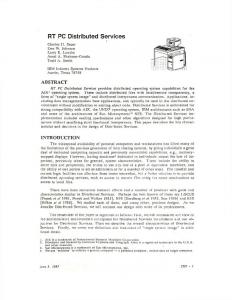
A . Hierarchical division ofpower electronics control Fig. 1. shows a way to functionally divide the control in power electronics systems. In this hierarchical architecture, the control software is divided into 3 hierarchies-high-level control, application manager (AM) and hardware manager (HM). The division is based on functionality. The high-level control performs tasks at the system level, such as responding to users’ commands, coordinating performances between converters, and monitoring system execution, etc. An AM is a controller at the converter level. It calculates control information-for example, PWM commands-for a converter. An HM is a controller at the PEBB level. The HM for a PEBB generates PWM pulses to control switch operations, according to the control information received from the AM, monitors the status of a PEBB, and performs fast protection within a PEBB. I
urcr
c13
Fig. 1. Plug and Play power electronics system architecture
This work was supported primarily by the ERC Program of the National Science Foundation under Award Number EEC-9731677.
0-7803-6618-2/01/$10.00 0 2001 IEEE
I12
The purpose of drawing boundaries between herarchical levels is to make each level as functionally self-contained as possible, and make higher level application software as independent of lower level hardware as possible. Next, we will take AM-HM levels as an example to show how to draw boundaries between levels.
B. Functional division between AM and HM For AM-HM levels, the control algorithm of a converter is application specific, and generating pulses for switches is directly dependent on features of the power stage hardware. Roughly, the software division between AM and HM can be drawn in such a way that the AM level implements the converter control algorithm, the HM level generates switch pulses, and the interface of AM-HM levels translates PWM commands into switch PWM pulse related information. However, how to draw the software boundary between AM - HM levels accurately, for example, where a modulator should be implemented, has more than one solution. The boundary drawing can be arbitrary, which means functions implemented at each level and data transferred between hierarchies are well defmed, no matter what kind of hardware is used at each level. A better solution allows boundaries float somewhat between different systems and applications, so that higher system flexibility can be achieved. For example, if the HM has enough calculation capability, some calculation can be shifted to the HM level. Thus the workload of the AM can be reduced, while the HM can be more efficiently used. On the contrary, if the HM is as simple as a logical circuit of some data buffers and timers, the AM should take over the calculation work as much as possible. The data transferred through each interface will vary with the floating of software boundaries. If the boundary floating is achieved by software instead of hardware, this method of interface definition will make the system structure more flexible and open without additional hardware requirement.
Input Output
I
Parameter Field O p e r a t i o w Exception Code Handler \ Fig. 2. Structure of power electronics control software object.
Fig. 3. shows an example of a current regulator object. From the outside of the object, what known is this object works as a current regulator, takes d channel current reference, q channel current reference, d channel current and q channel current as input, outputs voltages references for d and q channels. How the regulator is implemented is invisible to the outside.
T idref--!-+(?
-
parameter
\
compensator
vd
id
parameter
Fig. 3. An object example: current regulator.
Using object-oriented software structure can also benefit the reliability of software, which will be discussed later in section IV.
111. MODULARIZE POWERELECTRONICS CONTROL SOFTWARE BY OBJECT-ORIENTED TECHNOLOGY Another important goal of the PEBB-based PnP power electronics systems design is to modularize and standardize power electronics control software, hence make construction, debugging and maintenance of the control software much easier. In computer research, object-oriented technology [5] is a main method to achieve software modularization and reduce software complexity. Fig. 2. shows the structure of a power electronics software object. Each object has a well-defined interface, a parameter field, inside code and exception handler. The interface indicates the communication with other objects, such as inputs, output and data format. The interface also defines the function that the object provides. The inside code implements the function of the object, with implementation of code invisible to the outside. The parameter field stores parameters that may affect or direct the execution of the object, such as
Function
Interface
Iv. TIMER WATCH DOGAND EXCEPTION HANDLING MECHANISMS Two other important issues about building reliable control software will be discussed in this section: ensuring that all the time constraints can be satisfied, and protecting the system from exceptions. Power electronics systems are hard real-time systems. The correctness of a result does not only mean that the value of the result is correct, but also means that the result must be achieved before some time deadline. If the AM embedded code is stuck for some unknown reason-for example, the code cannot return from a interrupt service routine (1SR)the AM should also give out some converter control information instead of losing control of the converter. For a critical system performance, a time limit will be set. If the time for this performance expires, and the performance is not finished as expected, then the watch dog timer for the performance will force the performance to end. And some
773
reasonable but possibly not accurate results will be given out to keep the converter running. Object-oriented software offers a method of exception handling at the object level. Each software object has an exception handler to deal with exceptions raised within the object. Only if there is an exception that-cannot be handled inside the object, will this exception be propagated to the caller of the object. The purpose is to reduce the effect of an exception withm an object to the outside as little as possible.
Converter real-time control subsystem
.................................................................................................................. ............................
1 (Drivalnstaller] ConfigurationManager
V. SOFTWARE STRUCTURE DESIGN OF AM
............................................................................................
F
So far the hierarchical division of power electronics control software has been discussed. This section presents the software design of AM, which implements control at the converter level.
Information Disoatcher
I P :
E
'
0 S
i
1
Fig. 4. Software structure of AM.
A. Sofmare structure of AM
B. Configuration Manager
Traditionally, converter control means when the converter is running, the controller should generate proper control commands every switching period, make sure that all computations meet their deadlines, and handle certain exceptions. This is the type of control that AM must perform at the running time. To do PnP at the AM-HM level requires additional hnctionality at AM. Before the AM can control HMs, the AM must configure the lower level components according to both application requirements and lower level hardware specifications, which is called converter configuration. To support PnP at AM-HM levels, an HM should be able to provide the self-identification information to the AM, and accept the system resource assignment from the AM. When the system starts up, the AM should have the ability to get PEBB hardware specifications from HMs, and configure HMs in such a way that the requirements of the specific applicatio-n can be satisfied. Also the AM should be able to assign system resources, such as addresses and data buffers, to HMs without any conflict. So besides implementing the converter control algorithm, the AM should also provide some basic system services for PnP configuration, and handle interfaces to other levels. Normally, these functions are implemented by operating system in computer systems. Similarly, an embedded operating system dedicated for power electronics systems, named power electronics operating system (PEOS) is introduced. The whole control software systems at AM are composed of two subsystems: converter real-time control subsystem and PEOS, as shown in Fig. 4. The- converter real-time control subsystem can be seen as an object, and is application specific. A converter real-time control object is invoked once every switching period. It may have many sub-objects, such as sensor reading, filters, regulators, etc. Different software object combinations implement different applications. While the embedded realtime PEOS provides basic system services, such as system configuration, system resource allocation and maintenance,
In the PEOS, an object named configuration manager (CM) handles the converter PnP configuration. As shown in Fig. 4., the CM is composed of three components: the device detector, the driver installer and the device registry. The device detector searches the AM-HM network for HM that has not been configured, and assigns unique address to newly detected HM. The driver Installer installs a software dnver for a newly detected HM. The device registry is a database, which contains the driver information of all HMs controlled by one AM. The CM has two primary functions: to provide the software interface through which configuration information can be exchanged between the AM and HMs; to coordinate between the device detector, the device installer and the device registry. C. Drivers
To build open communication between levels, the concept of driver will be introduced. A driver, in computer terminology, is defined as a set of functions that manipulates a hardware device [ 6 ] . In AM-HM levels, a dnver is implemented as software objects, which are used by the AM to communicate with a specific HM. In a traditional centralized digitally controlled power electronics system, the designer of the application software must know every detail about U 0 ports, the data format of the converter controller and power stage interface in order to build up the communication between the controller and the power stage. Even small changes in the hardware setup will cause a lot of modifications in the control software. By using a driver, all the hardware specifications and communication details will be encapsulated within the driver, so that the application can be independent of the infrastructure of other levels. It has been mentioned in section I1 that floating boundary definition helps to build flexible and open systems. To support floating boundary, the format of data, instead of the content of data, exchanged between levels should be defined. The data packet format at the AM-HM interface is shown in Fig. 5. In the packet head, Packet-Type indicates the type of
774
B. PnP configuration design Fig. 7. shows the PnP configuration mechanism of the Configuration Manager, based on PES-Net. Device Detector
Message arrives? Packet-Type
Src-Addr
Dest-Addr
Length
* Driver-Installer
A PE66-IDNT packet?
No
4
J
Get Device-Name and Device-lD
A Sys-ConfigReg packet?
J
Yes Convener configuration ends
Install driver
J
4
Return to Main program
D. Information Dispatcher
Register the Device-ID, Device-Name and the beginning address of the driver installed to the Device-Registry
Fig. 7. Flow chart of Configuration Manager (CM).
Normally the results from the converter real-time control are for a whole converter. While each HM needs control information specific for its PEBB. Information Dispatcher is such a software object, which decomposes the converter related control mformation into control information for each PEBB. Further, a driver translates the control information into the format that can be understood by its corresponding HM. With Information Dispatcher and drivers, the control algorithm can really be independent of the hardware at the PEBB level. VI. A PEBB-BASED PLUGAND PLAYTHREE-PHASE INVERTER
DESIGN In this section, a three-phase inverter will be presented as an example to show the implementation of the system control software on the software architecture and software technologies discusses above. A. System architecture Fig. 6. shows the system architecture. AM-HM level communication is through PES-Net [7], which is optic fiber serial link, with transmission capacity of 125Mbps.
optic Fiber-
comniunicatton
i ' chipset
Fig. 6. System architecture of PEBB based PnP DC-AC converter.
775
When the converter configuration begins, the device detector broadcasts a system configuration request to the AM-HM network. Fig. 8. shows the data format of a system configuration request packet. Head Packet-Type Sys-Config-Reql
Src- Addr 000 ... 0
I
Dest-Addr 1 1 1 ... 1
Length
I
1
Fig. 8. Data format of Sys-Config-Req packet.
The Packet-Type field indicates that this is a system configuration request. The Src-Addr field is all zeros, which is a special address stands for the AM, because for a converter configuration packet, the sender can only be the AM. The Dest-Addr is all ones, another special address, meaning the packet is a broadcast message. Every node in the network can receive this packet. The only field in the packet body is Device-ID, which contains the next available device address for a PEBB that has not been configured. When a HM receives a converter configuration packet, it will check itself first to determine whether it has been configured or not. If the PEBB has been configured, it will simply pass the packet to the next node on the network. If the HM has not been configured, it will send its selfidentification packet back to the AM. The data format of the device self-identification packet is shown in Fig 9. The only information a PEBB tells the AM is its device name. A device name is unique for each type of PEBB, which can be used by the AM to find and install a proper dnver for the PEBB.
Head
cycle into clock ticks, which can be used directly by a specific HM to generate switching pulses. For the exception handling, before the duty cycle value is output to HM driver, the validity of the value will be checked. If the duty cycle is beyond the valid range, for example, outside [0,1], the stored previous calculation result will be used as the output.
Body Device-Name
E. Experimental results Fig. 9. Data format of Device-IDNpacket
When the AM receives a device self-identification packet, the device installer will install a driver for the PEBB according to the device name it gets from the packet. And the device installation information will be logged in the device registry. The device registry is a kind of system resource and is maintained by the PEOS. It tells the converter control the code location of the driver for a specific PEBB. Each device has an entry in device registry. And each entry has three fields, as shown in TABLE 1.
The IGBT devices used in the smart PEBB are POWEREX, 1200V/300A. Fig. 11. shows the experimental waveforms under conditions: 1) DC input voltage: 200V; 2) Switching frequency: 20lcHz; 3) Current loop closed; 4) Inductive load: R = 3ohm, L = 0.3mH. Tek~SOOks/r 33 Acqs t
-
-7
-
Unstibie histogram C4 104.4 Mean v
TABLE 1 DEVICE-REGISTRY ENTRY
1
Item Name Device-ID
I
Device Name Driver-Entry
0
.,I
CO240 Pk-Pk V
Description Identification of the PEBB in the AM-PEBB network Name of the device The entry address of the driver in the memory
Fig. 1 1. Phase current and voltage waveforms
When the AM receives a system configuration request packet, it knows that all the devices on the AM-HM network have been configured. This also implies that the system configuration is finished.
In Fig. Il., Chl shows the voltage of phase A, with 200Vfdiv; Ch2 shows the phase current of phase A, with SAfdiv; Ch3 and Ch4 shows the voltage and current of phase B respectively.
D.Converter control algorithm design For this three-phase DC-AC PnP inverter application, the current loop is closed. Fig. 10. shows the inverter control algorithm implemented by software objects.
Cycle Scalar
Cycle Scalar
da
db
Cycle Scalar
dc I I 3-D Phase Leg Duty Cycle Generator
I
abc-dqo
la
I
4
Id-ref 2-DRegulator
Fig. 10. Closed loop inverter control algorithm implemented by software objects.
A “ADC Scalar” object takes sensor values as input and outputs value after scaling and offsetting. Object “abc-dqo” transforms abc coordinates to dqo coordinates. Object “3-D phase Leg Duty Cycle Generator” is the information dispatcher. And Object “Duty Cycle Scalar” transform duty
VII. CONCLUSION AND FUTURE WORK
This paper presents a novel hierarchical software structure
of PEBB-based PnP power electronics systems. In the hierarchical structure, the power electronics system control software is divided into three levels-high-level control, application manager and hardware manager. Software design issues, such as boundary definition, software modularization, exception handling, are addressed. Software design of AM is discussed in detail. A three-phase DC-AC PEBB-based PnP inverter is implemented as an example to show the implementation of the AM. Future work includes investigating more suitable software architecture for control distribution, concurrent execution and software reuse. Dataflow is a promising candidate. Also more flexible control partition method needs to look into. REFERENCES
[ 13 S. Haisler, “ The design of operating systems for small computer system,” A Wiley-Interscience Publication, 1983, pp. 18-26.
[2] G . Blair, J. Gallagher, D. Hutchison and D. Shepherd, “Object-oriented languages, systems and applications,” An Imprint ofJohn Wiley &Sons, 1991, pp.1-3. [3] J.
Kelsey, “Programming Plug and Play,” by Snms Publishing, 1995,
PP.2.
[4] T. Ericsen and A. Tucker, “Power electronics building blocks
and potentia1 power modulator applications,” IEEE Conference Record of the 23rd International Power Modulator Symposium, New York, NY, pp. p.12-15; 1998.
[5] G. Booch, “Object oriented design”, by the BenjaminKummings Publishing Company, 199 1, pp.32-37. [6] K. Hazzah, “Writing windows VxDs and device drivers”, [5] Karen Hazzah, “Writing windows VxDs and device drivers,”by RdtD books, 1997, pp.1. [7] 1. Milosavljevic, D. Borojevic., I. Celanovic, “Modularized Communication and Control Structure for Power Converters,” 8‘‘ European Conference on Power Electronics and Applications, EPE, September 1999.
777