Rayleigh-backscattered light in a single-mode optical fiber as a result of a ... a rate of temperature change of 0.014 K/s, when a 20-cm length of fiber is heated.
April 15, 1994 / Vol. 19, No. 8 / OPTICS LETTERS
593
Distributed temperature-change sensor based on Rayleigh backscattering in an optical fiber R. Rathod, R. D. Pechstedt, D. A. Jackson, and D. J. Webb Applied Optics Group, Physics Laboratory, University of Kent at Canterbury, Kent CT2 7NR, UK Received November 30, 1993
A frequency-modulated continuous-wave technique is used to detect the presence of frequency shifts in the Rayleigh-backscattered light in a single-mode optical fiber as a result of a changing temperature. The system is able to detect a rate of temperature change of 0.014 K/s, when a 20-cm length of fiber is heated. is also able to demonstrate a spatial resolution of better than 15 cm.
There is currently much interest in the development of fiber-optic-based distributed temperature sensors. The fiber itself is an excellent choice for the sensing element of a distributed temperature sensor because it is readily available in lengths of many kilometers at low cost. A number of mechanisms have been exploited to provide the required temperature sensitivity, but in all cases the positional information is recovered by time-domain analysis.1 This approach has the disadvantage that in order for one to obtain good spatial resolution very high bandwidths are required; for example, to obtain a 10-cm spatial resolution requires signal sampling at 1 GHz. Frequency-modulated continuous-wave techniques can be used to obtain good spatial resolution without the need for high-bandwidth electronics by monitoring the positional information in the frequency domain rather than in the time domain.2 As an example, if we wish to determine the position of a reflecting surface we can illuminate the surface with light from a laser source, the frequency of which is ramped linearly (chirped). If the light returning from the reflector is interfered with light from the laser, there will be a beat frequency proportional to the distance from the reflector. This frequency may be made arbitrarily low by reducing the chirp rate. Recently this idea was applied to distributed strain sensing by interfering light from a chirped laser source with Rayleigh-backscattered light in an optical fiber.3 It was shown that the position and frequency of a periodic signal could be determined. The technique does not lend itself to the recovery of quasi-static temperature or strain measurands, but in this Letter we show that a relatively small temperature gradient (0.014 K/s) on a short length of fiber (20 cm) can be located and measured. For some fire alarm applications it is the rate of change of temperature that is of interest, suggesting that this system may find useful applications, possessing as it does the potential for a much lower cost than other distributed temperature sensor systems currently under investigation. We used the experimental arrangement shown in Fig. 1. A 300-Hz serrodyne modulation was applied to the Hitachi HLP1400 diode-laser injection current 0146-9592/94/080593-03$6.00/0
The system
to cause a peak frequency excursion of 0.71 GHz.
The 820-nm coupler was prepared by having three ends polished at 200, to prevent Fresnel reflections. The fourth coupler end was spliced to 40 m of singlemode fiber, the far end of which was silvered to provide a reference beam with which the backscattered signal could interfere. The signal displayed on the spectrum analyzer consists of a series of peaks at integer multiples of the modulation frequency. The peaks are due partly to intensity modulation of the source and partly to the interference of light backscattered within the fiber with light reflected from the mirrored end. The higher-frequency peaks are associated with light scattered from points farther from the mirrored end, i.e., closer to the source. To calculate the beat frequency associated with light scattered from a position situated at a distance x from the mirrored end, we note that the phase difference between the scattered light and light reflected from the mirror is 0=
2
2xnfz
(1)
c
where fi is the optical frequency of the source, c is the velocity of light in vacuum, and n is the refractive index of the fiber. When the source frequency is increased linearly, a beat frequency fb results, given by 1 d 2b-gdt
2xn dfz = 2xn cf dt(2
I
I
analyzer
I
Fig. 1. Schematic showing the frequency-modulated continuous-wave distributed sensor setup. K 1994 Optical Society of America
OPTICS LETTERS / Vol. 19, No. 8 / April 15, 1994
594
-1.0
0.5 * Rate of change of
-0.8 -0.6 -0.4 -0.2
temperature
v
0
Frequency shift
0 0.0
0 W
0~
N
0.0
V.)
0.2
z:
0.4 0.6 0.8
. . , ,. I . . . . I ,. , .,. I . . . -
-0.5 0
50
100
150
1.0
250
200
TIME (s)
Fig. 2. Comparison of the rate of change of temperature with time and the frequency shift with time for the 5.1-cm heating element.
where f, is the peak frequency excursion of the laser light and fr is the modulation frequency of the current ramp. Discrete peaks occur as a result of the repetitive nature of the serrodyne frequency modulation. From Eq. (2) the frequency separation of 300 Hz between the peaks in the spectrum may be identified with a fiber length of 14.5 cm, which defines the spatial resolution,L8,. = c/(2nfp), of the system. The effect of an increasing temperature over a short section of fiber situated at some point along the sensing length is to cause a continual increase in the optical path length of that section, thus imposing a frequency shift on the light passing through it. The net result is that all the peaks in the spectrum above the beat frequency corresponding to the position of the temperature gradient suffer a frequency shift, whereas those below are unaffected. Given that the temperature sensitivity for typical fiber is 100 rad/(mK), 4 then the expected frequency shift 8f is ,af =2 dOL 2 r-dt
0.6
0.4 H
0.
0
I
C-) Q2 to
0.2
I
I
.:
I
0
I 0
W
0
I
0.0
rH H4 0 E-
-0.2 k
-0.4
-0.8
-0.4
0.0
0.4
FREQUENCY SHIFT (Hz)
Fig. 3. Plot of the rate of temperature change versus the Doppler frequency shift for the 5.1-cm heating element.
100L dO =
or
dt
(3)
where XL is the optical phase difference across the heated fiber section, L is the length of the section, and 0 is the temperature of the section. Initially 5.1 cm of fiber near the silvered end was heated, and a thermocouple was used to measure the fiber temperature. As the fiber was heated the temperature and the frequency shift of the frequency peak at 2100 Hz (7fr) were recorded. This frequency corresponds to a distance of - 1 m from the silvered end. It can be seen from Fig. 2 that the frequency shift follows the rate of change of temperature quite closely. We calculated the rate of change of temperature do/dt by measuring the gradient of a temperature-versus-time graph. Figure 3 shows the linear relationship between the rate of change of temperature dO/dt and the measured frequency shift. The rms deviation from linearity of these data suggests a temperature gradient resolution of better than 0.04 K/s. The gradient of the line fitted to the data is (0.58 ± 0.04) K. A similar experiment
was
conducted with a 20.4-cm heating length, giving a temperature gradient resolution of 0.014 K/s and a -39
gradient ........
.......... I..................................I..........................................
......... ........ ........ ......... ......... ....... :......... :................... :......... :
5:
A
.
0 to
of (0.16 ± 0.01) K for the line fitted to the
data. By comparison, the values calculated for the gradients from Eq. (3) are 0.62 and 0.154 K, respectively. Good agreement is apparent between the two sets of results. Finally, the 5-cm heating element was placed 1.24 m from the silvered end. The ramping frequency was set at 5 Hz, with a peak-to-peak frequency modulation of 0.49 GHz, giving a spatial resolution
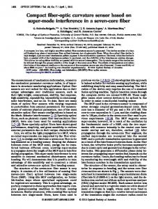
-130 L_ OHz
frequency (Hz)
Fig. 4. Plot showing frequency peaks in the detected signal. Peaks above 30 Hz suffer frequency shifts as a result of the temperature change occurring 1.24 m from the silvered fiber end.
of approximately
20 cm. A typical
trace from the spectrum analyzer is shown in Fig. 4. From Fig. 4 one can clearly see that only the sixth and higher peaks experience a frequency shift. The sixth peak is associated with a point 1.3 m along the fiber from the silvered end, showing that the position of the heat source can be correctly identified. One of the double peaks is due to the modulation of
the laser light intensity, and the other is due to the frequency shift.
April 15, 1994 / Vol. 19, No. 8 / OPTICS LETTERS
The total sensing length SL of the system, measured from the mirrored end face, is equal to CL/ 2 , where CL is the coherence length of the laser. The value of CL for the HLP1400 laser is -10 m. In conclusion, we have demonstrated a distributed sensor with a sensing length of 5 m, which is sensitive to temperature changes, has a spatial resolution of better than 15 cm, and possesses a temperature gradient resolution of 0.014 K/s when a 20-cm length of fiber is heated.
595
References 1. X. Bao, D. J. Webb, and D. A. Jackson, Opt. Lett. 18, 552 (1993). 2. R. I. MacDonald, Appl. Opt. 20, 1840 (1981). 3. R. Jugkaitis, A. M. Mamedov, V. T. Potapov, and S. V.
Shatalin, Opt. Lett. 17, 1623 (1992). 4. D. A. Jackson,
J. Phys. E 18, 981 (1985).