poses a distributed wireless network prototype, consisting of feature net and ... wireless network is very suitable for constructing a flexible face recognition ...
Distributed Wireless Face Recognition System Yanjun Yan and Lisa Ann Osadciw EECS, Syracuse University, Syracuse, NY, USA {yayan, laosadi}@syr.edu ABSTRACT A face recognition system gains flexibility and cost efficiency while being integrated into a wireless network. Meanwhile, face recognition enhances the functionality and security of the wireless network. This paper proposes a distributed wireless network prototype, consisting of feature net and database net, to accomplish face identification task by optimally allocating network resources. The face recognition technique used in this paper is subspace-based modular processing with score and decision level fusion. The subspace features are selected by a step-wise statistical procedure, Modified Indifference-Zone Method, which improves efficiency and accuracy. Fusion further improves the performance from using either the whole face or modules alone. The face recognition techniques are re-engineered to be implemented on the distributed wireless network, and the simulation result shows promising improvement over centralized recognition. Keywords: wireless, distributed, face recognition, module, subspace method, fusion
1. INTRODUCTION Face recognition includes face verification and face identification. Face verification is one-to-one matching, which has been implemented in mobile phone and personal computer login systems, by OMRON, Oki Electric, and FaceCode, etc. Face identification is one-to-many matching, where a huge database needs to be compared, and thus more challenging. It’s envisioned in the future that face identification can be also carried out with a mobile terminal interface, which captures face images and accesses face recognition processor or database through wireless network. For instance, after a policeman captures a suspect’s facial image, s/he can access the face recognition system remotely through a hand-held unit and identify the suspect on the spot. It will be more interesting if an un-manned surveillance system works independently and sends out alerts whenever somebody suspicious is in vision. The challenges in realizing this vision include: (1) A wireless face recognition system requires considerable energy, computation, and bandwidth for image acquisition, processing, and transmission. (2) Face recognition techniques need to be robust and accurate, and it should scale with the size of user group. This paper addresses the above challenges by efficiently allocating network resources in a distributed manner, and re-engineering the face recognition techniques to implement them on a wireless network. The motivation of this research is that there are many benefits from constructing a wireless face recognition system: (1) A wireless network is very suitable for constructing a flexible face recognition system, because a wireless setup incurs minimal modification to existing infrastructures, and a wireless network provides scalable and flexible monitoring region. If a wireless face recognition system has been set up, once the security level changes and the network needs to be moved, the wireless network can be moved and reused easily. (2) Face recognition enhances the functionality and security of the wireless network, whilst a face recognition system is integrated with existing systems. Face recognition provides identity and expression information for event analysis to constitute a smart environment, and face recognition can replace or concert with other security measures to enhance the security. There is some relevant work on wireless face recognition: Zaeri, Mokhtarian and Cherri discuss face recognition for wireless surveillance systems.1 Rajani and Yan propose a prioritized transmission scheme for a wireless system especially designed for face recognition.2 Ikdong, Jaechang, Jason and Wayne implement a wireless face recognition system based on ZigBee transmission protocol and Eigenface method with low power consumption.3 Though not designing for a face recognition system, Robert and Leonard propose a simulation framework and performance criteria for a distributed sensor processing over an ad hoc wireless network,4 where a model of three conceptual layers in a wireless sensor network is proposed. Based on this model, this paper proposes a distributed wireless network prototype to carry out face identification task by optimally allocating the resources within the
network. The face recognition technique used in this paper is subspace-based modular processing with score and decision level fusion, where the features are selected by statistical step-wise simulation, and the fusion results are shown to be superior to using either the whole face or modules alone.5 The rest of the paper is organized as follows. Chapter 2 reviews the face recognition systems. Chapter 3 discusses the wireless environment of distributed network. Chapter 4 provides some numerical experimental results, and Chapter 5 concludes this paper with summaries and future work.
2. REGULAR FACE RECOGNITION SYSTEM Without considering the wireless network, the diagram of the core face recognition system is shown in Fig. 1. In enrollment, the images of the registered users are processed into templates of caricatures by the specific algorithms of the face recognition system, and these templates are stored. The templates can be regarded as the transformed user images encoded by the corresponding processing techniques. The processing techniques and the templates are adjusted concurrently. In verification or identification, the face recognition system receives a new image, defines and stores the new image by the same algorithm, and compares to the templates. The decision process may incorporate all kinds of classifiers. If the classifier is a learning algorithm and its structure needs to be trained such as the neural network or Bayesian network, the enrollment database may be split into two parts, one for constructing the templates, and one for learning the classifier structure.
Enrollment Face Database
Processing
Templates
Identification Pre-Processing
Processing
Comparison
Identity
Figure 1. General Diagram of the Face Recognition System. The templates can be regarded as the transformed user images encoded by the corresponding processing techniques. The processing techniques and the templates are adjusted concurrently.
Face recognition techniques can be roughly classified into the following categories. Interested readers are encouraged to get more references from reading these provided references. • Template based: A typical template-based method is PCA (Principle Component Analysis) based eigenface method, which uses holistic information of the face. The eigenfaces are extracted from the training images.6 The face images of the people on the watch list are projected onto the eigenface space, and the coordinates are stored as templates to compare with testing images. There are other transforms based on LDA (Linear Discriminant Analysis) or ICA (Independent Component Analysis), and the templates are associated with the transforms. • Feature based: Features are descriptions or quantitative measurements of local facial features such as eyes, nose and mouth for direct comparisons.7 The local features need not to be organs, but they are meaningful objects occupying partial image. The local features segmented from the facial image do not have to be used altogether, the features can be further selected for better performance.8, 9 The features can be generalized as responses to Gabor filters etc.10, 11
• Rule based: A learning algorithm, such as support vector machine (SVM), decision tree, neural network or Bayesian network, is trained on the available dataset, which constitutes an explicit or implicit set of rules. The rules are evaluated on the testing image to reach a final decision. • Model based: The most popular models include elastic-bunch-graph (EBG) model and hidden Markov model. In EBG analysis, the bunch graph is constructed from a small set of sample image graphs. Recognition is based on a straightforward comparison of image graphs.12 In hidden Markov model analysis, the strips tessellating the facial image are assumed to be related by the hidden Markov model. In both models, the model parameters are fitted to the training images, and each subject has a distinctive model. The recognition is based on the fitting of the models. Generally in 3D face modeling and analysis, the model fitting is also essential.11, 13, 14 • Module based: Facial modules are similarly defined or detected as local features, but modules are analyzed as self-contained components.15 The features, scores or decisions from modules can be also combined together to reach a fused result.5 The fusion at both score level and decision level is shown to improve the recognition performance.
2.1 Subspace based Methods Sub-spaced methods are approximately template based methods in the sense that the projections used in deriving the templates utilize different subspaces. The training images are pre-processed, mean extracted, vectorized and paralleled to construct a single matrix, the covariance matrix of this training matrix is highly singular because the number of features is much less than the dimension of the images. PCA based Eigenface method utilizes the range space of the covariance matrix of the training database to fully represent the training data.6, 16 Within class scatter is defined as the covariance matrix of the different images of the same person. Between class scatter is defined as the covariance matrix of the differences between different subjects, where the means of different subjects are used as the representations of those subjects. LDA based Fisherface method applies PCA first to discard the null space of the within class scatter to avoid the singularity problem and then utilizes the range space of the between class scatter.17 But the null space of the within class scatter is also shown to be informative in discrimination, so Chen, et.al.18 and Yu, et.al.19 proposed direct LDA methods (D-LDA) to implement the LDA method on the original high dimensional space without the PCA reduction. However, techniques by Chen, et.al. may get intractable when the within class scatter is too big, and techniques by Yu, et.al. may suffer from the possible singularity of the within class scatter, where a heuristic constant � is introduced to control this situation, but the selection of � is subjective. Lotlikar, et.al.20 introduced the weighting functions to make the closer classes more separated in outputs, and it’s called fractional-step LDA method (F-LDA). Lu, et.al.21 combines the D-LDA method and F-LDA method, and proposes DF-LDA method, which avoids the singularity problem of the within class scatter with variation on the optimization objective to simplify the calculation while keeping the performance. DF-LDA technique is applied in this paper, which utilizes the null space of the within class scatter and the range space of the between class scatter.
2.2 Modular Recognition Besides subspace based DF-LDA technique, modular processing is also applied in this paper. The modules are segmented eyes, nose, mouth, etc., which are treated as independent objects for classification. Face recognition, as one of the non-contact, less-intrusive biometrics, is irreplaceable in certain situations. However, other biometrics may not always be feasible for multimodal biometrics. It helps to implement diversity in face recognition alone. Therefore, modules such as the eyes, mouth, nose and forehead are treated as separate biometrics, together with the whole face image, to constitute multiple classifiers for face recognition. The modules are utilized to derive the Eigenparts or DFLDAparts by the same algorithms used on the whole face. Since the images of modules are directly segmented from the whole face image, the fused result from multiple classifiers emphasizes the features existent in both the Eigenface and Eigenparts, or LDAface and LDAparts. The emphasis on these features improves identification because certain individuals have very distinguishing eyes, nose or mouth, and some local modules are not varying much as other modules of the face.
The Eigenface or Eigenparts method is based on PCA to process faces or parts, where the features are derived from the rank space of the total sample scatter. The features are representative of the gallery images, but the discrimination ability may not be optimized. The DFLDA method or DFLDAparts method is based on LDA to process the faces or parts, where the features are derived from the rank space of between class scatter and the null space of the within class scatter. The discrimination ability is optimized.
2.3 Fusion of Modular Decisions Classification based on a single image, whether it is the whole face or a part of the face, can be carried out by the same methods described in Fig. 1. Thus, we refer to processing the face or module as a single run classifier. Each classifier tries to recognize different regions of the test image. This paper fuses classification results from the local parts, but not simply concatenates the modular features. From a single test image, five similarity scores are derived for each classifier using the stored templates. The similarity scores are real numbers indicating their relative degree of similarity. The score from each classifier can be normalized and combined for a final score. Again based on the similarity scores, each classifier can decide on which subject the test image is closest to. In some applications, it is not only the most similar identity, but also the runners up that are in concern. The classifiers maintain the rankings of several potential identities. The ranking of the potential identity indices is called a decision. The final result is a categorical number. Correspondingly, the fusion of Eigenface and Eigenparts results or DFLDA and DFLDAparts results can be done at either score level or decision level. 2.3.1 Score level fusion Score level fusion utilizes the scores from each classifier to make the final decision as shown in Figure 2. The fusion center sums up the scores from all individual classifiers, and then it sorts the summed similarity scores to rank the possible identities. The summation could be weighted according to the relative accuracy and importance of each individual classifier.22 Score level fusion needs to transmit the real number scores from the classifiers to the fusion center. This takes more transmission recourses than the categorical ranking decisions from the classifiers, but the score provides more information.
Compare with template k
Registered User Templates Obtained In Enrollment
Fused Score of Multiple Biometrics
K 1
Fused Score of Multiple Biometrics
k
∑
Similarity Score
Fused Score
Sc Sco or re e
ore Sc e or c S
Find Maximum
Non-Face 1
k
K
Vary k = 1, … K
Sorted Possible Identities (I(1), … , I(K) )F
Figure 2. Score Level Fusion of face and parts
2.3.2 Decision level fusion Decision level fusion utilizes decisions from each classifier to form a final decision as shown in Figure 3. The fusion center receives several most probable identities from each classifier, and then these decisions go through a majority voting machine to rank the possible identities.
Now that there are five individual classifiers: one from the face, four from the modules, and each classifier can be switched on and off, there are 25 possible schemes to utilize the available classifiers. Majority voting is utilized in this paper to make use of all available classifiers. Decision level fusion greatly reduces bandwidth needs on transmission. However, once the decision is made at each classifier based on the scores, the information on their relative degrees of similarity is lost preventing its use in the final decision. Score of one biometric
1
k
K
Score of one biometric
Sorted Possible Identities (I(1), … , I(K) )1
(I(1), … , I(K) )2 (I(1), … , I(K) )
3
Voting Machine
(I(1), … , I(K) )F
(I(1), … , I(K) )4 (I(1), … , I(K) )5
Figure 3. Decision Level Fusion of face and parts
The score level fusion needs the similarity scores from each classifier. The classifiers based on the modules are weaker than the classifier based on the face.5 Variations based on different weighting of the five classifiers are tried. If the weaker classifiers (either one or more of the Eigenparts result) are weighted more, the final recognition rate decreases; If the face classifier (the Eigenface result) is weighted more, the fused result is closer to the Eigenface result alone. When the five classifiers are weighted equally, the recognition rate improves dramatically by over 10.3% from recognizing the whole face or modules alone.5 Decision level fusion needs the ranking of the indices of the possible identities from each classifier, but is still capable of improving performance by 9.4% from recognizing the whole face or modules alone. The indices in the ranking are categorical integers, which requires less storage and less transmission bandwidths than the similarity scores used in score level fusion.5
3. WIRELESS FACE RECOGNITION SYSTEM Currently the wireless networks suitable for wireless face recognition system include mobile ad hoc network (MANET) and distributed wireless sensor network. The network topology and routing protocols of MANET and wireless sensor network differ, and they work in different scenarios. The wireless channels between the nodes are modeled as slow Rayleigh fading. The path loss is neglected here because the wireless face recognition system is usually distributed in a relatively small local area. Hence, the variation of such a wireless network is mainly due to the small scale fading. An agent based routing protocol improves packet delivery rate (the percentage of delivered packets from source to destination) and BER (the bit error rate of received packets) over the standard routing protocol,23 and is implemented in this paper.
3.1 MANET (Mobile Ad-hoc Network) MANET is implemented as WLAN (wireless local area network) or WPAN (wireless personal area network). WLAN is based on IEEE802.11 (with subgroups in b, g, a, h, etc). WPAN is based on IEEE802.15, such as Bluetooth (IEEE802.15.1) and ZigBee (IEEE802.15.4). WPAN consumes less power than WLAN, but covers less area. Depending on the hardware setup, either WLAN or WPAN can be utilized. If both WLAN and WPAN are available in the same coverage, the network in use is selected by which one provides a healthy link with less energy consumption and less hops etc. at the instance. MANET is used in the scenario of limited terminal units. The terminal units are connected to WLAN or WPAN for a finite duration, and the nodes within this network form an ad hoc network. The nodes self-organize
themselves and enable the communications between the terminal units, processors and database. The processing can be done in parallel by several processors, and the database can be stored distributedly. An example of such scenarios is that a policeman captures a facial image, and then he can access the face recognition system remotely through a handheld unit and identify the suspect right on the spot, yet the policeman does not have to know how the identification is done. The terminal units are the source nodes providing the testing image, and the processors are the sink nodes to compare the transformed testing image with the templates transmitted from the database. Once the identification task is finished, the terminal units withdraw from the network, and the links among terminal units, processors and database are expired to protect the security of the system.
3.2 Distributed Wireless Sensor Network The sensors in a distributed wireless sensor network are deployed with specified topology or a statistical distribution. Such a network can be set up in any region of interest with more flexibility. However, the sensors in a sensor network are usually small in size, modest in battery and power, limited in bandwidth, short in memory, and low in processing ability, which impose strict constraints on such a network. A wireless sensor network is deployed for a specific task, usually in the scenario of monitoring a region without definite source nodes as in MANET. The sensor nodes take measurements, detect facial images, and communicate with each other to reach a conclusion on detection, and then the face images from the detection are transmitted towards the processors. If the identification task is very specific on a limited number of identities, the processing can be implemented within the network spending limited resources; otherwise, a sink node of the network acts as a gateway to another network with processors and database. The routing protocol for a wireless sensor network is crucial to preserve energy of the network, minimize the delay in transmission and maximize the packet delivery rate. A swarm intelligence based cognitive routing protocol is shown to perform robustly under attacks and jamming,23 and it is utilized in this paper. In wireless sensor network, the detection of a face image is the first step, and such detection and possibly subsequent tracking can be cooperated by several sensors. In face detection, it’s the common features of all the faces that are used for detecting the face. Several popular face detection techniques are listed below. 1. Correlation or template-matching based detection, such as by Kah and Poggio.24 Depending on the template used in correlation, this method may lose robustness. There have been constant improvements on template extraction, such as utilizing PSO (Particle Swarm Intelligence) in generating a directional map based template25 by Claudio A. Perez etc. recently, which works better than Component Maximization method. 2. Neural Network based face detector, such as by Rowley, Baluja and Kanade26 and Curran etc.27 The images are fed into the neural network to compare the images with remembered patterns. 3. Aggregated Bayesian-network-classifiers based face detector, such as by Thang V. Pham et. al.28 Many random images are generated from each training image by random rotation, scaling and flipping to ensure the training of the Bayesian network. 4. Support Vector Machine based face detector, such as by Stan and Zhang,29 Waring and Liu,30 and Li et. al.31 5. Viola-Jones face detector,32 where boosting, or its adaptive variations, such as Ada-Boost33 and FloatBoost34 are implemented. This is the most popular face detector, and the boosting is also used widely in image retrieval and other pattern recognition tasks. Presently, face tracking techniques are implemented in our daily life. For instance, there are many highend webcams with built-in features of automatic face tracking and automatic focus, such as the Orbit, Fusion and Pro series from Logitech QuickCam, and the WebCam Live! series from Creative. Even with a common lower-end webcam, there are software products that can realize the automatic face tracking features, such as the CamTrack from DigitalPeers.com, Webcam Monitor Surveillance Software, or EyeCopia. A camera sensor with face detection ability can be readily utilized in a face identification sensor network. The camera sensor is attached to a transmitter to transmit the segmented face image and communicate with other nodes in the sensor network.
3.3 Distributed Processing of Face Identification By either MANET or a wireless sensor network, the transmitted face images are processed in parallel and compared with the distributed database. This section discusses the distributed operation of DF-LDA algorithm and the fusion of modular processing results for face identification within such a distributed network. In DF-LDA algorithm, the training database is used to learn the between class scatter Sb and within class scatter Sw . The images used in training should include the subjects of interest and many general subjects to fully explore the feature space in identification. Lu, et.al.21 and Lotlikar, et.al.20 propose a refined definition of between class scatter Sb by putting more weight on closer samples for better separation of them in classification. The new definition is denoted as Sˆb , Sˆb =
c X
nk ·
k=1
c X
w(dkl ) · (µk − µl ) · (µk − µl )T ,
(1)
l=1,l6=k
where w(dkl ) is the weight determined from the Euclidean distance between the means of the two classes k and l, dkl = kµk − µl k. The weighting function is usually a monotonically decreasing function such as w(d) = d−q to weigh more on the closer classes since they are more difficult to classify. w(d) should drop faster than (µk − µl )(µk − µl )T , and hence q ≥ 3 is used. Meanwhile, the distance between the same mean images is zero thus the weight is infinity, preventing the identification of close yet different images. Therefore, the image comparison is done only between different subjects. The within class scatter is defined as Sw =
ni c X X
(ai,j − µi )(ai,j − µi )T ,
(2)
i=1 j=1
where c is the number of subjects in database, or c classes that we want to classify. There are ni images for each subject i ∈ [1, c]. ai,j is the jth face image vector for the ith subject. µi is the average image vector for the ith subject. The optimization function used in DF-LDA is ΦDF −LDA = arg max Φ
ΦT Sˆb Φ ΦT Sˆb Φ + ΦT Sw Φ
= arg max Φ
ΦT Sˆb Φ , ΦT Sˆt Φ
(3)
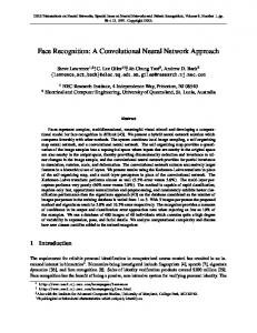
where Sˆt = Sˆb + Sw is a modified total scatter. DF-LDA method finds Sˆb,range first, projects Sˆt onto it, and finds the features to maximize ΦT Sˆb,range Φ, since Sˆt is nonsingular. The projection, or the matrix of features used in DF-LDA, ΦDF −LDA , is derived in enrollment, which can be done off-line. For each subject in interest, his/her face image is projected to construct his/her template. The template consumes less storage than the original image, and it’s the template that is stored in the database. In identification, the testing image is projected onto ΦDF −LDA to derive a testing template, and then the testing template is compared with the templates within the database to see whether there’s a similar match. A wireless network to carry out face identification task should optimally allocate the resources within the distributed network. The resources currently in consideration are sensor energy, transmission bandwidth, buffer size or memory, and the processing ability. Energy preservation can be taken care of by a swarm intelligence based routing protocol,23 other parameters by can take care of by parallel processing. The projection in deriving the template of the testing image (the detected face image) is an inner product of the testing image with the features in the projection matrix. Depending on the capacity of the nodes, the features are stored in parallel in a net of nodes, either one feature in one node, or a few features in one node. The net of nodes storing features is named as feature net. Whenever a testing image comes in, the source node broadcasts this image to the nodes in the feature net. The nodes in the feature net need to do only one or a few inner products. The outputs of the feature net constitute the template of the testing image. The template of the testing image is again broadcasted to a net of database nodes. Depending on the node capacity, each database node stores one or a few comparing templates. The comparing templates are from the people that the system has already known. The net of nodes storing database is named as database net. Once the template of the testing image is broadcasted to the database net, on each node, the similarity score is calculated between
the testing image and the stored identity. An agent based searching algorithm randomly searching through the database net to select the best match. The matching result is either communicated back to the terminal unit, or, another GUI of such a wireless face recognition system. Feature net and database net are conceptually separate, but they can be physically overlapped. Feature net is shown in Fig. 4, where the left shaded red node is source node, which collets the testing image and broadcasts it to the feature net. The right shaded green node is sink node, which collects the outputs from the feature nodes. The outputs from the feature nodes form a vector, which is the template of the testing image. Feature nodes are the numbered nodes, which do the inner product of the testing image and the features. The number of the feature net nodes is the index of features. The other empty nodes are idle for now, but they are backup nodes of the network. The idle nodes become active while the subject is moving, or some current feature nodes stop meeting the energy requirement to serve as feature nodes. While the subject is moving around the network, the source node is moving along, and the new nearby nodes form an updated feature net. The features are copied from the original feature net to the updated feature net. The sink node of feature net serves as a gateway to the database net. Source node. Sink node. 2
#
Feature net nodes. Idle nodes.
1 3
N
4 5
Figure 4. Conceptual diagram of a feature net. Inner product is carried out at each feature net node between incoming image vector and stored feature vector.
Database net is shown in Fig. 5, where the right shaded green node is source node, which is exactly the same sink node in feature net. The source node broadcasts the template of the testing image to the database net. The checker shaded cyan node is sink node, which can be an outside GUI or the original terminal unit. Namely, physically, the sink node of the database net could be the source node of the feature net. Database nodes are the numbered nodes, which do the inner product of the template of the testing image and the templates of the known subjects. The number of the database net nodes is the index of subjects. The outputs from the database nodes are the similarity scores of the testing image to the known subjects. In order to optimize the searching, multiple maximum searching agents are deployed in the database net to collect possibly big similarity scores. Not all outputs of the database nodes need to be sent to the sink nodes, and several links are omitted intentionally. The other empty nodes are idle for now, but they are backup nodes of the network. Once the feature net and database net are defined for one module for face identification while minimizing the energy consumption and other link resources, other modules can utilize the same routing table in feature net to implement the parallel processing. The searching results for different modules usually differ, but the outputs sent from the same database node for different modules definitely enhances the possibility that this database node is the true identity, and the score level fusion and decision level fusion can be implemented in the sink node of the database net.
Source node. Sink node. #
Database net nodes. Idle nodes.
1 3 2 4 c 5
Maximum searching within
Figure 5. Conceptual diagram of database net. Only the responses stronger than a threshold are sent to the sink nodes representing potential subjects. Not all outputs of the database nodes need to be sent to the sink nodes, and several links are lfet open intentionally.
4. EXPERIMENT RESULT The feature net and database net are both constructed with simple sensor nodes, whose processing task is mainly to calculate inner products or differences between the incoming signal and the memorized signal. In the training for feature extraction, the features are selected off-line by Modified Indifference-Zone Method35 (MIZM). MIZM is based on computer simulated distribution of features as a pragmatic metric to determine the confidence interval of feature number by a step-wise statistical procedure. The reasons to resort to computer simulation to derive the pragmatic feature distribution are two-folded: (1) The asymptotic distribution deviates from the true distribution when the sample size is limited. (2) The empirical distribution is very hard, if not impossible, to derive due to the variations of the population. After the features are extracted, each feature is stored in a single feature node. It is possible that if the nodes are more powerful in processing ability and memories, they can store more features. Or if the number of feature nodes are limited, each node needs to store more than one features. The nodes storing more than one features can be treated as an aggregation of several simple nodes. Conceptually, each node is associated with a single feature. The outputs of feature nodes are collected by a gateway node to fill in a new vector, the projection of testing face onto the feature space. In face identification, the templates are distributed in database net. The projection of the testing image is compared with each template at associated database node. If the inverse of the distance, the similarity score, is larger than a threshold, which means that the two images are very close, the similarity scores are fed-back to the administrator of the wireless face recognition system. Because only the templates close to the testing images are fed-back, many links between the database node and administrator node are left open, which saves transmission resources. A simulation on the distributed feature selection and template comparison is implemented on FERET database. Face identification based on MIZM selected features and efficient transmissions are denoted as “MIZM method”. The “Scree method” selects features by heuristics, which may not be consistent for all databases. The “All method” is a bench-mark for comparison by using all the features. The log scale ROC (receiver operating characteristic) curve is shown in Figure 6, where the margin between MIZM (the solid line) and Scree method (the dashed line) is consistent. ROC illustrate the relative relationship between F AR and F RR for all possible thresholds. The CMS (cumulative matching score) plot is shown in Figure 7, where the MIZM method (the solid line) achieves better recognition result earlier along the rank axis. CMS plot provides rank-k results. Rank k means that the true identity is within the first k candidate identities provided by the face recognition system. Rank-k result is particularly useful when face recognition is used for automatic screening, where further identification by other methods is carried on.
ROC (Receiver Operating Characteristic) on FERET database 1
0.9
0.8
Recognition Rate
0.7
0.6
0.5
0.4
0.3
0.2
0.1
MIZM Scree All
0 −4 10
−3
−2
10
10 Fale Acceptance Rate (in Log scale)
−1
0
10
10
Figure 6. Log scale ROC curve of performance comparison on FERET database CMS (Cumulative Matching Score) on FERET database 100
90
80
Recognition Rate
70
60
50
40
30
20
10
0
MIZM Scree All 50
100
150
200
250 Rank
300
350
400
450
500
Figure 7. CMS curve of performance comparison on FERET database
5. CONCLUSIONS Face verification has been realized in commercial products, but face identification is still a challenging task. This paper utilizes a robust face recognition technique, DF-LDA, together with Modified Indifference-Zone Method for feature selection, and modular processing for performance improvement by fusion, to carry out face identification task. This paper also proposes a wireless system model, consisting of feature net and database net, for distributed face identification based on MANET or a wireless sensor network. The resources of the wireless network are optimally allocated under the strict constraints of the network, such as energy, bandwidth, and channel uncertainties. With the efficient and effective feature selection, face identification performance is superior to heuristic feature net construction or brute-force usage of all features.
REFERENCES 1. N. Zaeri, F. Mokhtarian, and A. Cherri, “Efficient face recognition for wireless surveillance systems,” in Computer Graphics and Imaging, CGIM 2007, E. Gobbetti, ed., pp. 553–037, OACTA Press, Innsbruck, Austria, 2/13/2007 - 2/15/2007. 2. Y. Yan, R. Muraleedharan, and L. A. Osadciw, “Ant system based flexible and cost effective routing for wireless face recognition,” (Las Vegas, USA), 2008. 3. I. Kim, J. Shim, J. Schlessman, and W. Wolf, “Remote wireless face recognition employing zigbee,” in Workshop on Distributed Smart Cameras (DSC 2006), in conjunction with ACM SenSys 2006, (Boulder, CO, USA), October 2006. 4. R. E. V. Dyck and L. E. Miller, “Distributed sensor processing over an ad hoc wireless network: simulation framework and performance criteria,” in Military Communications Conference, 2001. MILCOM 2001. Communications for Network-Centric Operations: Creating the Information Force. IEEE, 2, pp. 894 – 898, Oct. 2001. 5. Y. Yan and L. A. Osadciw, “Fusion for Component based Face Recognition,” in Proceedings of CISS 07, (Johns-Hopkins University, Baltimore, Maryland, USA), March 2007. 6. M. Turk and A. Pentland, “Eigenfaces for recognition,” Journal of Cognitive Neuroscience 3(1), pp. 71–86, 1991. 7. R. Brunelli and T. Poggio, “Face recognition: Features versus templates,” IEEE Transactions on Pattern Analysis and Machine Intelligence 15, pp. 1042–1052, October 1993. 8. B. Heisele, P. Ho, and T. Poggio, “Face recognition with support vector machines: global versus componentbased approach,” in Computer Vision, 2001. ICCV 2001. Proceedings. Eighth IEEE International Conference on, 2, pp. 688 – 694, July 2001. 9. B. Heisele, P. Ho, J. Wu, and T. Poggio, “Face recognition: component-based versus global approaches,” Comput. Vis. Image Underst. 91(1-2), pp. 6–21, 2003. 10. B. S. Manjunath, R. Chellappa, and C. V. D. Malsburg, “A feature based approach to face recognition,” in Proceedings of IEEE Computer Society Conference on Computer Vision and Pattern Recognition, pp. 373– 378, 1992. 11. J. Cook, V. Chandran, S. Sridharan, and C. Fookes, “Gabor filter bank representation for 3d face recognition,” in DICTA ’05: Proceedings of the Digital Image Computing on Techniques and Applications, p. 4, IEEE Computer Society, (Washington, DC, USA), 2005. 12. L. Wiskott, J.-M. Fellous, N. Kr¨ uger, and C. von der Malsburg, “Face recognition by elastic bunch graph matching,” in Proc. 7th Intern. Conf. on Computer Analysis of Images and Patterns, CAIP’97, Kiel, G. Sommer, K. Daniilidis, and J. Pauli, eds., 1296, pp. 456–463, Springer-Verlag, (Heidelberg), 1997. 13. H. Schneiderman, A Statistical Approach to 3D Object Detection Applied to Faces and Cars.PhD thesis, Robotics Institute, Carnegie Mellon University, Pittsburgh, PA, May 2000. 14. Y. Sun and L. Yin, “A Genetic Algorithm Based Feature Selection Approach for 3D Face Recognition,” in The Biometric Consortium Conference, (Hyatt Regency Crystal City, Arlington, Virginia USA), September 2005. 15. A. Pentland, B. Moghaddam, and T. Starner, “View-based and Modular Eigenspaces for Face Recognition,” in Proc. of IEEE Conf. on Computer Vision and Pattern Recognition (CVPR’94), (Seattle, WA), June 1994. 16. H. Hotelling, “Analysis of a complex of statistical variables into principal components,” Journal of Educational Psychology 24, pp. 417–441, 498–520, 1933. 17. P. N. Belhumeur, J. P. Hespanha, and D. J. Kriegman, “Eigenfaces vs. fisherfaces: Recognition using class specific linear projection,” IEEE Trans. Patt. Analy. Mach. Intell. 19, pp. 711–720, Jul. 1997. 18. L. Chen, H. Liao, M. Ko, J. Lin, and G. Yu, “A new LDA-based face recognition system which can solve the small sample size problem,” Pattern Recognition 33, pp. 1713–1726, 2000. 19. H. Yu and J. Yang, “A direct LDA algorithm for high-dimensional data with application to face recognition,” Pattern Recognition 34, pp. 2067–2070, 2001. 20. R. Lotlikar and R. Kothari, “Fractional-step dimensionality reduction,” Pattern Analysis and Machine Intelligence, IEEE Transactions on 22, pp. 623–627, June 2000.
21. J. L. K. N. Plataniotis and A. N. Venetsanopoulos, “Face recognition using LDA-based algorithms,” IEEE Trans. on Neural Networks 14, pp. 195–200, JANUARY 2003. 22. K. Veeramachaneni, L. Osadciw, and P. Varshney, “An adaptive multimodal biometric management algorithm,” Systems, Man and Cybernetics, Part C, IEEE Transactions on 35, pp. 344–356, Aug. 2005. 23. R. Muraleedharan, Y. Yan, and L. A. Osadciw, “Constructing an efficient wireless face recognition system by swarm intelligence,” in AGEP Academic Excellence Symposium, Syracuse University, Syracuse, NY, 2007. 24. K.-K. Sung and T. Poggio, “Example-Based Learning for View-Based Human Face Detection,” IEEE Trans. Pattern Anal. Mach. Intell. 20(1), pp. 39–51, 1998. 25. J. I. V. Claudio A. Perez, “Face detection using pso template selection,” in Int’l Conf. on IEEE Systems, Man and Cybernetics, p. 5, (Taipei, Taiwan, China), 2006. 26. H. Rowley, S. Baluja, and T. Kanade, “Neural network-based face detection,” IEEE Transactions on Pattern Analysis and Machine Intelligence 20, pp. 23–38, January 1998. 27. K. Curran, X. Li, and N. Mccaughley, “Neural network face detection,” Imaging Science Journal, The 53, pp. 105–115, June 2005. 28. T. V. Pham, M. Worring, and A. W. M. Smeulders, “Face detection by aggregated bayesian network classifiers,” Pattern Recogn. Lett. 23(4), pp. 451–461, 2002. 29. R. Xiao, M. Li, and H. Zhang, “Robust multi-pose face detection in images,” IEEE Transactions on Circuits and Systems for Video Technology 14, pp. 31–41, Janurary 2004. 30. C. A. Waring and X. Liu, “Face detection using spectral histograms and svms,” Systems, Man and Cybernetics, Part B, IEEE Transactions on 35(3), pp. 467–476, 2005. 31. Y. Li, S. Gong, J. Sherrah, and H. Liddell, “Support vector machine based multi-view face detection and recognition,” Image and Vision Computing 22, pp. 413–427, May 2004. 32. P. Viola and M. J. Jones, “Robust real-time face detection,” International Journal of Computer Vision 57(2), pp. 137–154, 2004. 33. Y. Freund and R. E. Schapire, “A short introduction to boosting,” Journal of Japanese Society for Artificial Intelligence 14, pp. 771–780, September 1999. 34. S. Z. Li and Z. Zhang, “Floatboost learning and statistical face detection,” IEEE Transactions on Pattern Analysis and Machine Intelligence 26, pp. 1112–1123, September 2004. 35. Y. Yan and L. A. Osadciw, “Feature selection for wireless face recognition sensor network,” in Proc. 7th IEEE Upstate New York Workshop on Communications, Sensors and Networking, (Syracuse, NY), Nov. 2007. Sergio Servetto Memorial Best Student Poster Award.