Diversity- and AMC (Adaptive Modulation and Coding)-Aware Routing in TDMA Multihop Networks S. Hares, H. Yanikomeroglu, and B. Hashem* Broadband Communications and Wireless Systems (BCWS) Centre Dept. of Systems and Computer Engineering, Carleton University, Canada *Saudi Telecom Company, Saudi Arabia {shares, halim}@sce.carleton.ca,
[email protected] Abstract – Multihop relaying in TDMA networks can provide significant gains in network throughput and reduce outage probability. Diversity schemes such as multihop maximal ratio combining can be used in networks to increase throughput without consuming additional radio resources. This paper presents novel diversity- and AMC (adaptive modulation and coding)aware routing algorithms that result in significant throughput gains and outage reductions without requiring additional resources. An important observation is the need for mixed analog and digital relaying to enhance performance when using multihop maximal ratio combining. I.
INTRODUCTION
Recently there has been increasing interest in the concept of augmenting the infrastructure-based networks with multihop communications capability in order to provide high data rate coverage in large areas in a cost efficient manner [1]. Multihop communications can be facilitated through lowcomplexity fixed relays (wireless router) deployed by the service providers or through other wireless terminals in the network (peer-to-peer relaying). This paper is on multihop peer-to-peer communications in TDMA TDD networks which use AMC, and it builds on our recent work published in [2]. A number of routing algorithms are presented with the goal of increasing the network throughput without consuming any additional time resources due to relaying. The novelty in these routing algorithms is that they choose the routes to take advantage (in various ways) of both the AMC signaling and the naturally created multiple paths in the form of diversity. Both digital and hybrid analog digital relaying schemes are considered for diversity. A HiperLAN/2 network is considered in the simulations due to its centrally controlled network architecture and the extendibility of its MAC protocol for relaying [3]. The simulation results indicate that the diversity- and AMCaware routing algorithms introduced in this paper yield substantial throughput increase and outage reduction. II.
AMC AND RELAYING
AMC efficiency and frame segmentation are key factors in selecting routes to maximize throughput in TDMA systems. Relaying in TDMA systems requires time slots used to
transmit original information to be used to relay data; we term this effect frame segmentation. However, throughput may be increased via relaying if the route provides a lower error rate and increased AMC efficiency. A.
AMC Efficiency Networks using AMC can increase or decrease efficiency by selecting an AMC level (mode) denoted by m. AMC allows a link to be adapted such that the throughput is maximized for channel conditions. The mode for a link or hop i can be selected by,
m i(max) max (D i −1, i (m i −1, i ) ⋅ (1 − Pe ( SNRi −1, i , m i −1,i ) )) . −1, i = arg
(1)
m∈M
Here m i(max) is the mode from the set of all modes, M, which −1, i maximizes the throughput for the link between nodes ri-1 and ri. AMC efficiency, Di-1,i in bits/symbol, is a function of mode. Relaying networks use AMC to select hop modes to take advantage of diversity and maximize connection (source to destination) throughput.
B.
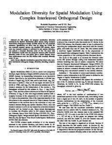
Relaying and Frame Segmentation Depending on the volume of traffic, the access point (AP) schedules a number of time slots per connection per frame. A connection’s time slots are further divided for relaying where each segment corresponds to a hop in the route. Additional time slots are not used for relaying. Let us consider the generic relaying scenario with n hops shown in Fig. 1, where the 0 ’th node in the route, r0, represents the source, node rn represents the destination, and nodes r1 through rn-1 represent relaying nodes according to the order of the route. Ingress and egress traffic volumes at relaying nodes are equal. Then the following expression [2] is used to divide a frame into segments for an n-hop connection, si −1,i =
n
S , Di −1,i
∑D j =1
i ∈ {1, K , n − 1} .
(2)
j −1, j
Expression (2) implies that for the i’th hop between nodes ri-1 and ri, with link AMC efficiency Di-1,i, si-1,i symbols should be allocated per frame. When n = 1, s0,1 = S indicating the complete frame or time resource can be used to transmit data. When relaying, n > 1, expression (2) evaluates to si-1,i < S
indicating frame segmentation. Time slots are used to relay data and we have fewer slots for original data transmission. III.
PACKET ERROR RATE AND RELAYING
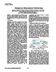
Reduction in end-to-end packet error rate (PER) may offset loss of resources due to frame segmentation. Multihop diversity, illustrated in Fig. 2, may have greater effect on reducing PER. This diversity takes advantage of inherent data redundancy in relaying and does not require additional radio resources such as transmit power and time slots. The packet error rate models discussed in Sections A-C. assume relaying nodes employ digital forwarding and that incorrectly detected signals are not relayed to subsequent nodes in the route; eliminating detection error propagation [4]. Relaying does not use ARQ for hops. Multihop, multihop selection combining, and multihop maximal ratio combining (MHMRC) models [2] are reproduced here for convenience. Section D. introduces a hybrid analog and digital MHMRC relaying model. A.
Multihop (MH) Generalizing the multihop scenario illustrated in Fig. 1, the packet error rate seen at the i’th node in a route, ri, can be expressed as, PER i = PER i −1 + (1 − PERi −1 )Pi −1, i
i ∈ {1, K , n} .
(3)
The PER at the source node, r0, is PER0=0 and the PER for the link between any nodes ri and rj is denoted by Pi,j. It should be noted that Pi , j = Pe (SNRi , j , mi , j ) . The PER for the destination node can be calculated by evaluating for i = n. B.
Multihop Selection Combining Diversity (MHSC) Using MHSC, nodes receive signals from previous nodes in the route and decode the multiple signals individually until the packet is detected correctly. The i’th node in a route, ri, will receive a maximum of i independent signals from the previous i nodes. The packet error rate can be expressed as
PERi = ∏ (PER j + (1 − PER j )Pj , i ) , i −1
j =0
i ∈ {1, K , n} .
m∈M
i ∈ {1, K , n} ,
Where, N m = { j | m j , j +1 = m, j = {0K i − 1}} ,
(5)
Nm = 0
1, (N m ) = PER j + (1 − PER j ) Pj ,i , (m) E ( Pe ),
E ( Pe( m ) ) =
∑
N ∈2 N m
Nm = 1 Nm > 1 (6)
∏ PER j ∏ (1 − PER j ) j ∈ N j∈N − N m
× Pe ∑ SNR (j ,mi ) , m j∈N Here M specifies the set of possible modes, m specifies the mode of the signals we are attempting to combine, Nm is the set of nodes transmitting with mode m, E ( Pe( m ) ) is the mean packet error rate of the signal received at node ri from the previous nodes transmitting with mode m, and SNR (j ,mi ) represents the SNR of the signal of mode m received at node ri from node rj. Nodes only relay correctly detected packets, therefore, the probability a relaying node relays a signal is weighted in the mean packet error rate expression. Here 2 N , the power set of Nm, contains all combinations of node transmission for nodes using mode m. N is the set of nodes that correctly detected the signal and relay to node ri. m
D. Hybrid Digital and Analog Relaying (HDAR) Permitting nodes to relay incorrectly detected signals as analog signals increases the number of signals to MRC combine at receivers. A relaying node will relay a digital signal when correctly detected, and it will relay an analog signal otherwise. We call this an HDAR system. The PER at node ri can be similarly expressed as (5) but (6) becomes, E ( Pe( m ) ) =
∑
N ∈2 N m
(7)
∏ PER j ∏ (1 − PER j ) j ∈ N j∈N − N m
× Pe ∑ SNR (j ,mi ) , m j∈N m
(4)
C. Multihop Maximal Ratio Combining Diversity (MHMRC) MHMRC combines signals received on previous hops with similar mode to reduce PER. Fig. 3 illustrates receiver operation for an example scenario. In the first stage of the receiver, signals transmitted on previous hops using similar modes are MRC combined reducing the PER of the resultant signal. In a secondary stage, signals from the MRC combiners are decoded individually. If hops do not use the same mode, MHMRC behaves as MHSC. For connections with nodes using MRC diversity, the packet error rate seen at any node, ri, is expressed as PER i = ∏ PER i( m ) ( N m ) ,
PER
(m) i
P G / η Where, SNR (j m,i ) = t j ,i SU
j∈N otherwise
U −1 P G a Gu ,u t j ,i ∏ u k =1 SU = U −2 U −2 η + ηa u G j , i 1 + ∑ ∏ a u G u k =1 k 0 Pt au = Pt G u , u + η k
k −1
U −1
i
i −1
∃s ∈ N
k
i
s = arg max(l < j ) l∈ N
U = {s} U {l | s < l ≤ j , l ∈ N m − N }
k
k
,uk +1
otherwise
The SNR can be calculated simply when node ri receives a correctly detected signal from node rj, j ∈ N (digital relaying). When calculating the SNR of a received analog signal, SU, we consider a chain of analog relaying nodes from node rs to node rj. The set of nodes transmitting with mode m is ordered by route, U = (u0, u1, ..., u|U|-2, u|U|-1). u0 = s, u|U|-1 = j and the remaining are intermediate analog relaying nodes. Node rj can not relay if there is no digital relaying node rs upstream in the route, SU = 0. au is the amplification factor at i
node ru and Gj,i is the link gain between nodes rj and ri. It is i
assumed all nodes transmit with power Pt and all hops have equal noise and interference power η. IV.
(1 − PER ) ,
(9)
i ∈ {1, K , n} .
n
1 ∑ D i =1 i −1, i n
To facilitate expression of routing, the metric is rewritten as
(1 − PER ) . 1 ∑D n
(10)
n −1 i=0
i
For n-hop connections, Rd = (r0, r1, ..., rn) and Md = (m0, m1, ..., mn-1). Rd is a n-hop route used to relay data to node d and is an ordered set consisting of n+1 relaying nodes where ri denotes the i’th relaying node in the route. The final node in the ordered set is the destination node d, rn = d. r0 denotes the source (the AP in the downlink). Md is an ordered set of modes used on hops, where mi denotes the mode of the i’th hop between nodes ri and ri+1. An n-hop connection contains n modes. Di is the AMC efficiency in bits/sym of the i’th hop between nodes ri and ri+1 using mode mi for that hop. PERn is the packet error rate seen at the destination node, rn. The PERn expression may be evaluated using equations (3), (4), (5) & (6), or (5) & (7) depending whether the diversity used at nodes is MH (no diversity), MHSC, MHMRC, or HDAR respectively. B.
for all h = 0 to M d( 0 ) − 1 and h ≠ h (max) for all m ∈ M d( 0 ) − m h( k ) M d( k +1) = M d( k ) mh( k +1) = m
if C ( Rd , M d( k +1) ) > C ( Rd , M d(max) ) M d(max) = M d( k +1)
Routing Metric The throughput expression may be used to form a routing metric [2]. The routing metric for a n-hop connection, Cn, to the destination node rn is,
C (R d , M d ) =
k =0 h (max) ≠ h do M d(max) = M d( k )
RELAYING NODE SELECTION ALGORITHM
A.
Cn =
AMM Algorithm:
Routing Algorithms Using the metric in (10), routing can maximize throughput for a multihop connection. We introduced a routing algorithm for MH, MHSC, and MHMRC systems capable of finding routes with throughput greater than or equal to singlehop and optimal 2-hop routes [2]. Once routes have been selected, connection throughput can be maximized by selecting hop modes to maximize MRC performance. Selecting similar modes allow more signals to be MRC combined and reduces PER. The adaptive modulation maximization (AMM) algorithm is given by,
h (max) = h end if end for end for M d( k +1) = M d(max)
k = k +1 while M d( k ) ≠ M d( k −1)
Where, h = hop index, h(max) = hop index of the mode change generating the maximum metric, M i( k ) = ordered set of modes used on hops in relay route to node i at iteration k, mh( k +1) = the h’th mode in the ordered set M d( k +1) = (m0 m1 ... m x −1 ) , C(R, M) = routing metric to the destination node in the ordered set R using the ordered set M of modes used on hops.
The algorithm examines the set of hop modes Md used in the connection to node d. For every iteration k, a mode for hop h, mh( k +1) , is changed. The mode change generating the maximum metric is used in M d( k +1) for the next iteration. When the set of hop modes do not change after iterating, the metric is maximized and further changes to hop modes will not increase throughput. Modulation selection can be also incorporated in routing. Here we define multihop adaptive modulation (MHAM) routing, a combination of the original MH routing algorithm [2] and AMM. The algorithm is described as, MHAM Algorithm:
k =0 N c( 0 ) = N
∀i , Ri( 0 ) = (cc, i ) , M i( 0 ) = (m cc(max) ) ,i
while N c( k ) > 0 N c( k +1) = {}
∀i , Ri( k +1) = R i( k ) , M i( k +1) = M i( k )
for all s ∈ N c( k ) for all d ∈ N − R s( k ) for all m ∈ M s( k ) U {m s(max) } ,d
if C ( Rs( k ) U {d }, M s( k ) U {m}) > C ( Rd( k +1) , M d( k +1) ) R d( k +1) = R s( k ) U {d }
M d( k +1) = M s( k ) U {m}
N c( k +1) = N c( k +1) U {d } end if end for end for end for k = k +1 end while
Where, N = set of all nodes, not including the central controller (AP), cc = element symbol denoting the central controller node, i, s, d = element symbol denoting a mobile node, N c( k ) = set of nodes which have a route change at iteration k, Ri( k ) = ordered set of relay nodes to node i at iteration k, mi(max) = hop mode between nodes i and j, selected by (1). ,j
We define Z=X U Y=(x0, x1, ..., xn-1, y0, y1, ..., ym-1) where X and Y are ordered sets containing n and m elements respectively, and the ordered set Z contains n+m elements. The algorithm can be viewed as a trellis containing the routes to nodes in the network, where the path through the trellis to a given node denotes the route in the network generating the maximum metric (throughput) for the particular node. The key difference between MHAM and the MH algorithm in [2] is the joint mode and route maximization. For every iteration, k, we examine possible routes from node s to } . By selecting a node d using hop modes m ∈ M s( k ) U {m s(max) ,d mode from the set of modes already used in the connection to node s, modes can be selected to increase the number of signals for MRC combining at node d. V.
SIMULATION MODEL
The simulation model assumes a propagation environment consistent with the ETSI-A channel model for office non-lineof-sight environments; a slow-fading Rayleigh channel model with a 50 ns RMS delay spread. Packet error rate, Pe(SNR, m), lookup tables for the ETSI-A channel are obtainable from previous studies [5], [6]. Shadow fading standard deviation is 5.1 dB and links are static for the duration of transmission. Received signals include white noise with power of -90 dBm. The propagation exponent is set to 3.4. Using a hexagonal cellular structure, we consider a scenario where constant interference originates from APs located at the center of the six nearest co-channel cells for the duration of transmission. Cluster size of 12 and hexagonal cell radius of 128 m and 256 m is used. The AP services 64 nodes randomly
and uniformly located throughout the cell. Nodes transmit with power of 23 dBm using omni-directional antennas. Nodes use adaptive modulation in the downlink. Table I defines mode settings and corresponding modulation efficiency, D, for various SNR ranges for the ETSI-A propagation environment [5]. SNR [dB] < 8.09 < 10.25 < 15.57 < 20.17 > 20.17
TABLE I – Adaptive modulation settings PHY-mode, m(max) D, [info. bits/ OFDM symbol] QPSK ½ 48 QPSK ¾ 72 16-QAM 9/16 108 16-QAM ¾ 144 64-QAM ¾ 216
Factors such as mobility and overhead due to relaying are omitted from the simulations. VI.
SIMULATION RESULTS
Fig. 4 and Fig. 5, depicting the CDF of network throughput for 128 m cells and 256 m cells respectively, indicate significant gains in throughput when using diversity and algorithms presented in Sec. IV. The probability of outage, the percentage of users who transmit with 0 Mbps, decreases from ~39% to ~0% and from ~83% to 0% for 128 m cells and 256 m cells respectively. Table II summarizes the results. Routing type indicates the model used to evaluate PER in the routing algorithm. Here SH = single hop and MH = multihop. MH refers to the routing algorithm presented in [2] and MHAM to the algorithm in this paper. SC, MRC, and HDAR refer to the corresponding packet error rate model. AMM, MHAM, and HDAR are only applicable to systems using MRC receivers. Routing Type SH MH MHSC MHMRC MHMRC-AMM MHAMMRC MHHDAR MHHDAR-AMM MHAMHDAR
TABLE II – Simulation results Avg. Throughput [Mbps] 128 m 256 m 7.75 2.07 12.77 4.17 13.17 4.70 13.19 4.70 13.29 4.89 13.27 4.85 13.98 5.20 14.20 5.44 14.32 5.62
Avg. Hops in Route 128 m 256 m 1 1 2.21 2.93 2.61 4.17 2.62 4.14 2.62 4.14 2.62 3.24 2.73 3.95 2.73 3.95 2.56 3.70
When relaying with diversity, throughput can almost be doubled compared to basic relaying. This diversity gain is essentially “free” since additional time slots and transmit power is not required. However, using relaying requires a greater number of hops and increases load on nodes as shown in Fig. 6 and Fig. 7 corresponding to 128 m and 256 m cells respectively. MHMRC performance shows little gain compared to MHSC. Since signals are relayed only when correctly detected, there is a lack of signals and MRC is not much more effective than SC. This trend is observed in MHMRCAMM and MHAMMRC. The lack of relayed signals due to incorrect detection is a severe bottleneck and performance does not increase significantly despite maximization of hop modes. Systems using HDAR benefit considerably from maximization of modes due to increased number of relayed signals and
diversity. Joint route selection and hop mode maximization (MHAM) discovers connections with greater throughput and fewer hops on average as compared to disjoint route selection and mode maximization (MH-AMM). VII.
DISCUSSIONS AND CONCLUSIONS
In this paper we investigated the effects of various multihop diversity relaying schemes and introduced novel algorithms able to discover routes in a network factoring diversity advantages using multihop SC and multihop MRC combining. Algorithms can also adapt hop modulations to further improve relaying performance when using MRC diversity. Our results show significant increase in network throughput and reduced outage probability without the need for extra time slots. However, MRC diversity only provides considerable gains when using mixed digital and analog relaying. Using a joint adaptive modulation and routing algorithm provides the most performance gain and reduces load on mobile nodes. Algorithms presented here may also be used in fixed relaying networks to mitigate the load on mobile nodes. More powerful diversity schemes such as code combining [7] can be used to increase relaying performance further.
Fig. 1 – Multihop relaying
Fig. 2 – Multihop relaying with diversity
ACKNOWLEDGEMENT
This research was funded by a grant from Communications and Information Technology Ontario (CITO). REFERENCES [1] H. Yanikomeroglu, “Fixed and mobile relaying technologies for cellular networks”, Second Workshop in Applications and Services in Wireless Networks (ASWN’02), pp. 75-81, July 2002, Paris, France. [2] S. Hares, H. Yanikomeroglu, and B. Hashem, "A relaying algorithm for multihop TDMA TDD networks using diversity", IEEE Vehicular Technology Conf., Fall 2003, Orlando, Florida, USA.
Fig. 3 – Example of a MHMRC diversity receiver for a 6 hop connection
1
[3] N. Esseling et. al., “Supporting cost efficient public 5GHz-WLAN roll out with a multihop HiperLAN/2 concept,” IEEE Vehicular Technology Conf.,, pp. 1180-1184, Spring 2002.
[5] J. Habetha, S. Mangold, and J. Weigert, “802.11a versus HiperLAN/2 – A comparison of decentralized and centralized MAC protocols for multihop ad hoc radio network,” Systemics Cybernetics and Informatics Conference, 2001. [6] J. Khun-Jush, P. Schramm, U. Wachsmann, and F. Wenger, “Structure and performance of the HiperLAN/2 physical layer,” IEEE Vehicular Technology Conf. , pp. 2667-2671, Fall 1999.
0.8
0.7 Pr(User Throughput