The boat carrying the sink can move in the water to help alleviate the unbalance power consumption of the sensor nodes and elongate the lifetime of the network ...
This full text paper was peer reviewed at the direction of IEEE Communications Society subject matter experts for publication in the IEEE ICC 2010 proceedings
DLING: A Distributed Mobile Sink Guiding Scheme for Sensor Networks 1
He Zhu1,2 , Dong Li1 and Li Cui1 Institute of Computing Technology, Chinese Academy of Sciences, Beijing 100190 2 Graduate University of the Chinese Academy of Sciences, Beijing 100049 {zhuhe, lidong, lcui}@ict.ac.cn
Abstract—The energy consumption rates of nodes vary in different positions in sensor networks, leading to the early depletion of the nodes and the disconnection of a network. In this paper, we present a distributed mobile sink guiding scheme (DLING) based on the center of gravity theory in physics. DLING regards the sensor network as an object composed of particles. Sensor nodes act as particles and their residual energy is treated as their ”weight”. We use the traditional discovering method for the center of gravity to compute the ”energy center” of a network. The nodes near the energy center have more residual energy and can afford more traffic load. Then we propose a novel scheme to guide the sink sojourning around the network’s center of energy so that the energy consumption of the nodes will be balanced. The simulation results demonstrate that DLING can achieve further improvements on the network lifetime in comparison with previous moving schemes while having low control costs. Index Terms—wireless sensor network, mobile sink, lifetime elongation, distributed algorithm
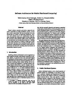
I. Introduction Energy is usually one of the most crucial resources in sensor networks because low-cost sensor nodes can neither carry large batteries nor get recharged in hostile environments. In a realistic sensor network, the energy consumption rates of nodes are usually different. The bottleneck nodes deplete their energy faster than others and soon create a choke point, which leads to blind areas and may even threaten the entire network. So network protocols should be carefully designed to balance the energy consumption among the sensor nodes. Since the hot spot is unavoidable [1] in a static sensor network, using mobile sinks is regarded feasible to achieve further improvements on the lifetime of sensor networks. This work is motivated by our ongoing wetland environmental monitoring project. We plan to deploy sensor nodes in various wetlands in Jinlin, Hubei and Qinghai Province in China to collect scientific data of these areas in order to prevent the wetlands from being polluted. Unlike the nodes in [2], generally floating on the ocean, nodes in our project work in the scenario shown in Fig. 1 are non-uniformly deployed in grasses, on trees, on the water or along the lakeside. The sink is a powerful device placed on a boat and can travel on water. Therefore, we guide the sink’s movement to alleviate the unbalance power consumption of sensor nodes and achieve longer lifetime of the network. Research efforts have been made regarding the issue of power balancing in sensor networks with the support of mobile sinks [3-11]. However, not all the approaches work properly in practical systems. The topology well-distributed in [3] is friendly to theoretical analysis while unusual in practice; the global topology information is required in [4], leading to heavy traffic burden and slow convergence time in large scale
Water Land Sensor node Source node Sink
Fig. 1. The scenario of the wetland monitoring application. Sensor Nodes are non-uniformly deployed in different conditions. The boat carrying the sink can move in the water to help alleviate the unbalance power consumption of the sensor nodes and elongate the lifetime of the network.
networks; the sink’s movement path is computed with off-line optimization algorithms in [5][6]. Such algorithms lack the feasibility in dynamic sensor networks. Instead, we present a distributed mobile sink guiding scheme (DLING) to guide the mobile sink in a non-uniform sensor network. DLING lets the nodes check energy usage within one-hop neighborhood to elect the guide node and send the guiding messages with the center of energy location to the sink. The relay node tries to merge all incoming guide packets from multiple peripheral guide nodes. It recalculates the center of energy and sends only one guide packet to the inner nodes till the sink. And the sink just checks the finally arriving guide packets and then works out the network’s location of energy center, which is the decision of its next stop. The major contributions of our work are summarized as the following aspects: • We propose a novel concept, that is, the energy center of the network, which makes an analogy to the center of gravity in Newtonian mechanics. • We develop a new distributed sink guiding algorithm (DLING) using the energy center concept. The algorithm guides the sink to the district where the network will have the longest prospective lifetime. • We implement DLING on the NS-2 simulator and the results show that our strategy can significantly prolong the network lifetime and reduce the difference of power consumption between the nodes. The rest of the paper is organized as follows. In the next
978-1-4244-6404-3/10/$26.00 ©2010 IEEE
This full text paper was peer reviewed at the direction of IEEE Communications Society subject matter experts for publication in the IEEE ICC 2010 proceedings
section we discuss the related work. Section III gives the system model and then formulates the problem. Section IV shows the design and implementation of the distributed sink guiding algorithm. Simulation results are given in Section V. Section VI concludes the paper. II. Related Work Much work about sink mobility has been done in recent years. We classify it into two general categories: theoretical analysis and joint mobility routing design. Theoretical analysis on mobile sinks can be found in [3][5][7][8]. This kind of methods usually propose and solve a mathematical programming model for the problem. For example, Z.M. Wang et al. present a linear programming scheme in [3] to find the optimal sojourn time for the sink to move in a homogeneous network. They make the overall network lifetime about five times more than that with a static sink. The authors of [7] poses an integer programming to determine the new location for the mobile sink which moves at the beginning of every round. The centralized analysis often needs the global topology information and has a high computational complexity. The analysis in [3] also lets the network be homogeneous, which may not be feasible in a heterogeneous network. The authors of [9][4][10][11] all refer to the designs of joint mobility routing. R.C. Shah et al. present Data MULEs in [10]. MULEs pick up data from the sensors when in close range, buffer it, and drop off the data to wired access points which would cause significant delay. Two moving schemes are proposed in [4]. Each data packet contains the highest and lowest residual energy among the nodes on its delivery path. In the one-step moving scheme, the sink moves to the node with the highest residual energy periodically. In the multi-step moving scheme, the sink moves to the node with the highest energy among its two-hop neighbors step by step. This kind of method would cause considerable control costs using the first scheme and may be far from the optimum movement using the second one. III. System Model And Problem Formulation In our system model, the sensor network is defined as a connected undirected graph G = (V, E), where V represents the set of all nodes and E represents the set of undirected links (u, v), such that u, v ∈ V. The routing cost of link (u, v) is c(u, v), and c(u, v) = −1 when (u, v) � E. The sink decides the new destination and moves at a regular interval T s . We call it a round. We take the energy-efficient single-path algorithm as our routing scheme. We define the network lifetime L from the beginning to the disconnection of the network, reflected by the overall rounds of the sink C s and the length of a round T s : L = (C s − 1)T s
(1)
Our goal is to maximize the total movement count C s of the sink, and finally maximize the network lifetime L. Due to the high complexity of the problem above which we could anticipate, we give an approximation algorithm instead. Like the center of gravity of objects with irregular shapes, we treat the remaining energy of nodes as their ”weights”. The center of energy of the whole network will then be calculated according to this analogy. Different loads cause nodes lose
their ”weights” in various speed so that the center of energy moves. Our algorithm keeps the sink following the moving ”center of gravity”, which really helps balance the energy distribution of the network. A. Center of Energy Let xi and yi be the coordinates of node i’s position pi . The center of energy Re in a heterogeneous sensor network is defined as the average of nodes’ position pi weighted by their remaining energy ri . � � � ri pi ri xi ri yi ⇔ xb = � , yb = � (2) Re = � ri ri ri Like the center of gravity, the general energy distribution of the network can be reflected by Re . When the sink causes hotness around its periphery, Re moves away from this ”emergent” area and get closer to the area where nodes have more residual energy. Tracing Re would help the sink avoid the poorenergy area and give opportunities to every node to work more efficiently. If aware of global energy distribution, the sink could easily locate Re according to equation (2). The centralized algorithm is illustrated in Algorithm 1 below. Algorithm 1 Centralized Algorithm for Center of Energy 1: CENTER-OF-ENERGY() 2: initialize variables rx sum , ry sum , r sum 3: for each node vi do 4: rx sum = rx sum + ri ∗ xi 5: ry sum = ry sum + ri ∗ yi 6: r sum = r sum + ri 7: end for 8: return (rx sum /r sum , rx sum /r sum ) The algorithm simply checks the residual energy of all nodes and calculates x and y coordinates of Re . The sink can locate the new destination with the complexity of O(|V|). However, due to the large communication costs for getting the global energy information, the centralized way above actually costs much more extra energy than it can save. Re1
Re1 Re
Re2
Re
Re
Re13
Re2 Re3
Re3
Fig. 2. The center of energy conforms the law of association. Re can be either directly calculated by energy information of the six nodes in the figure or recurrently calculated as Re1 , Re2 , Re1 and Re13 , then merged into Re .
B. Distributed way for Center of Energy Calculation Like the operation of addition, the center of energy calculation conforms to the law of commutation and association according to the proof below: j−1 k k n n � � � � � ri xi ri xi + ri xb jk + ri xi ri xi i= j i= j i=1 i=k+1 i=1 xb jk = ⇒ xb = = , n n k � � � r r i i ri i= j
i=i
i=i
This full text paper was peer reviewed at the direction of IEEE Communications Society subject matter experts for publication in the IEEE ICC 2010 proceedings
N2 v rv 2 74.6 ... ... 5 72.3 ... ...
N2 v rv Max 2 74.6 ... ... 5 72.3 ... ...
V1
Cs 27 ... 27 ...
r5
V4 r5
V5 r5
V2
Cs 27 ... 27 ...
V2
r5
V7
V1
V4
(a) Each sensor node, v5 for example, broadcasts its remaining energy information to its one-hop neighbors at the beginning of a round.
(b) Node v2 is elected as the guide node. It calculates the energy center’s position of its neighbors and itself, and sends it to the next hop. Fig. 3.
yb jk =
j−1 �
ri yi
i= j k � i= j
⇒ yb = ri
i=1
V6
V8
Nsink rv 74.1 74.6 73.1 ...
V7
V14 Cs 26 27 27 ...
V8
V17
V3
V3
k �
V9
V5 Guide packet to the sink
v 14 8 7 ...
ri yi +
k � i= j
i=i
(d) The sink locates Re of the network based on the highly merged energy center information from its neighbors. Then it moves to Re .
A process of the distributed mobile sink guiding scheme (DLING).
ri yb jk + n �
(c) Node v9 receives guide packets from both v6 and v8 . It recalculates and then sends out the energy center according to the law of association.
ri
n � i=k+1
n �
ri yi =
ri yi
i=1 n �
ri
i=i
Fig. 2 shows the interesting law above through an example. Thanks to the center of energy’s features, we propose a distributed sink guiding algorithm (DLING) to help the sink approximate the network’s center of energy with lower communication costs, especially for those high-load nodes near the sink. IV. Distributed Mobile Sink Guiding Scheme A. Overview DLING will be executed every time when the sink steps into a new movement round. At that moment, nodes get energy information of their neighbors with a restricted flooding method. Then a part of nodes, also called the ”guide nodes”, calculate the center of energy values among their neighbors and send the results to the sink. The energy information generated by multiple guide nodes will be merged by the relay nodes. At the sink side, it only receives a few highly merged energy packets and calculates the new destination by them. The process will be repeated round by round till the disconnection of the network. B. DLING: Guide Message Generation and Mergence A DLING process can be divided into four stages in general, as illustrated in Fig. 3. We take node v2 for example. It maintains its neighbor list array N2 storing the remaining energy information and the round counts of its neighbors. Suppose the round number has increased from 26 to 27, v2 broadcasts its latest energy information and receives packets of the same kind from all its one-hop neighbors (v5 for instance). Meanwhile its neighbor list is updated. We can see this process in Fig. 3(a), where v5 ’s remaining energy has been changed to 72.3. In Fig. 3(b), v2 finds that it has the highest energy among its neighbors. Therefore, it generates a guide packet with Re of its neighbors and sends it to the sink. The node which receives guide packets from its downstream nodes would not forward them immediately. It will wait for a carefully designated time span trelay , in which all incoming guide packets have the time to be received and merged. Then the node forwards one new packet in place of all guide packets it has received as Fig. 3(c) shows. Nodes with lower hop counts receive less guide packets with the merging method, and consequently cost less
Algorithm 2 The DLING Process 1: DLING() 2: send out energy packet < rv , C s , BROADCAST> 3: start the timekeeper t 4: set the neighbor list update expiration time tupdate 5: while t ≤ tupdate do 6: listen and wait for energy packets from neighbors 7: if receive energy packet then 8: update the record of v with < rv , C s , DESTINATION> 9: end if 10: end while 11: if my rv is the highest among Nv then 12: mark myself as the guide node 13: else 14: mark v having the highest rv as my guide node 15: end if 16: while t ≤ trelay do 17: listen and wait for guide packets to the sink 18: if receive guide packet then 19: if I am the guide node then 20: recalculate Re with the guide packet 21: else if from my guide node then 22: forward the guide packet to next hop 23: else 24: forward the guide packet to my guide node 25: end if 26: end if 27: end while 28: send guide packet < Re , C s > to the next hop 29: return SUCCESS
energy. Fig. 3(d) reveals this process. The detailed algorithm of DLING scheme is also illustrated in Algorithm 2. We discuss the worst case of the communication costs when DLING works. First we suppose the number of one-hop neighbors for each node is Nmax at most. The max hops from a node to the sink are Hmax . At the stage of broadcasting DLING packets, every node sends one and receives Nmax broadcasts. So the network will process |V| (Nmax + 1) packets in all at this stage. When the network steps into the guide packet sending |V| stage, only Nmax +1 nodes send guide packets. Assume these packets all arrive at the sink within Hmax hops. This stage max will cause 2|V|H Nmax +1 more packets to be received and forwarded. Therefore, the total number of packets in a single round is
This full text paper was peer reviewed at the direction of IEEE Communications Society subject matter experts for publication in the IEEE ICC 2010 proceedings
9.4
x 10
Variance of Residual Energy of Nodes
8
8
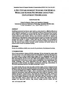
We can see the variance of MRE is 35.3% higher than that of RANDOM and 50.9% higher than that of DLING. The network with the STATIC scheme disconnects earliest because nodes near the sink are given persistent heavy loads, causing them to die at the simulation time of about 5.5 × 10⁴ s.
DLING RANDOM MRE STATIC
6
B. Control Costs Evaluation 4
2
0 0
1
2
3
4 5 6 Network Lifetime (s)
7
8
9
10 4
x 10
Fig. 4. The variances of the remaining energy of nodes with different schemes. DLING has the lowest variance of the remaining energy among the four schemes, which implies a better balance of energy consumption.
We evaluate the control costs of DLING in various network scales, from 20 to 100, and the simulations are repeated for five times in the random topology. The result shown in Fig. 5 indicates that the average control costs of DLING are much less than the costs of MRE scheme in every network scale. The rate of growth of the control costs is smaller when the network becomes larger because DLING merges most guiding packets according to the center of energy theory. Although the increasing speed of MRE scheme slows down when the network scale is reaching 100, its control costs are still 79.2% higher than that of DLING.
+ |V| (Nmax + 1). Thus the communication complexity of DLING is O(|V|).
10
V. Simulation Results and Analysis
8
2|V|Hmax Nmax +1
A. Residual Energy Variance of Nodes We deploy 100 nodes and repeat the simulations five times for each scheme in random topologies. We record each node’s residual energy every 5000 seconds and calculate their variances. The result in Fig. 4 shows that DLING has the lowest variance of remaining energy among the four schemes. The sink using the RANDOM scheme balances the sojourn time in the network but ignores different load of nodes in different time, so it shows a greater variance than DLING. The MRE scheme makes the best decision to move. However, it has pretty high control costs which spends much more energy than the decision saves. When the simulation time is 9.5 × 10⁴ s,
MRE
9
DLING
Control Packets Count
In this section, we provide simulation results to study the performance of the DLING scheme. We compare the DLING scheme with three other ones, that is, the traditional scheme with a static sink (STATIC), the scheme with one sink moving randomly each round (RANDOM) and the scheme with the sink moving to the node with the maximum residual energy (MRE). We are interested in four metrics: (1) The energy distribution of the network, reflected by the variance of each node’s residual energy when the network disconnects; (2) The network lifetime with the four different schemes; (3) Control costs of DLING and MRE schemes which generate control packets; (4) Relevance between the DLING round length and the network lifetime. We perform the simulation with the NS-2 simulator. We use the two-ray-ground radio propagation model and a CSMA protocol in the MAC layer. We deploy multiple nodes from 5 to 100 in a 2000m × 2000m field, randomly scattered. Each node has a communication range of 250m and an initial energy of 1.0 × 10⁵ µJ. The lengths of a data packet and a control packet are set to 29 bytes and 16 bytes respectively. We ignore the time spent by the sink on its way to a new destination. The power consumption model in [12] is used for the simulation.
4
x 10
7 6 5 4 3 2 1 0
20
40
60 Network Scale
80
100
Fig. 5. The average control costs with varying network scales in random topologies. DLING costs much less than MRE in various network scales and performs even better when the network scale becomes larger, because it merges guiding packets and thus saves more control costs.
C. Network Lifetime Comparison We use the same simulation configuration, take the average lifetime of the five repeats and then compare the snapshot of DLING with three other schemes when the network has been disconnected. We have noticed in Fig. 6 that as an approximation algorithm, DLING still cannot completely prevent nodes in the center of the network from dying first. However, compared with other three schemes, the network lifetime with DLING is significantly longer. The network with the STATIC scheme suffers from the funneling effect and disconnects earliest of the four when most of the nodes just cost a little energy. The RANDOM scheme makes an improvement, but the destination it sojourns may be an energy hole, which is helpless to extend the lifetime. The figure demonstrates that the network lifetime of DLING is about 79.0% longer than that of RANDOM. The MRE scheme’s high control costs make its lifetime 29.6% shorter than that of DLING.
This full text paper was peer reviewed at the direction of IEEE Communications Society subject matter experts for publication in the IEEE ICC 2010 proceedings
DLING
DLING
DLING 100 000
100 000
50 000
50 000
Lifetime �s�
0
0
0
0
0
0
200 500
y �m�
600
1000
50 000
Lifetime �s�
200 400
100 000
STATIC
y �m�
(a) DLING vs. STATIC.
0
0
0
200 500
400
x �m�
Lifetime �s�
600
1000
x �m�
(b) DLING vs. RANDOM
RANDOM
500
400 y �m�
600
1000
MRE
x �m�
(c) DLING vs. MRE
Fig. 6. The lifetime distribution of the nodes with different schemes when the network disconnects. STATIC causes the lowest network lifetime, in which few nodes have depleted the energy when the network disconnects. RANDOM acts better than the STATIC one, but the network lifetime with DLING is still 79.0% longer than that with RANDOM. MRE’s high control costs make the lifetime 29.6% shorter than that with DLING.
5
1.4
x 10
the three other schemes. Intensive simulations indicate that DLING is insensitive to changes of the sink movement round length. Future work of the authors will include implementing DLING on the sensor network prototype for the environmental monitoring in wetlands and revising the design to address the issues arise in practice.
DLING
Network Lifetime (s)
1.2
1
0.8
0.6 0
20
40
60 80 100 120 140 The Length of Sink Movement Round
160
180
200
Fig. 7. Network Lifetime with varying lengths of sink movement round. DLING is light-weight because the network lifetime does not change a lot before the length of sink movement round exceeds 160.
D. Impact of the Length of Sink Movement Round We run a group of simulations of the network with 100 nodes in random topologies. The length of the sink movement round increases from 20 to 200 times of the fixed data gathering period. The results in Fig. 7 show that network lifetime does not change a lot. Usually, short movement round leads to high control costs and causes the early disconnection of the network. But when the movement round is too long to balance the power consumption, the sink acts like a static one more. Therefore, the lifetime of the network may fall down fast, too. We can see such phenomenon in Fig. 7 after the length of sink movement round exceeds 160. DLING achieves its best performance when the round length is around 140 which balances the control costs and mobility benefits. The communication complexity of DLING is O(|V|), making it insensitive to the changes of the sink movement round length. So DLING is light-weight. VI. Conclusions and Future Work We propose a distributed mobile sink guiding scheme (DLING) based on the center of gravity theory. We present the ”center of energy” concept to point out the general energy usage of a network. We design a distributed sink guiding algorithm based on DLING and implement it on NS-2. The results demonstrate a longer network lifetime compared to
Acknowledgment We thank the invaluable comments from the reviewers and the contributions from Changcheng Huang, Haiming Chen and Yiwen Wang. This work is co-sponsored by the National Basic Research Program of China (973 Program) under grant No.2006CB303000, the National High Technology Research and Development Program of China (863 Program) under grant No.2007AA01Z2A9 and the National S&T Major Project under grant No.2009ZX03006-001. References [1] S. Olariu and I. Stojmenovic. Design guidelines for maximizing lifetime and avoiding energy holes in sensor networks with uniform distribution and uniform reporting. In Proc. of IEEE INFOCOM ’06, Barcelona, Catalunya, SPAIN, 2006. [2] Kebin Liu, Mo Li, Yunhao Liu, Minglu Li, Zhongwen Guo, and Feng Hong. Passive diagnosis for wireless sensor networks. In Proceedings of the 6th ACM conference on Embedded network sensor systems, pages 113–126, Raleigh, NC, USA, 2008. ACM. [3] Z.M. Wang, S. Basagni, E. Melachrinoudis, and C. Petrioli. Exploiting sink mobility for maximizing sensor networks lifetime. In Proc. of IEEE HICSS ’05, Big Island, Hawaii, USA, 2005. [4] Y. Bi, J. Niu, L. Sun, H. Wei, and Y. Sun. Moving schemes for mobile sinks in wireless sensor networks. In Proc. of IEEE IPCCC ’07, New Orleans, Louisiana, USA, 2007. [5] Y. Gu, D. Bozdag, E. Ekici, F. Ozguner, and C. Lee. Partitioning based mobile element scheduling in wireless sensor networks. In Proc. of IEEE SECON ’05, Santa Clara, California, USA, 2005. [6] A. Chakrabarti, A. Sabharwal, and B. Aazhang. Power optimization in sensor networks with a path-constrained mobile observer. ACM Transactions on Sensor Networks, 2005. [7] S.R. Gandham, M. Dawande, R. Prakash, and S. Venkatesan. Energy efficient schemes for wireless sensor networks with multiple mobile base stations. In Proc. of IEEE GLOBECOM ’03, San Francisco, USA, 2003. [8] W. Wang, V. Srinivasan, and K. Chua. Using mobile relays to prolong the lifetime of wireless sensor networks. In Proc. of ACM MOBICOM ’05, Cologne, Germany, 2005. [9] J. Luo and J.-P. Hubaux. Joint mobility and routing for lifetime elongation in wireless sensor networks. In Proc. of IEEE INFOCOM ’05, Miami, FL, USA, 2005. [10] R.C. Shah, S. Roy, S. Jain, and W. Brunette. Data MULEs: modeling a three-tier architecture for sparse sensor networks. In Proc. of IEEE SNPA ’03, Anchorage, Alaska, USA, 2003. [11] Y. Wu, L. Zhang, Y. Wu, and Z. Niu. Interest dissemination with directional antennas for wireless sensor networks with mobile sinks. In Proc. of ACM SenSys ’06, Boulder, Colorado, USA, 2006. [12] V. Shnayder, M. Hempstead, B. Chen, G.W. Allen, and M. Welsh. Simulating the power consumption of large-scale sensor network applications. In Proc. of ACM SenSys ’04, Baltimore, MD, USA, 2004.