Conference on Turbulence and Interactions TI2006, May 29 - June 2, 2006, Porquerolles, France. DNS of a Turbulent Channel Flow with Streamwise Rotation at.
Conference on Turbulence and Interactions TI2006, May 29 - June 2, 2006, Porquerolles, France
DNS of a Turbulent Channel Flow with Streamwise Rotation at Different Reynolds Numbers T. Weller∗ , M. Oberlack∗ ∗ Fluid
Dynamics Group, Technische Universit¨at Darmstadt, Petersenstraße 13, D-64287 Darmstadt, Germany ABSTRACT
In this work a turbulent channel flow rotating about the streamwise direction is presented. The theory is based on the investigations of [3] employing the symmetry group theory. It was found that a cross flow in the spanwise direction is induced. Statistical evaluations have shown that all six components of the Reynolds stress tensor are non-zero. A series of direct numerical simulations (DNS) has been conducted at rotation number Ro=20 for different Reynolds numbers. In this paper the results of the DNS are presented and discussed.
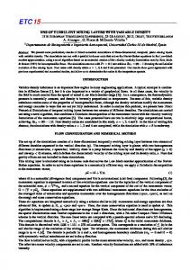
I NTRODUCTION Rotating turbulent flows play more a major role in engineering applications such as in gas turbine blade passages, pumps and rotating heat exchangers to name only a few. In these cases secondary flows are induced caused by centrifugal or Coriolis forces. Investigations of [3] using symmetry theory showed that there is a new turbulent scaling law related to the turbulent channel flow rotating about the mean flow direction. Figure 1 depicts the flow geometry. x2
can be deduced by investigating the mean momentum equation and the Reynolds stress transport equation. Statistical evaluations have shown that all six components of the Reynolds stress tensor are non-zero. Both the predicted cross flow and the non-zero components of the Reynolds stress tensor could be verified in a DNS at Reynolds number Re=180 for different rotation rates [5]. In this paper the results of a DNS at rotation rate Ro=20 at three different Reynolds numbers (Re=180, 270 and 560) are presented and discussed. The main objective of the present paper is to analyze these effects at different Reynolds numbers.
x1 u3
Ω1
D IRECT N UMERICAL S IMULATION
u1 x3
Numerical Method and Computations
The numerical technique which was chosen is a Fig. 1. Sketch of the flow geometry of a turbulent standard spectral method with Fourier decompochannel flow rotating about the mean flow direction sition in streamwise and spanwise direction as well as Chebyshev decomposition in wall-normal The flow has several common features with the direction. The numerical code for channel flow classical rotating channel flow rotating about the was developed at KTH/Stockholm [2]. Addispanwise direction [1] but also has some different tional features such as the streamwise rotation characteristics. The induction of a mean velocity and statistics were added during the project. All in x3 -direction [4] is the most obvious difference flow quantities are non-dimensionalized by h/2 compared to the classical case. This cross flow and ucl where h is the channel width and ucl
is the center line velocity of the flow field. The boundary conditions are non-slip at x2 = ±1 and periodic in x1 - and x3 -direction. For all computations the pressure-gradient is kept constant. Further details on the numerical scheme may be obtained from [2]. After the simulations were finalized all flow quantities were normalized on the friction velocity uτ . Hence the Reynolds number is defined by huτ Reτ = 2ν
25 20
u¯+ 1
15 10 Re = 180 Ro = 270 Ro = 560
5 0 -1
(1)
-0.5
0
0.5
1
x2 Fig. 2. Streamwise mean velocity profiles at Ro=20 and different Reynolds numbers.
and the rotation number as Ωh Ro = . uτ
The normal and shear stresses clearly increase with increasing Reynolds number.
2
(2) 1
u¯+ Three computations at rotation number Ro=20 3 0 for Reynolds numbers Re = 180, Re = 270 -1 and Re = 560 have been conducted. The size of Re = 180 Re = 270 the domain used in the x1 , x2 , and x3 directions Re = 560 -2 are respectively 8π, 2 and 4π for all computa-1 0 1 -0.5 0.5 x2 tions. The used grid resolution at Reynolds number Re = 180 is 256 × 129 × 128, at Re = 270 Fig. 3. Streamwise mean velocity profiles at Ro=20 256 × 193 × 256 and at Re = 560 512 × 257 × and different Reynolds numbers. 12 256. All computations were run for 10000 h/2 ucl Re = 180 Re = 560 10 time units and the statistics accumulation was performed for the last 5000 time units. 8 Main Profiles and Reynolds Stress Tensor
In figures 2 and 3 the mean velocity profiles for three different Reynolds numbers are visualized. The predicted cross flow could also be verified in the DNS. Both the streamwise and spanwise profiles increase with increasing Reynolds number. From Reynolds number Re=180 to Re=270 rather weakly but for Re=560 the increase is clearly visible. From the variety of statistical one-point quantities, the Reynolds stress tensor is shown in figures 4 and 5 at rotation number Ro=20 for two Reynolds numbers Re=180 and Re=560. The stresses for Re=270 (not shown here) are very similar to these of Re=180. As predicted from the lie group analysis [3] the DNS shows also that all six components of the Reynolds stress tensor are non-zero and all statistical curves are symmetric or skew-symmetric about the centerline.
u0i u0i
+ 6
u1u1 u2u2 u3u3
4 2 0 -1
0
-0.5
0.5
1
x2
Fig. 4. Reynolds normal stresses u0i u0i . 3 Re = 180
Re = 560
2
u0i u0j
+ 1
u1u2 u1u3 u2u3
0
-1
-0.5
0
x2
0.5
Fig. 5. Reynolds shear stresses u0i u0j .
1
Isosurface of the wall-normal velocity field
Fig. 6. Isosurface of the wall-normal velocity field at Ro=20 and Re=180.
Fig. 7. Isosurface of the wall-normal velocity field at Ro=20 and Re=270.
Fig. 8. Isosurface of the wall-normal velocity field at Ro=20 and Re=560.
In figures 6 - 8 isosurfaces of the wall-normal velocity field are visualized at an instantaneous time unit t = 10000 h/2 for different Reynolds uc l numbers. Apparently with increasing Reynolds number the formed turbulent structures become longer and thinner.
C ONCLUSIONS
With the DNS the induced phenomena of a cross flow in spanwise direction has been computed for different Reynolds numbers. It is to mention that the mean velocity in both streamwise and spanwise direction increases for a representative rotation number Ro=20 at different Reynolds numxz-slices of the streamwise vorticity field bers. Furthermore, it is shown that all components of the Reynolds stress tensor are non-zero and The figures 9 and 10 show the xz-slices for y=0.9 that all statistical curves are symmetric or skew(near the wall) of the streamwise vorticity field symmetric about the centerline. In the isosurfaces at an instantaneous time unit t = 10000 h/2 for of the velocity field it is shown that elongated turucl two different Reynolds numbers. Because of the bulent structures are formed. For higher Reynolds limited space only the first half of the channel is numbers the structures are much longer and thinshown. The plot at Re=270 looks very similar to ner. In the vorticity field the structures are dithis at Re=180, therefore it is not shown here. For verted from the streamwise direction because of increasing Reynolds numbers the number of vor- the rotation. This effect should be also analyzed tices increases, but the structures become smaller. for different rotation rates. Future research is unIt is important to mention that caused by the ro- der current investigation. tation the structures are diverted from the streamwise direction. BIBLIOGRAPHY [1] Johnston P.J., Halleen R.M. and Lazius D.K. ”Effects of spanwise rotation on the structure of two-dimensional fully developed turbulent channel flow”, J. Fluid Mech., Vol. 56, pp.533–557, 1972. [2] Lundbladh A., Henningson D. and Johanson A. ”An efficient spectral integration method for the solution of the Navier-Stokes equations”, FFATN 1992-28, Aeronautical Research Institute of Sweden, Bromma, 1992. Fig. 9. xz-slice (y=0.9, near the wall) of the streamwise vorticity field at Ro=20 and Re=180.
[3] Oberlack M., Cabot W. and Rogers M.M. ”Group analysis, DNS and modeling of a turbulent channel flow with streamwise rotation”, Studying Turbulence Using Numerical Datebase VII, Center for Turbulence Research, Stanford University/NASA Ames, pp. 221–242, 1998. [4] M. Oberlack ”A unified approach for symmetries in plane parallel turbulent shear flows”, J. Fluid Mech., Vol. 427, pp.299–328, 2001. [5] Weller T. and Oberlack M.”DNS of a Turbulent Channel Flow with Streamwise Rotation Investigation on the Cross Flow Phenomena”, accepted for publication in Proc. of DLES6, 2005.
Fig. 10. xz-slice (y=0.9, near the wall) of the streamwise vorticity field at Ro=20 and Re=560.