doepfer. System A - 100. ADSR A-140. 1. 1. Introduction. Module A-140 (ADSR)
is an envelope generator, and, since it puts out control voltages, counts as one.
System A - 100
doepfer
ADSR A-140
1. Introduction Gate
A-140 ADSR
Retrigger
Attack
Output
Decay
Output
Inverse Output ADSR Control
Sustain
Release
Time Range
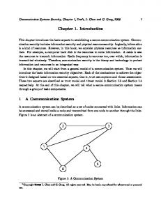
Module A-140 (ADSR) is an envelope generator, and, since it puts out control voltages, counts as one of the modulation devices in a modular system. As soon as the gate input receives sufficient voltage, the ADSR generates a variable voltage, changing in time, called an envelope. This varying voltage is output in normal (positive) and inverted form, and can be used, eg., for voltage controlled modulation of a VCO, VCF, or VCA, or for processing other modules’ inputs and outputs. The shape of the envelope is governed by four parameters: Attack, Decay, Sustain and Release (see Fig. 1 on page 3). The envelope is started (triggered) by a gate signal either from the INT.GATE voltage on the system bus, or, if a signal is put into it, from the gate input socket. The envelope can also be re-triggered, ie. start from scratch again, each time a trigger signal is sensed at the Retrig. input socket, when the gate is still open (see Fig. 2 on page 5).
1
A-140 ADSR
System A - 100 Controls:
2. ADSR overview
1 A:
Attack time control
ADSR
2 D:
Decay time control
ENVELOPE GEN.
3 S:
Sustain level control
4 R:
Release time control
A-140 Gate
➊
A 0
➀
10
➋
D 0
➁
10
In / Outputs:
Output
➌
S 0
➂
10
Output
➍
R 0
Inverse Output H
L
M
➃
! Gate:
Input for gate voltage
" Retrig.:
Input for re-trigger voltage
§ Output:
Output: responds to a gate signal by putting out the voltage envelope set by the controls.
$ Output:
ditto
10
ADSR Control
➄
Time Range
➅ 2
5 ADSR Control:LED envelope state indicator 6 Time Range:Three-position range switch
Retrig.
➎
doepfer
% Inverse Output: responds to a gate signal by putting out an inversion of the voltage envelope set by the controls.
System A - 100
doepfer
1 A
3. Controls The ADSR puts out a varying voltage, called an envelope, whenever a gate signal is sensed (see Fig. 1). Attack Time
ADSR A-140
Release Time
Decay Time
approx. +8 V
With this control you set the envelope’s attack time. Whenever the envelope is triggered - via the internal gate, a ‘note on’ command via a MIDI/CV interface, or a gate signal at gate input 1 - a control voltage is output at sockets 3 and 4, rising to maximum in the time set by this control.
2 D This control sets the decay time: the time it takes for the control voltage output to fall to the level set by S, the sustain control.
Sustain Level
3 S Time ➨ +3 ... +12 V On
Off
Fig. 1: An ADSR envelope and its parameters
0V
This control sets the sustain level of the envelope the steady-state voltage level after the decay phase. This level remains the same until the gate is closed.
4 R This control sets the release time of the envelope. As soon as the gate signal finishes, for instance when the key that triggered the envelope is released, or a note off command is received via a MIDI/CV interface, the control voltage falls to zero, at a rate set by this control. 3
A-140 ADSR
System A - 100
5 ADSR Control
4. In / Outputs
LED 5 gives a visual indication of the envelope voltage at the output.
! Gate
doepfer
Socket ! is the ADSR’s gate input.
6 Time Range
H The gate input is a switched socket, normalled
This 3-position rotary switch lets you select the right time range for your requirements. The three positions are: • H (high):
up to minutes
• M (medium):
standard mid-range
• L (low):
down to less than 100 µsec
to the INT. GATE circuit on the system bus. A gate signal on this circuit (for instance from a keyboard) will trigger the ADSR, even without an input to socket !. If on the other hand you connect a gate signal to socket !, then the connection with the system bus is broken, and the ADSR is triggered from this socket instead. If you want, you can undo the normalling to the system bus more permanently, by turning the A-100 off, removing the A-140 module, and taking out the little red jumper in the top right-hand corner of the circuit board.
4
System A - 100
doepfer
ADSR A-140
" Retrig.
% Inverse Output
Socket " is the ADSR’s retrigger input, which can be connected, for instance, to the output from an LFO. That means that while the gate is open, the envelope re-triggers every time it senses a pulse from the LFO (see Fig. 2).
The Inverse Output carries exactly the same voltage envelope as the ordinary outputs but inverted - with negative instead of positive voltages (see Fig. 3).
ADSR
Gate
Output 8V
0V
Inverse Output
A
D
S
R
0V
A
D
S
R
Retrig. -8V
Fig. 2: Envelope re-trigger system
§ Output
•
Fig. 3: normal and inverted envelopes
$ Output
Whenever the ADSR is triggered, these outputs carry the envelope voltage as defined by the Attack, Decay, Sustain and Release parameters (see Fig. 3).
5
A-140 ADSR
System A - 100
5. User examples The envelope generated by the ADSR can be used for most kinds of modulation: • ADSR - VCA Modulation of loudness / amplification over time. • ADSR - VCA for voltage control of any in / output processes, with the process time controlled by the A, D, S, and R parameters. • ADSR - VCF Modulation of the cut-off frequency produces a constantly evolving sound spectrum. • ADSR - VCO (PWM) Modulation of the pulse width of a VCO produces a constantly changing timbre. • ADSR - VCO (FM) Modulation of the pitch control voltage produces variation in pitch as a note progresses (and at very short envelope settings produces variation of timbre). • ADSR - VCP Modulation of the phase shift of an A-125 VCP produces variation in phase shift as a note progresses. For this function slow settings of A, D and R parameters should be used.
6
doepfer
• ADSR - VCLFO Control of the frequency of an A-147 VCLFO produces variation in LFO frequency as a note progresses. For this function slow settings of A, D and R parameters should be used. Examples and further notes can be found in the manuals for the individual modules.
doepfer
System A - 100
ADSR A-140
6. Patch-Sheet The following diagrams of the module can help you recall your own Patches. They’re designed so that a complete 19” rack of modules will fit onto an A4 sheet of paper. Photocopy this page, and cut out the pictures of this and your other modules. You can then stick them onto another piece of paper, and create a diagram of your own system.
A-140
ADSR
Gate
A-140
ADSR
Gate A
10
0
Retrig.
Retrig.
0
• Draw in patchleads with colored pens. • Draw or write control settings in the little white circles.
H
L
M
Time Range
ADSR Control
10
0
10
S
10
Output
Inverse Output
P
0
10
0
Output
Output
R 0
10
S
10
Output
0
D
10
Output
0
10
Retrig.
S
Make multiple copies of your composite diagram, and use them for remembering good patches and set-ups.
0
D
10
Output
A
10
D 0
ADSR
Gate
A 0
A-140
R 0
Inverse Output H
L
M
Time Range
10
ADSR Control
R Inverse Output H
L
M
ADSR Control
Time Range
7
A-140 ADSR
8
System A - 100
doepfer