Does DOF Separation on Elastic Devices Improve User 3D .... At the beginning of each trial, the 3D cursor (ring or ball) appeared at a random position in red.
Does DOF Separation on Elastic Devices Improve User 3D Steering Task Performance? G´ery Casiez, Patricia Pl´enacoste, and Christophe Chaillou LIFL (UMR CNRS 8022) & INRIA Futurs Universit´e des Sciences et Technologies de Lille, 59655 Villeneuve d’Ascq, France {gery.casiez, patricia.plenacoste, christophe.chaillou}@lifl.fr
Abstract. We investigated the use of a new haptic device called the DigiHaptic in a 3D steering task. Unlike other devices intended to interact in 3D with one end-effector, the DigiHaptic has three levers that the user may handle simultaneously or not in elastic mode to rate control objects. We compared it to the SpaceMouse - another elastic device - to evaluate the influence that degrees of freedom (DOF) separation have in terms of accuracy (coordination and errors) and speed (time). The task consisted of steering paths that required the use of two or three DOF simultaneously. We found that users performed faster on the SpaceMouse but were less coordinated and accurate than on the DigiHaptic for the most complicated paths.
1
Introduction
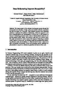
The majority of existing devices for three dimensional interaction have one end-effector that the user manipulates with his hand. They can be isotonic or isometric/elastic depending on their mechanical architecture. The latter are better for rate control rather than position control where the former are better, according to the experiments of Zhai [1]. For example, the PHANToM is an isotonic device that provides an intuitive interaction similar to everyday gestures through the manipulation of a stylus or thimble, and the SpaceMouse [2] is an elastic device to rate control objects in 3D. Devices for 3D interaction with one end-effector are integral as it is possible to move diagonally across dimensions as defined by Jacob et al. [3]. Nevertheless the user has no individual control on each DOF. If the user moves the device in one particular direction, the pointer will not go exactly in that direction due to human limb limitations. Rice et al [4] observed that controlling six DOF with one hand is difficult. Some teleoperation systems, such as the Shuttle Remote Manipulator require two-handed operation: one hand for rotation control and the other for translation control. In the same way, can we improve 3 DOF devices by subdividing them in multiple lower DOF near fingers? To evaluate DOF separation in 3D interaction, we have designed a new haptic device called the DigiHaptic proposing a novel interaction concept that consists of the separation and association of the degrees of freedom in an intuitive way to three fingers [5]. The device comprises three levers associated with the thumb, forefinger and ring finger as illustrated in figure 1. Each lever is connected to a DC-motor through a thread to provide force feedback or simulate behaviors such as springs on levers [6]. Depending on the motor command, the DigiHaptic can be used in isotonic and elastic mode with force feedback, and in isometric mode. In elastic mode, springs are simulated so as to always return the lever to a neutral position set at equal distances of the lever boundaries. Considering that the user handles each lever over a 60◦ range, this give 4cm of movement amplitude. Moreover it is possible to adjust spring stiffness from low to high depending on the user preferences. Although it is a separable device [3], the three DOF can be handled simultaneously. In each mode there is an isomorphism between fingers and object movements. Objects are translated according to the width of the screen (x axis) with thumb, the height of the screen (y axis) with the ring finger and the depth of the screen (z axis) with the forefinger1 . As there is a direct relationship between the fingers and the object’s movements, we hope to make the use of the device intuitive. Objects can also be rotated around the corresponding axis in rotation mode after pressing a switch on the device with the middle finger. In this paper, we only use the translation mode. In the same way the keyboard is a device with multiple separated end-effectors and the way a person playing a shooting game like Quake uses it shows that separated DOF can be used if arranged in an intuitive 1
In this paper, we use the following convention (OpenGL convention): x axis is from the viewer’s left side to the right side, y axis is the bottom up direction, and z axis is the direction the viewer facing
Fig. 1. The DigiHaptic
manner. In these games the ”w” and ”s” keys are used to move the character upward and backward and the ”s” and ”d” keys to move the character left and right. The DigiHaptic can be used mainly for navigation and manipulation tasks. Questions arise from its use, such as: Can the user coordinate the three levers simultaneously to perform a given task? Does the user perform better with individual control of each DOF? This paper presents here the DigiHaptic’s evaluation (using the elastic mode) and a comparison to the performance of the SpaceMouse (another elastic device) in three dimensional steering tasks - where a user moves a pointer along a predefined path in the workspace. In this first evaluation of the device, we used the two elastic devices in rate control mode to evaluate only the influence of DOF separation on the user’s performances. The SpaceMouse was also chosen because it is widely used in 3D softwares such as Catia or 3D Studio Max to control the camera position or to manipulate objects.
2 2.1
Method Experimental Task
The task involved steering in a 3D workspace. In the experiments, subjects were asked to move the 3D cursor (ring or ball) to the beginning of the path and then to steer the path. Participants had to minimize the time elapsed between the beginning and the end of the path and were urged to adjust their speed-accuracy strategy so as to avoid going beyond the path boundaries. There were three straight paths oriented in different directions we name respectively ”A” (path from the front side to the back side), ”B” (path from the left down front side to the right up back side), and ”C” (path from the left up side to the right down side) and three representations for each path we name respectively ”1” (thread with ring), ”2” (empty tube with the ball), and ”3” (filled tube with the ball) (fig.2). In all conditions, the cursor orientation was automatically oriented perpendicular to the path.
A
B
C
1
2
3
Fig. 2. The three straight paths (up) and the three path representations (down)
We wanted to start with easy paths before trying more complicated ones because subjects were not used to use 3D devices thus complicated paths would not have allowed us to distinguish between the influence of
DOF separation and the influence of learning time. That is why we chose three straight paths. The paths orientation were chosen to manipulate two or three DOF on the device to compare if users performed worse with simultaneous use of three DOF than two DOF. The different representations were used especially to ensure that results do not depend on the representation of the path but depend only on the coordination effect. The experiment was conducted with a desktop 3D virtual environment. In designing the 3D displays, several types of visual cues were chosen like linear perspective, interposition (edge occlusion), shadow of the 3D cursor and rings on the ground which help in the perception of the depth. Rings on the ground were placed at 33%, 66% and 100% of the path length to provide cues regarding the height of the path. We didn’t want to use stereo-glasses in this experiment as we wanted to place the subject in natural conditions (computer desktop). At the beginning of each trial, the 3D cursor (ring or ball) appeared at a random position in red. The subject was asked to bring it to the beginning of the path by matching the 3D cursor to a phantom and was helped by the straight line and the 3D cursor shadow represented on the ground. When the 3D cursor match the phantom, the subject start to steer the path. During the experiment the phantom, represented in a gray transparency, indicates the last position of the 3D cursor within the tube before it exited the path. It helps the user to know where he has to return the cursor in order to continue in the case he exits the path (fig. 3). When the 3D pointer’s center coincided with the path center, it became green. Then the further it went outside the path’s center, the darker it became. It became black when it touched the path boundaries (contact) and red when outside the path boundaries (fig. 4).
Fig. 3. The cursor in red outside the path and its phantom in gray into the path during a trial
2.2
Fig. 4. Cursor colors depending on cursors positions
Participants
A total of 23 subject volunteers, all normal sighted participated in the study. Most of the participants (19) were right-handed and 4 were left-handed. There were two different groups randomly separated for each device. All subjects used their right hand on both devices. None of the subjects was familiar with the task being investigated or the interface used in this study. None of the subjects had prior experience with the input devices. 2.3
Procedure
The subjects sat in front of the screen at a distance of approximately 70 cm. Tests started after nine warm-up trials. The entire experiment lasted one hour for each subject. Each combination of path and representation was tested with 9 trials. The trials were presented randomly. A dialog box explaining the task was presented at the beginning of the experiment. Subjects were instructed to perform the task as quickly and accurately as possible. The trial happens like described in section 2.1. The end of each trial was signaled with a short auditory beep and a dialog box indicating the remaining trials to perform. Subjects could thus take a short break before pressing a key to continue. The number of contacts, exits, steering time, total path length covered and deviations to the path center were recorded approximately every 20 to 30 ms. For each trial, the recording started after the user placed the cursor at the beginning of the path. A between-group design was used in this experiment.
2.4
Apparatus
The experiment was conducted on an Athlon Windows 2000 running a custom-built Visual C++/OpenGL application. The display was a 21-inch monitor, set to 1024x768 resolution. Two input controllers were used: a SpaceMouse Classic and a DigiHaptic used in elastic mode. Both devices were operated in rate control mode. For the DigiHaptic fixed spring stiffness were set on each lever and remained the same for all subjects. No additional force feedback was used on the device. To ensure a fair comparison between the two devices, we tuned the sensitivities for the two devices with two experimented users on each of them. We have chosen the average sensitivity for each device which leads to the lowest steering time on the whole paths.
3 3.1
Results and Discussion Steering Time
In this steering task experiment, we wish to compare the steering time to the index of difficulty of the path. The mechanics of 2D steering have been studied extensively by Accot and Zhai (e.g.[7–9]), who showed that performance can be predicted by an extension to Fitts’ Law called the Steering Law [7]. The Steering Law relates completion time to two factors: the length and width of the path. The performance equation is: A (1) W Where T is the completion time, a and b are constants, A is the length of the path, and W is its width. The constants allow consideration of the shape of the path (e.g. circular paths have higher constants than straight paths). The steering law has been shown to accurately predict completion time over several path types, input A devices, and task scales. W represents the index of difficulty of the path (ID). Finally, by analogy to Fitts’ law, the index of performance IP in a steering task is defined by IP = 1/b. This result is usually used for comparing steering performance between different experimental conditions. The index of difficulty depends on the path and its representation. The ID was calculated by the ratio between the path length (A) and the width (W) (Table 1). W was the path width effectively available for maneuvering. All the lengths taken correspond to the effective dimensions of objects in OpenGL units. T =a+b
Table 1. Table with the ID for each path and representation
A B C
1 77 100 72
2 12 15 11
3 12 15 11
For each path, the IDs are equal for the second and third representations as the tube and ball diameters are identical. In the first representation, the ring’s internal diameter is lower than the ball diameter, which explains the higher ID. Inevitably participants sometimes stray beyond the specified boundaries. In Zhai’s original work all trials with errors were disregarded, which is clearly subobtimal as it disregards what users were not able to do. If we compare a fast and unreliable device with a slow and reliable device and just use movement times, the outcome unreliable device will always win if we take only into account the correct trials, yet nobody can achieve anything with it. In the experiment, when the user exits the path, he has to bring back the cursor where he exited which gives a time penalty. So we used all trials to test the steering law. For the DigiHaptic, the steering law proved to hold at all representations with very good regression fitness. The models for steering time were for each representation (in ms) (2)(3)(4). 1 : T = −68174 + 1110 × ID r2 = 0.999
(2)
2 : T = −61416 + 6521 × ID r2 = 0.999 3 : T = −58621 + 6277 × ID r2 = 0.999
(3) (4)
As a result, the time performance for the DigiHaptic is the highest for the ring and thread (representation ”1”) while the two other representations are equivalent. Another point is that paths requiring the use of 2
DOF (”A” and ”C” paths) or 3 DOF (”B” path) are consistent in steering time compared to the ID of the path. i.e. using two or three fingers has no influence on the steering time. This represents the same difficulty for the user. For the SpaceMouse, the steering law does not hold for all representations and it is surprising (5)(6)(7). To investigate why, we will compute the coordination efficiency for each device and path in the next section. 1 : T = −24993 + 495 × ID r2 = 0.744 2 : T = −17382 + 2474 × ID r2 = 0.666
(5) (6)
3 : T = −18266 + 2524 × ID r2 = 0.745
(7)
Results of an analysis of variance (ANOVA) were consistent with the early analysis. The analysis design included the devices conditions (DigiHaptic and SpaceMouse) with repeated measures on the path and representation factors: 3 (path) * 3 (representation). The path factors had three categories: A, B and C (fig. 2). The representation factors had also three categories: 1, 2 and 3 (fig. 2). Analysis of variance (ANOVA) for mean task steering time revealed a significant effect of the devices (F(1,21)=5.734, p < 0.0260). Globally, the test shows that subjects perform the task faster for the SpaceMouse than for the DigiHaptic. The path factor (F(2,42)=70.291, p < 0.0000) has a significant effect on task performance. The results on the path show that the ”B” and ”C” paths require more time than the ”A” path both for the DigiHaptic and the SpaceMouse but for all paths they were better for the SpaceMouse. There is also a significant effect of the representation factor (F(2,42)=8.673, p < 0.0007). Significant effects were found for both two-way interaction devices * paths (F(2,42)=13.664, p < 0.0000) and paths * representations (F(4,84)=4.247, p < 0.0035). Figure 5 shows mean task steering time for each paths and devices.
Fig. 5. Mean task steering time (ms) for each path and devices
3.2
Fig. 6. Efficiency factor for the SpaceMouse and DigiHaptic versus paths
Coordination Measures
We want to compare how much the user can coordinate the three DOF on the two devices and thus compare whether the DOF separation leads to lower or better coordination. To quantify the DOF coordination, we used the notion of efficiency proposed by Zhai [10] that suppose that the highest DOF coordination is achieved between two points when the path followed is a straight line. Thus the amount of coordination is calculated by: ef f iciency =
Length of actual path − Length of shortest path Length of shortest path
(8)
The lower the efficiency coefficient is the more coordinated the device. To quantify the coordination for each device, we used the definition of efficiency presented above. Each time, we took the length covered by the user from the start to the end of the path, including the length covered when outside the path after an exit. For each path and representation, the SpaceMouse’s efficiency coefficient is always greater than the one of the DigiHaptic (fig. 6), which means there is less coordination on the SpaceMouse. There is no important difference between efficiency factors calculated for the three representations of each path.
The ”A” path is the most coordinated one. For the paths ”A” and ”B”, the results are similar for the two devices whereas for the path ”C”, there is a sharp difference between the two devices. It is surprising that for the SpaceMouse the coordination coefficient of the ”C” path is greater than the one of the ”B” path although the ”C” path is easier than the ”B” path. We can hypothesize that the ”C” path is responsible for the fact that the SpaceMouse does not fit the steering law. Users had difficulty coordinating the action of pushing down the motion controller while going to the right. If we compare the ”A” and ”C” paths both require the use of two DOF, the ”A” path get better results for the DigiHaptic and SpaceMouse. We can hypothesize that this is due to the lower slope on the ”A” path. For the ”B” path, the DigiHaptic is at its least efficiency because the path requires the use of the three DOF at the same time. 3.3
Exits
Figure 7 shows the mean number of exits for each path (A, B and C) with each device. The ANOVA analysis for mean task exits indicates that there is a main effect of path (F(2,42)=76.811, p < 0.0000). For ”A” and ”B” paths, the average number of exits is similar for the two devices. Globally, the subject exits more with the ”B” path as it is more difficult to coordinate 3 DOF at the same time. One more time, we observe a large difference between the DigiHaptic and the SpaceMouse for the ”C” path that concerns this time the average number of exits: users exit more with the SpaceMouse for the ”C” path. Indeed there are a significant interaction effects devices * paths (F(2,42)=6.090, p < 0.0047). These results were consistent with coordination results that implies a coordination problem with width axis (”x”) and the height axis (”y”) for the SpaceMouse.
Fig. 7. Mean number of exits for each path and device
3.4
Fig. 8. Mean number of contacts for each path and device
Contacts
Figure 8 shows mean number of contacts for each path and device. The ANOVA on the average number of contacts indicated that there were a significant effect of the path (F(1,42)= 48.444, p < 0.0000). Significant interaction effects were found for device * path (F(2,42)= 6.017, p < 0.0050). Finally, there were no significant three-way interactions. The mean number of contacts shows that the ”A” path is better than the ”B” and ”C” paths. For the ”B” path, the average number of exits for the DigiHaptic and SpaceMouse was similar whereas the average number of contacts is more important for the DigiHaptic. We could have expected that the number of exits would have been proportional to the number of contacts. This could imply that the DigiHaptic allows a good control when path boundaries are reached. The average number of contacts are similar for the DigiHaptic and SpaceMouse for the ”C” path whereas we observed that an average number of exits was more important with the SpaceMouse than the DigiHaptic for the ”C” path. The results suggest that there is a rate control problem on the SpaceMouse together with the previously discussed coordination problem. We could hypothesize that the rate control problem comes from the low movements amplitude of the motion controller.
4
Conclusion
First of all, the main result is that the DigiHaptic conception allows simultaneous coordination of separated DOF. Otherwise, we have seen that the coordination of two or three DOF leads to the same steering time compared to the ID of the path. Certainly, we have seen that the DOF separation increase the steering time, nevertheless the DOF separation appears to increase the control on the 3D pointer. For the paths where the number of contacts are similar for the DigiHaptic and the SpaceMouse, the number of exits is more important with the SpaceMouse, and where the number of contacts is more important on the DigiHaptic, the number of exits keeps similar for the two device. So the DOF coordination difficulty that increase the steering time is compensated by a better correction and adjustment of the trajectory. The coordination efficiency is better on the DigiHaptic than on the SpaceMouse. We believe this is due to the original and ergonomic design of the DigiHaptic because there is a direct relationship between the fingers and cursors movements. These results can also be explained because the DigiHaptic is more elastic than the SpaceMouse. Thus the DigiHaptic affords richer proprioceptive feedbacks which leads to a better control. In the same way, Poulton indicated that for tracking tasks, spring-loaded controls were best for compensatory tracking in a position control system with a slow ramp target to track [11]. The problem found on the SpaceMouse between the ”x” and ”y” axis needs further analysis to be deep understood. We have noticed that users keep their wrist motionless. For the movement involved, subjects have to perform a translation movement with the motion controller. Nevertheless the motion controller affordance implicates an involuntary rotation movement. In future works, we plan to repeat the same study on other more complicated paths to see if the results keep consistent with this study and check if there are other coordination problems with the SpaceMouse.
5
Acknowledgements
This work has been carried out within the framework of the INRIA Alcove project and is supported by the IRCICA (Institut de Recherche sur les Composants logiciels et mat´eriels pour l’Information et la Communication Avanc´ee).
References 1. Shumin Zhai. Human Performance in Six Degree of Freedom Input Control. PhD thesis, University of Toronto, 1995. 2. Spacemouse http://www.spacemouse.com. 3. R.J.K. Jacob, L.E. Silbert, C. Mcfarlane, and M.P. Mullen. Integrality and Separability of Input Devices. ACM Transactions on Computer-Human Interaction, 1(1):3–26, March 1994. 4. J.R. Rice, J.P. Yorchak, and C.S. Hartley. Capture of satellites having rotational motion. In Human Factor Society 30th Annual Meeting, 1986. 5. G. Casiez, P. Pl´enacoste, C. Chaillou, and B. Semail. The DigiHaptic, a New Three Degrees of Freedom Multi-finger Haptic Device. In Proceedings of Virtual Reality International Conference, pages 35–39, May 2003. 6. G. Casiez, P. Pl´enacoste, C. Chaillou, and B. Semail. Elastic Force Feedback with a New Multi-finger haptic device: The DigiHaptic. In Proceedings of Eurohaptics, pages 121–134, July 2003. 7. J. Accot and S. Zhai. Beyond Fitts’ Law: Models for Trajectory-Based HCI Tasks. In Proc. of CHI’97, pages 295–302, 1997. 8. J. Accot and S. Zhai. Performance Evaluation of Input Devices in Trajectory-Based Tasks: An Application of The Steering Law. In Proc. of CHI’99, pages 466–472, 1999. 9. J. Accot and S. Zhai. Scale Effects in Steering Law Tasks. In Proc of CHI’01, pages 1–8, 2001. 10. S. Zhai and P. Milgram. Quantifying Coordination in Multiple DOF Movement and Its Application to Evaluating 6 DOF Input Devices. In Proc. of CHI’98, pages 320–327, 1998. 11. E.C. Poulton. Tracking skill and manual control. New York: Academic Press, 1974.