International Journal of Computer and Communication Engineering, Vol. 3, No. 4, July 2014
Double Phase Modular Steganography Using Error Images of Lossy Wavelet Transforms Masoud Afrakhteh and Jeong A. Lee Abstract—An error image of Lossy Wavelet Transform differentiates a typical cover image from its wavelet transformed cover image which is resulted from applying a desired image compression factor (ICF) to the respective cover image. The proposed method uses such error images for finding where and to what extent a target pixel in a cover image must hold secret bits. The method is also able to embed maximal embedding rates on gray-scale cover images, up to four bits per pixel (bpp), preserving a human vision-imperceptible PSNR value and less detectability. The detectability level is shown by Ensemble classifiers using second order SPAM as their input features. Additionally, the method embeds minimal rates, up to one bpp, while being roughly as undetectable as state-of-the-art schemes such as HUGO (highly undetectable stego) and EA (edge adaptive). Index Terms—Error image, JPEG image compression rates, ensemble classifier, information hiding, steganography.
I. INTRODUCTION Steganography conceals the very existence of secret information in terms of bits. It usually embeds secret data into some type of digital cover media, such as image, video, audio, or the like. The manipulated image or video looks innocent, and the message cannot be detected with the human eye. On the other hand, exposing the existence of any hidden information in a cover image is what steganalysis does. Such steganalytic algorithms are able to estimate the probable existence of secret bits in different ways. If steganalysis detects hidden information with a minimum probability of error, the steganographic scheme is broken. There are two factors that have to be considered in designing a modern steganographic scheme, namely embedding rate and undetectability, with a trade-off between them. The higher the embedding rate, the greater is the detectability. Some approaches are more concerned about embedding capacity, with higher imperceptibility levels provided by greater peak signal-to-noise ratio (PSNR) values, but there are many that aim to be more undetectable rather than having higher PSNR values. Least significant bit (LSB) replacement [1] embeds information in the LSB of a pixel, independently of its value. The LSB is directly replaced by the secret bit. This adds some unwanted statistical artifacts, by which the existence of secret bits can be exposed. Such artifacts are paired with values in a histogram of the stego image created by the LSB replacement method. This makes detection easier for a Chi-square attack [2]. LSB matching Manuscript received January 23, 2014; revised March 10, 2014. The authors are with the Computer Systems Laboratory, Chosun University, Korea (e-mail:
[email protected],
[email protected]).
DOI: 10.7763/IJCCE.2014.V3.338
294
(LSBM) [3] applies minor changes after LSB replacement, because it randomly increments or decrements the LSB of a pixel according to a pseudo random number generator (PRNG), if the secret bit does not match the pixel’s LSB. Unlike LSB replacement and LSBM, which deal with the pixel values independently, LSB matching revisited (LSBMR) [4] modifies the LSBM algorithm in such a way that the choice of incrementing or decrementing the pixel value is no longer random. It performs the operation by using a pair of pixels as a unit. The first pixel value changes in such a way that one secret bit is saved in its LSB, and the second secret bit equals a function of the two modified pixel values. Both LSBM and LSBMR are undetectable with a Chi-square attack because, statistically, the probability of change is the same as that of the increment/decrement performed, either randomly or by using a function. Although the asymmetry artifacts of LSB replacement are almost completely avoided, they can still be detectable using stronger steganalytic attacks. These LSB-based approaches do not consider the difference between the pixel and its neighbors. Edge adaptive (EA) image steganography [5] embeds secret bits based on the LSBMR method. It begins embedding from the edge regions as much as possible, while keeping other smooth areas as they are. The maximum embedding capacity of this approach is limited to one bpp while the visual quality and security of stego images prove to be better than LSB-based and edge-based methods. Another approach is using high-dimensional image models to perform HUGO [6]. This method calculates distortions corresponding to modification of each pixel by ±1 and sets the stego image pixel value as the minimum of these numbers. The best embedding order starts from pixels with the highest to lowest cost of embedding, which is ascertained by an additive distortion measure. Security is evaluated by training SVM (support vector machine)-based steganalyzers using second-order subtractive pixel adjacency model (SPAM) features [7]. A filter suppresses the stego image content and exposes the added noise in the stego image. Dependencies between neighboring pixels are modeled as a higher-order Markov chain. The resulting sample transition probability matrix is a vector feature that is a SPAM of covers. The second-order Markov chain results in a second SPAM including 686 features for a typical stego image. Finally, the undetectability level of the mentioned methods is benchmarked utilizing the second SPAM as input features to ensemble classifiers [8]. They prove to have better performance compared to SVM-based steganalyzers in terms of both time and accuracy. The classifier has to be trained with a database of pictures to detect information more accurately, so BOSS (break our steganographic system) version 1.01 was used to create sufficiently many stego images. The BOSS database consists
International Journal of Computer and Communication Engineering, Vol. 3, No. 4, July 2014
of 10,000 8-bit grayscale images of size 512 × 512 pixels. On the other hand, in classical steganography, multiple base notational system (MBNS) [9] segments the secret bits into several partitions of the same size (32 bits) and applies a modular function to alter the cover image. Thien and Lin [10] also proposed an LSB-based scheme to hide four bpp in a 512 × 512 host image based on a modulus operation. Such classical steganographic schemes can embed up to four bpp, while HUGO and EA cannot. The classical methods are fully detectable by ensemble classifiers; however, they can be less detectable to a Chi-squared attack, a completely outdated steganalysis method. The current work embeds in the spatial domain owing to the simplicity of the algorithmic nature and ease of mathematical analysis. In addition, spatial-domain techniques can carry the largest messages (embedding rate) compared to transform domains [11], because transformation domain techniques can embed only in nonzero coefficients, whereas all pixels can be utilized in the spatial domain. Modern steganographic schemes are intended to be undetectable, rather than stressing the PSNR value, so the current scheme is also shown to be more undetectable while it can even embed more than one bpp. With classical steganography, the proposed method embeds up to the maximum reported embedding capacity of four bpp [10]. The algorithm has some similarities to the MBNS method, although the bases are calculated in a different way. This paper is organized as follows. Section II describes the proposed method. The experimental results are compared and evaluated with respect to modern and classical steganographic schemes in Section III. Finally, Section IV highlights and discusses the conclusions, based on the results.
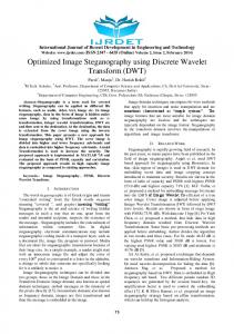
compression factor (ICF), such as the one suggested in Joint Photographic Experts Group (JPEG 2000) compression. 1) Apply a wavelet transform to the cover image. The cover image can be transformed using a JPEG ICF, a real value greater than one specifying the target compression ratio, defined as the ratio of input image size to output compressed size. For example, a value of 2.0 implies that the output image size will be half of the input image size or less. A higher value implies a smaller file size and reduced image quality. 2) After the wavelet transform is applied, the matrix of coefficients is scalar-quantized to reduce the number of bits representing them, at the expense of quality. The reduction level factor (RLF) has minimum and maximum values of one and eight, respectively. 3) The compressed image resembles the original image with some imperceptible added noise. The amount of noise has a direct relation to compression level and embedding rate. The larger the embedding rate, the more noise. 4) The noise becomes greater if a greater ICF is used. In this regard, for every pixel𝑖,𝑗 from CoverImg𝑀×𝑁 where i M and j N:
Error Im gi, j Cover Im gi , j Compressed Im gi , j (1) According to the pixel values from the error image, multiple bases are calculated for every corresponding pixel. 𝐵𝑎𝑠𝑒𝑀×𝑁 represents the matrix of multiple bases: ( Error Im gi , j 1) Basei , j log 2 OEF
For embedding rates up to one bpp, the optimal extension fields (OEF) factor is equal to zero. It does not increment unless the embedding rate is between two and four bpp. The entire procedure is illustrated in Fig. 1 and described in two phases as below:
II. PROPOSED METHOD The proposed method pre-processes the cover image sized M × N pixels in order to create an error image. The required error image is computed by applying a suitable image 121
124
120
121
123
123
126
121
119
136
156
138
126
130
130
132
−
(2)
117
120
125
123
119
124
128
124
127
135
141
139
129
135
138
135
=
4
4
-5
-2
4
-1
-2
-3
-8
1
15
-1
-3
-3
-8
-3
2
2
2
1
2
1
1
2
3
1
4
1
2
2
3
2
Cover Image Compressed Image using ICF Error Image Calculated Base Matrix Fig. 1. Process of calculating Base matrix for 4×4 pixels of a typical cover image (OEF = 0).
Phase 1: The secret bits are partitioned into non-overlapping 32-bit blocks. The decimal value 𝐷 of every block is represented using a corresponding pseudorandom number RND. Vector 𝐷′ saves the conversion of D into the base of RND and includes a list of integer values. RND is computed using a PRNG and the desired embedding rate, which is measured in bpp; RND increases for higher embedding rates: EmbRate EmbRate 32 RND ( PRNG 1) 10 2 2 8 8
they are. Thus, only pixels with a base greater than or equal to two may be embedded. Using the decimal values of every element of vector 𝐷′ , one can convert every decimal value into the multiple-base notational system [9]. Thus, vector 𝐷′′ keeps conversion(s) of every decimal value from vector 𝐷′ into n multiple bases. The embedding is applied in two ways: ′′ Case 1: For every element of vector 𝐷′′ , say 𝐷𝑙≤𝑛 , greater than or equal to two, directly change the pixel value using the following reversible formulation:
(3)
Cover Im gi , j Dl" " (4) Stego Im gi , j Basei , j Dl Base i, j
Phase 2: The algorithm reads the corresponding Base from 𝐵𝑎𝑠𝑒𝑀×𝑁 according to the embedding order, which is line-by-line from top-to-bottom of the cover image. Pixels with a Base value less than two are skipped and left the way
𝐷𝑙′′ can easily be extracted by dividing the stego image pixel value into the corresponding Base value of the same pixel. 295
International Journal of Computer and Communication Engineering, Vol. 3, No. 4, July 2014
Case 2: For every 𝐷𝑙′′ whose value is either zero or one, LSBMR [4] is applied to minimize the embedding effect for two pixel units. Note that, in contrast to the LSB matching
concept, there might be some pixels between two such pixels to which LSB matching is not applied.
Fig. 2. Structure of the proposed embedding method.
The structure of the proposed scheme is modeled in Fig. 2. Phases 1 and 2 are repeated for every pixel from the cover image. If some of the secret bits have not been embedded yet, ICF must be increased towards 10,000. If the secret bits are still partially embedded, the OEF must be incremented until the secret bits are embedded completely. The following algorithm extracts the secret bits from the stego-image:
Make two pixel units Set M1 to the LSB of the 1st pixel Set M2 to the function of 1st and 2nd pixels as proposed in the LSBMR approach Let M be M1 and M2 in order Increment SumBases with M × MulBases Add MulBases× Base to MulBases If SumBases plus MulBases is greater than RND then Increment SumRndBases with SumBases× Rn𝑑𝐵𝑎𝑠𝑒𝑠 Add RndBases× 𝑅𝑁𝐷 to RndBases If SumRndBases plus RndBases is greater than the maximum decimal value of a block of 32 bits then Set NextBlock to True Show binary form of SumRndBases as part of the secret bits extracted Initialize SumRndBases to 0 Initialize RndBases to 1 Else Initialize SumBases to 0 Initialize MulBases to 1 Until payload is extracted completely
Get Base matrix, Payload, PRNG seed number, ICF and OEF Set NextBlock to True Initialize SumRndBases and SumBases to 0 Initialize RndBases and MulBases to 1 Repeat the following for every pixel of the stego image If the Corresponding Base value of the current pixel is ≥ 2 then If NextBlock is true then Calculate RND according to the given payload size and PRNG Set NextBlock to False Set Bases and RndBases to 1 Set SumBases and SumRndBases to 0 Let M save the remainder of the division of the stego pixel value into its corresponding Base value If M is either 0 or 1 then
Phase 1
TABLE I: A NUMERIC ILLUSTRATION OF EMBEDDING AND EXTRACTING. 1st 32-bit block 0...00000001101001 1st block Corresponding RND Number: 100 Decimal Value 105 = (15)100 = 5 + 1 ×100 5 =(12)4,3 = 2+ 1 ×3 1 = (1)2 =1 𝐷′ = {5 ,1}
Phase 2
𝐷𝑙′′ = {2, 1, 1}
1
1
Pre-Processing Phase
Cover Image
80
87
101
157
165
Base numbers
0 No Embedding No Embedding No Extracting
3
1 No Embedding No Embedding No Extracting
4
2
-
-
157
165
Initialization
Embed If 𝐵𝑎𝑠𝑒 ≥ 2
Extraction
if Case 1: 𝐷𝑙′′ Stego ≥2 Image if Case 2: 𝐷𝑙′′