1584
OPTICS LETTERS / Vol. 29, No. 14 / July 15, 2004
Double random-phase encoding in the Fresnel domain Guohai Situ and Jingjuan Zhang Department of Physics, Graduate School of the Chinese Academy of Sciences, P.O. Box 3908, Beijing 100039, China Received March 15, 2004 A lensless optical security system based on double random-phase encoding in the Fresnel domain is proposed. This technique can encrypt a primary image to random noise by use of two statistically independent random-phase masks in the input and transform planes, respectively. In this system the positions of the significant planes and the operation wavelength, as well as the phase codes, are used as keys to encrypt and recover the primary image. Therefore higher security is achieved. The sensitivity of the decrypted image to shifting along the propagation direction and to the wavelength are also investigated. © 2004 Optical Society of America OCIS codes: 070.2580, 070.4560, 100.1160, 050.1940, 260.1960.
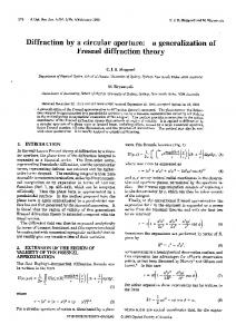
Optical techniques have shown great potential in the f ield of information security.1 – 11 Réfrégier and Javidi1 proposed a double random-phase encryption technique that encodes a primary image into stationary white noise. The two random-phase masks placed in the input and the Fourier plane of a 4-f correlator serve as the keys to the system. This technique was also put forward for use in encrypting information in the fractional Fourier domain with various architectures.3 – 6 It is well demonstrated that higher security is then promised because the scale factors and the fraction orders of the fractional Fourier transform provide additional keys. Matoba and Javidi11 also used this technique for encrypted data storage in the Fresnel domain and experimentally demonstrated that the positions of the phase masks can be used as additional keys. The double random-phase encoding technique can be further applied in a more f lexible and more compact way, in which the wavelength can also be regarded as a key: the much simpler optical security system proposed in this Letter. Compared with previous techniques,1 – 6,11 this system is lensless, which minimizes the hardware requirement (i.e., the expensive Fourier lens) and is easier to implement. The optical setup of the system is shown in Fig. 1. Three planes are defined as the input plane, the transform plane, and the output plane. The distances between adjacent planes are z1 and z2 . The first random-phase mask (RPM1 ) attached to primary image f 共x, y兲 is located in the input plane. The second random-phase mask (RPM2 ) is located in the transform plane. When the system is perpendicularly illuminated with a plane wave of wavelength l, the encrypted image is obtained at the output. Distance parameters z1 and z2 are determined according to the size of the aperture to satisfy the Fresnel approximation. The distributions in the adjacent planes are related by a Fresnel transform with respect to z1 , l, and z2 , l. Thus the wavelength can be used as a key of the system besides the phase codes1,2 and their positions.11 The key space is signif icantly enlarged, and higher security is consequently achieved. For convenience, we denote the coordinate systems of the input, the transform, and the output plane to be 共x, y兲, 共x0 , y 0兲, and 共x0 , y0 兲, respectively, and the 0146-9592/04/141584-03$15.00/0
distributions of RPM1 and RPM2 to be exp关 j f共x, y兲兴 and exp关 j c共x0, y 0兲兴, respectively, where f共x, y兲 and c共x0 , y 0 兲 are statistically independent white sequences in 关0, 2p兴. Under the Fresnel approximation,12 complex amplitude u共x0 , y 0 兲 obtained in the transform plane is expressed as follows: ZZ f 共x, y兲exp关 j f共x, y兲兴 u共x0 , y 0 兲 苷 3 h共x0 , y 0 ; x, y; z1; l兲dxdy ,
(1)
where h共x0 , y 0 ; x, y; z1 ; l兲 苷
exp共 j 2pz1兾l兲 jlz1 æ Ω jp 0 2 0 2 3 exp 关共x 2 x兲 1 共 y 2 y兲 兴 lz1 (2)
is the impulse response (IR) of the f irst stage of the system. It is essentially the Fourier transform of the transfer function.12 For simplicity, we rewrite Eq. (1) in the form of u共x0 , y 0兲 苷 FrTl 兵 f 共x, y兲exp关 jf共x, y兲兴; z1其 ,
(3)
where FrTl represents the Fresnel transform with respect to l. Then u共x0 , y 0兲 is multiplied by RPM2 and totally Fresnel transformed to the output to obtain the encrypted image as g共x0 , y0 兲 苷 FrTl 兵u共x0 , y 0 兲exp关 jc共x0 , y 0 兲兴; z2 其 .
(4)
It is easily seen by substitution of Eq. (3) into Eq. (4) that g共x0 , y0兲 is a function with respect to
Fig. 1.
Optical setup of the proposed security system.
© 2004 Optical Society of America
July 15, 2004 / Vol. 29, No. 14 / OPTICS LETTERS
exp关 j f共x, y兲兴, exp关 jc共x0 , y 0兲兴, z1 , z2 , and l. Obviously, as in the conventional methods in Refs. 1 and 2, the phase code exp关 jc共x0 , y 0兲兴 provides information for decryption. Moreover, in the present case, given the same primary image f 共x, y兲 and the same phase codes, a different group of 共z1 , z2 , l兲 can result in a different distribution for the encrypted image. Therefore these three parameters can be used as additional keys. Since the inverse Fresnel transform does not optically exist, the complex conjugation of g共x0 , y0 兲 should be used for decryption. The optical setup for decryption is the same as that for encryption but in the reverse direction. That is, the input of the decryption system is the output of its counterpart. The complex conjugation of the encrypted image, gⴱ 共x0 , y0兲, can be easily generated in the input plane of the decryption setup through phase conjugation in a photorefractive crystal3 in which the encrypted data are stored. Then gⴱ 共x0 , y0 兲 is Fresnel transformed to the transform plane: v共x0 , y 0 兲 苷 FrTl 关gⴱ 共x0 , y0 兲; z2 兴 .
(5)
Then v共x0 , y 0 兲 is multiplied by RPM2 . Finally the product is Fresnel transformed to the output and the following decrypted image is obtained: fˆ 共x, y兲 苷 FrTl 兵v共x0 , y 0 兲exp关 j c共x0, y 0兲兴; z1 其 .
(6)
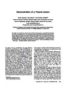
By substituting Eq. (5) into Eq. (6), we can show that j fˆ 共x, y兲j 苷 f 共x, y兲. Since f 共x, y兲 is a positive function, the square modulus of the decrypted image j fˆ 共x, y兲j2 obtained at the output by a CCD yields the information about f 共x, y兲. Clearly, unlike in the conventional techniques,1,2 it is exp关 j c共x0 , y 0 兲兴 but not exp关2jc共x0 , y 0 兲兴 that serves as the key. This property can be used to avoid the diff iculty of fabrication of the precise complex conjugation of exp关 j c共x0 , y 0 兲兴. Computer simulations are performed to verify the validity of the proposed technique. Since the architecture is lensless, the beam propagating through the system may be somewhat divergent, and the f ield sizes of the significant planes must be mismatched. Hence z1 and z2 should be chosen carefully to reduce the size mismatch regarding the propagation distance. Near-field diffraction is preferred in particular. Further, the size of the encrypted image should be less than that of the recording medium so as to eliminate the power loss. Thus the primary image is embedded into a background window in the simulations. As shown in Fig. 2(a), the image of interest is a 128 3 128 pixel picture of a jet plane embedded in a window. The size of the window is chosen to be 256 3 256 pixels to perform the angular spectrum propagation algorithm based on a fast Fourier transform,13 which is efficient for near-f ield diffraction calculation with high accuracy. The procedure is as follows: Compute the Fourier transform (angular spectrum) of the input signal, then multiply it by the transfer function, and finally compute the inverse Fourier transform of the product. The actual sizes of the windows and the phase masks are 4 mm 3 4 mm. z1 and z2 are 20 and 30 mm, respectively, to ensure that the Nyquist sampling condition12,13 is satisf ied and that all the
1585
significant encrypted information is restricted within the recording window. Wavelength l of the input plane wave is 600 nm. The encrypted image is shown in Fig. 2(b), which indicates that the image of interest is encoded into a noiselike signal. When all the keys are available, the decrypted image closely resembles the primary image. However, decryption without knowledge of these keys is ill posed and requires a random search in an infinite key space. To evaluate the inf luence of the keys to the decryption performance, the mean square error (MSE) is usually used. However, the signal-to-noise ratio (SNR) can enhance the quality difference measured by the MSE. Furthermore, it is easier to determine the image quality from the SNR because it directly gives the relative power ratio between the signal and the noise.14 The SNR of fˆ 共x, y兲 on a logarithmic scale is def ined as RR Ω æ 关 f 共x, y兲兴2 dxdy , SNR 苷 10 log RR (7) 关 f 共x, y兲 2 j fˆ 共x, y兲j兴2 dxdy RR where 关 f 共x, y兲 2 j fˆ 共x, y兲j兴2 dxdy gives the information about the MSE in essence. The SNR value for the image decrypted with all the correct keys is approximately 650 dB. Such a high value is obtained in an ideal system without noise, misalignment, and phase error. It is a positive number less than 100 dB for a practical optical system in general. However, when a wrong phase code is used for decryption, the SNR of the blind retrieved image is only approximately 238.4 dB in our simulation instance. This implies that the signal of interest immerges into the random noise and cannot be detected. Now assume that the phase code is correct. If the correct l, z1 , and z2 are used for decryption, the phase code contributes little to the decrypted image. Otherwise, the random noise introduced by the RPMs cannot be removed completely by use of the phase code because the incorrect l, z1 , or z2 might affect the IR of the system. Let us assume that the decryption wavelength is Dl from the encryption wavelength, then the IR of the f irst stage of the decryption system becomes exp关 j 2pz2 兾共l 1 Dl兲兴 j 共l 1 Dl兲z2 æ 关共x0 2 x0 兲2 1 共 y 0 2 y0 兲2 兴 .
h共x0 , y 0 ; x0 , y0 ; z2, l 1 Dl兲 苷 Ω 3 exp
jp 共l 1 Dl兲z2
(8)
Fig. 2. (a) Primary image for computer simulations and (b) encrypted image.
1586
OPTICS LETTERS / Vol. 29, No. 14 / July 15, 2004
is analogous in this case. Clearly the SNR of j fˆ 共x, y兲j decreases as Dl increases. The relation between them is plotted in Fig. 3, which indicates that the SNR is sensitive to Dl. The SNR drops steeply to 0 when Dl increases to approximately 5 nm. Analogously, the RPMs shifting axially from the corresponding matched positions might introduce noise to the decrypted image by convolving with gⴱ 共x0 , y0 兲 and exp关 jc共x0 , y 0 兲兴, as well as contributing a constant phase. The SNR versus the axial shifting Dz is plotted in Fig. 4, in which we fix the distance between the input and the output plane to be z1 1 z2 苷 50 mm and shift RPM2 for simplicity. Obviously the SNR decreases as Dz increases, and the decrypted image is more tolerant to the axial shifting. To summarize, we have proposed a lensless optical security system that encrypts a primary image to random noise by use of two statistically independent random-phase codes located in the input and the transform plane of the system. The distributions in these two planes and the output plane are related by Fresnel transform. The distance between these planes and the wavelength parameters, as well as the phase code, serves as the key to the system. Computer simulations were carried out to support this concept.
Fig. 3. Behavior of the SNR versus Dl.
The authors appreciate the anonymous reviewers for their constructive comments. This work was supported by the National Natural Science Foundation of China under grant 60277027. G. Situ’s e-mail address is
[email protected]. References
Fig. 4. Behavior of the SNR versus Dz.
Note that 1 1 Dl . 苷 2 l 1 Dl l l共l 1 Dl兲
(9)
The first phase factor exp关 j2pz2 兾共l 1 Dl兲兴 of Eq. (8) can be expressed as exp关 j 2pz2 兾l兴 exp关2j2pz2 Dl兾 l共l 1 Dl兲兴. That is, the effect of Dl is to add a phase exp关 j 2pz2Dl兾l共l 1 Dl兲兴 to the phase distribution in the transform plane. Through similar analysis, we can show that the second phase factor, exp兵 j p关共x0 2 x0 兲2 1 共 y 0 2 y0 兲2 兴兾共l 1 Dl兲z2 其, affects the distribution in the transform plane by convolving with gⴱ 共x0 , y0兲. Thus the application of the phase code cannot remove the random phase introduced by Dl. This additional random phase is further amplified after being Fresnel transformed to the output by the second stage of the decryption system. The analysis
1. P. Réfrégier and B. Javidi, Opt. Lett. 20, 767 (1995). 2. N. Towghi, B. Javidi, and Z. Luo, J. Opt. Soc. Am. A 16, 1915 (1999). 3. G. Unnikrishnan, J. Joseph, and K. Singh, Opt. Lett. 25, 887 (2000). 4. B. Zhu, S. Liu, and Q. Ran, Opt. Lett. 25, 1159 (2000). 5. S. Liu, L. Yu, and B. Zhu, Opt. Commun. 187, 57 (2001). 6. B. Hennelly and J. B. Sheridan, Opt. Lett. 28, 269 (2003). 7. P. C. Mogensen and J. Glückstad, Opt. Lett. 25, 566 (2000). 8. X. Peng, L. Yu, and L. Cai, Opt. Express 10, 41 (2002), http://www.opticsexpress.org. 9. G. Situ and J. Zhang, Optik 114, 473 (2003). 10. G. Situ and J. Zhang, Opt. Commun. 232, 115 (2004). 11. O. Matoba and B. Javidi, Opt. Lett. 24, 762 (1999). 12. J. W. Goodman, Introduction to Fourier Optics (McGraw-Hill, New York, 1968). 13. D. Mendlovic, Z. Zalevsky, and N. Konforti, J. Mod. Opt. 44, 407 (1997). 14. D. G. Manolakis, V. K. Ingle, and S. M. Kogon, Statistical and Adaptive Signal Processing (McGraw-Hill, New York, 2000).