May 19, 2000 - tured by so called activator-inhibitor models [2] describ- ing the dynamics of ..... A. Doelman and A. van Harten, (Longman, Burnt Mill,. 1995).
Drifting Pattern Domains in a Reaction-Diffusion System with Nonlocal Coupling Ernesto M. Nicola, Michal Or-Guil, Wilfried Wolf and Markus B¨ar
arXiv:nlin/0005043v1 [nlin.PS] 19 May 2000
Max-Planck-Institut f¨ ur Physik komplexer Systeme, N¨ othnitzer Straße 38, D-01187 Dresden, Germany (May 19, 2000) Drifting pattern domains (DPDs), i.e. moving localized patches of traveling waves embedded in a stationary (Turing) pattern background and vice versa, are observed in simulations of a reactiondiffusion model with nonlocal coupling. Within this model, a region of bistability between Turing patterns and traveling waves arises from a codimension-2 Turing-wave bifurcation (TWB). DPDs are found within that region in a substantial distance from the TWB. We investigated the dynamics of single interfaces between Turing and wave patterns. It is found that DPDs exist due to a locking of the interface velocities, which is imposed by the absence of space-time defects near these interfaces. PACS numbers: 03.40.Kf, 47.54.+r, 82.40.Ck 80
- Introduction - Pattern forming processes in nonequilibrium systems can be classified according to the primary instability of the spatially homogeneous state. Ref. [1] distinguishes three basic types of instabilities in unbounded systems: (i) spatially periodic and stationary in time, (ii) spatially periodic and oscillatory in time and (iii) spatially homogeneous and oscillatory in time. Within the reaction-diffusion literature, these instabilities are known as Turing, wave and Hopf bifurcation, respectively.
(a)
t 400 0
60
120
(c)
(b)
Many chemical and biological patterns are well captured by so called activator-inhibitor models [2] describing the dynamics of two reacting and diffusing substances with two coupled partial differential equations. In such two component reaction-diffusion models only Turing and Hopf instabilities are possible. Recently, numerical investigations of chemical reaction-diffusion systems with three components [3] and nonlocal coupling [4] have yielded the occurrence of wave instabilities and the corresponding patterns. A universal description of patterns near these instabilities is achieved within the framework of amplitude equations [1,5].
0
180
40
0
30
60
90
0
x
0
30
60
90
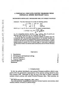
FIG. 1. Space-time plots of the field u in grey scale for three examples of DPDs found in numerical simulations of Eqs. (1). In all three cases a = 6.0, and only a part of the system of length L = 409.6 is shown. (a) Large DPD with δ = 0.84. (b),(c) DPDs consisting of a single cell of Turing and wave respectively. In (b) δ = 0.80 and in (c) δ = 0.91. Other parameters, see [17].
Here, we study a simple FitzHugh-Nagumo model with inhibitory nonlocal coupling that is obtained as a limiting case of a three component reaction-diffusion system. It describes the interaction of an activator species with an inhibitor. For slow inhibitor diffusion (compared to the activator diffusion), the model exhibits wave instabilities, while, for fast inhibitor diffusion, Turing instabilities are found. The two instabilities occur simultaneously at a codimension-2 Turing-wave bifurcation (TWB). Such a situation has been found earlier within a model for binary convection [6] and is a generalization of the well investigated Turing-Hopf instability in reaction-diffusion systems [7]. Basic properties of a TWB have been studied theoretically in amplitude equations [8] as well as experimentally in a one-dimensional gas-discharge system [9]. In our model, we find a pattern previously unknown in
reaction-diffusion systems: drifting pattern domains (DPDs), i.e. localized patches of traveling waves embedded in a Turing background and vice versa (see Fig. 1). These patches have constant width and move (drift) with constant speed. As they drift along, maxima of the concentrations of activator and inhibitor are conserved beyond both boundaries of the DPD, where Turing and wave patterns are joined together. Consequently, formation of space-time defects by coalescence of maxima and minima is prevented. Similar patterns have been reported in a variety of hydrodynamical experimental systems, see e.g. [10,11] and have been related to secondary instabilities (parity breaking) of stationary patterns [10,12]. DPDs exist in a broad region of the para1
def
1
0.5
(a)
(b)
0.5
0
0
ω /5 −kTc −kWc
kWc
point u0 =(u0 , v0 )T = (0, 0)T for all parameter values. Here, we consider the regime where this fixed point is the only one present, i.e. a < bc/d + 2µ/σ and consider perturbations ∝ eikx−λ(k)t , where λ(k) = χ(k) + iω(k). The growth rates λ(k) are given by the eigenvalues of the Jacobian. Linear stability analysis reveals that Eqs. (1) exhibit wave instabilities if the nonlocal coupling is of sufficiently long range σ < σc = (2µ/(1 + δ))1/3 . In the following we vary the control parameters a and δ; the ,,driving force” a represents the kinetics, whereas the ratio of diffusion coefficients δ describes the spatial coupling in the medium. All other parameters of Eqs. (1) have been fixed [17]. For the wave bifurcation, c the critical wavenumber kW and parameters aW , δW are c obtained from the condition λ(kW ) = ±iω0 where the c perturbation with k is the fastest growing mode with W q
kWc
kTc
χ 0
σ
1
σ
2
C
−0.5
−2
k0
2
c FIG. 2. (a) Critical wavenumber kW against inverse nonlocal coupling range σ. (b) Real (χ) and imaginary part (ω) of λ(k) at the TWB, for parameters see [17].
meter space, but appear only in a substantial distance to the onset of pattern formation. Their existence region is characterized by bistability between waves and Turing patterns. Near the boundary of DPD existence small DPDs containing only a single wave or Turing ,,cell” inside a background of the respective other state are encountered (see Figs. 1b,c). Outside the DPD existence region, the width of pattern domains shrinks or expands; these transient domains exhibit defects at the interfaces. Large DPDs are composed of two interfaces separating wave and Turing patterns. In this Letter we will study the dynamics of such interfaces. These interfaces typically select the wavenumber of the invading domain and form one parameter families characterized by the wavenumber of the invaded domain. Far away from the TWB, interfaces can exhibit a locking mechanism of their velocities due to the absence of defects. This locking implies that the interface velocity is fixed by the wavenumbers and frequency of the patterns that they separate. If both interfaces in a DPD are locked, they have to travel with equal speed. This mechanism is responsible for the existence of DPDs with constant width. - Model equations and linear stability - We study a variant of the FitzHugh-Nagumo equation supplemented by an inhibitory nonlocal coupling in the dynamics of the activator u
2µσ 2 c 2 (kW ) = 1+δ − σ . Note, that for both σ = σC and σ = 0 (global coupling limit) the critical wavenumber c is kW = 0, see Fig. 2a. Similarly, a competing Turing instability appears for a critical parameter aT with a wavenumber kTc , where the leading eigenvalue λ(kTc ) = 0. For large enough driving a, the wave instability appears for small δ, while for large δ the Turing instability destabilizes the homogeneous state. For the chosen parameter values, the system exhibits a TWB point (see Fig. 3a and [17]). For the corresponding λ(k), see Fig. 2b. - Weakly nonlinear analysis - Near the TWB, we can def write u =(u, v)T as a perturbative expansion around u0 using a small parameter ε, indicating the distance to the instability threshold: u = u0 + εu1 + ε2 u2 + ε3 u3 + · · · and use the following multiple scale ansatz: [18] c
This leads to a set of coupled equations for the amplitudes A, B and R for left-, right-going waves and Turing pattern that depend on slow time and space variables. After reestablishing the original time and space variables and performing further ε-independent scaling, one obtains:
∂t u = au + βu2 − αu3 − bv + ∂x2 u Z +∞ ′ ′ ′ −µ e−σ|x−x | u(x , t)dx
∂t R = ηR − |R|2 R + ξ∂x2 R − ζ(|A|2 + |B|2 )R ∂t A + cg ∂x A = ρA + (1 + ic1 )∂x2 A − (1 − ic3 )|A|2 A
−∞
∂t v = cu − dv + δ∂x2 v.
c
u1 = [A(X,T1,T2)UA ei(ω0 t+kW x) + B(X,T1,T2)UB ei(ω0 t−kW x) c +R(X,T1,T2)UR eikT x + c.c.]/2.
(1)
−g(1 − ic2 )|B|2 A − ν(1 − iκ)|R|2 A ∂t B − cg ∂x B = ρB + (1 + ic1 )∂x2 B − (1 − ic3 )|B|2 B
Eqs. (1) represent a limiting case of a three variable model involving the activator u, the inhibitor v and an additional fast inhibitor [13]. Related three variable models have been introduced previously to describe pattern formation on sea shells and in cell biology [14] as well as spot dynamics in gas discharges [15] and concentration patterns in heterogeneous catalysis [16]. Here, the emphasis is on the onset of pattern formation resulting from destabilization of a single homogeneous steady state. Eqs. (1) possess the trivial homogeneous fixed
−g(1 − ic2 )|A|2 B − ν(1 − iκ)|R|2 B. (2) For the detailed values of all coefficients, see [19]. Note, that the nonlocal term of Eqs. (1) only enters into the diffusion coefficients of Eqs. (2) and does not give rise to a nonlocal term in Eqs. (2). Knowledge of the coefficients of Eqs. (2) allows analytical predictions of the pattern dynamics. Here, traveling waves are always preferred over standing waves (g > 1, see [1]) and bistability 2
between wave and Turing patterns is found (νζ > 1). In this bistability region in parameter space (see Fig. 3a), a family of stable Turing patterns and two families of stable left- and right-traveling waves parametrised by their corresponding wavenumbers coexist. To get further insight, we take a closer look at the dynamics of single interfaces separating domains of Turing and wave patterns. - Interface dynamics. - With suitable initial conditions, a moving interface between Turing and wave patterns will be formed in simulations of Eqs. (1). We can distinguish two types of interfaces depending on whether the phase velocity of the waves points towards the interface or away from it. This classification is independent from the direction in which the interface is moving. In the following, we will call the first type inward-interfaces and the second outward-interfaces. Fig. 3b and 3c show examples of the latter type. Near the TWB, we have studied general properties of such interfaces in amplitude equations (3) by counting arguments [5] as well as by direct numerical simulations. Counting arguments are applied to ordinary differential equations obtained from a coherent structure ansatz in a comoving frame. We observe that, typically, the wavenumber of the invaded domain remains constant, while it adapts in the invading domain. In other words, the interface selects a particular wavenumber for the invading state, while the initial wavenumber of the invaded state is a free parameter. The velocity of the interface is a function of this parameter. For Turing patterns the selected wavenumber is always the critical sel c one, i. e. kTsel = kTc , while for waves typically kW 6= kW sel and therefore ω 6= ω0 . This is valid for both inwardand outward-interfaces. Thus, we typically have two oneparameter families of interfaces for a given point in parameter space. These results are confirmed by numerical simulations of the nonlocal model (1) near the TWB. Simulations of interfaces in Eqs. (1) far away from the TWB, show qualitatively similar behavior with respect to the selected wavenumbers. In addition, interfaces far away from the TWB may exhibit a locking mechanism of their velocities, which are fixed by the wavenumbers and frequencies of the Turing and wave domains. More specifically, the selected velocity is determined by the absence of defects at the interface. For geometrical reasons an interface without defects, that connects a wave state with wavenumber kW and frequency ω and a Turing state with kT , has a speed |vlock | = ω/(kT −kW ). This velocity locking mechanism is found for both types of interfaces. Two examples of areas where locking occurs (locking tongues) in parameter space for inward- and outward-interfaces are given in Fig. 3a. A locked outward-interface is displayed in Fig. 3b. Outside the tongue the outwardinterfaces display phase slips (see Fig. 3c). The area of the locking tongues depends only weakly on the front parameter kW for inward-interfaces and kT for outwardinterfaces. Note, that the locking tongues open at a sub-
6.0
AC
(a) 5.5
OT
a
IT bistability
5.0 wave
4.5
no patterns
0.6
0.8
δ
1
(b)
(c)
60
60
30
30
Turing
1.2
1.4
50
100
t 0
0
50
100
x
0
0
FIG. 3. (a) Parameter space a-δ near the TWB point (black circle). The light grey region indicates bistability bec tween the Turing and wave pattern with kTc , kW as predicted from Eqs. (2). Dark grey regions correspond to two examples of locking tongues for an outward-interface with kT = kTc c (region OT) and an inward-interface with kW = kW (region IT). These two tongues are shown only up to a ≈ 5.6. The dashed lines show where the selected velocities of interfaces in Eqs. (2) coincide with vlock . White circles indicate parameter values of simulations shown in (b) and (c). See Fig. 4 for a description of the dashed regions. (b) and (c) show space-time plots of u in grey scale from simulations of Eqs. (1) showing outward-interfaces for a = 5.2. In (b) an example inside the locking tongue is shown for δ = 0.80 and in (c) an interface outside the tongue exhibiting defects (inside the white circles) for δ = 0.86 is shown.
stantial distance from the TWB. Since the rapidly varying space and time scales have been factored out in the amplitude equations (2), locking tongues cannot be found therein. However on a line in the parameter space (see Fig. 3a), the velocity of interfaces in Eqs. (2) coincides with the velocity prescribed by the locking mechanism. The locking mechanism arises when the characteristic width of the interfaces is of the same order than the characteristic length scale of the patterns. - DPDs and their Phase Diagram. - Consider that a large DPD is composed of an inward-interface and an outward-interface, that practically do not interact (see e.g. Fig. 1a). If both interfaces exhibit no defects and are locked, their velocities have equal magnitude |vlock | but opposite signs. This ensures constant width and allows construction of DPDs of arbitrary size. Indeed, the region of existence of large DPDs starts to open where the locking tongues for both interface types begin to overlap (see Fig. 3a). This is the case for a > ∼ 5.7. Above that 3
8
7
A B
systems, which do not simply combine two homogeneous states, but, instead, select their constituents from whole families of possible traveling or stationary periodic patterns.
C
a 6
bistability
5 wave
0.6
0.8
δ
no pattern
1
[1] M. C. Cross and P. C. Hohenberg, Rev. Mod. Phys. 65,851 (1993). [2] A. S. Mikhailov, Foundations of Synergetics I, (Springer Verlag, New York, 1990). [3] A. M. Zhabotinsky, M. Dolnik and I. R. Epstein, J. Chem. Phys. 103, 10306 (1995). [4] M. Hildebrand, A. S. Mikhailov and G. Ertl, Phys. Rev. Lett. 81, 2602 (1998). [5] M. van Hecke, C. Storm and W. van Saarloos, Physica D, 134, 1 (1999). [6] W. Sch¨ opf and W. Zimmermann, Phys. Rev. E 47, 1739 (1993). [7] J. J. Perraud et. al., Phys. Rev. Lett. 71, 1272 (1993); A. De Wit et. al., Phys. Rev. E 54, 261 (1996); M. Meixner et. al., Phys. Rev. E 55, 6690 (1997); M. Or-Guil and M. Bode, Physica A 249, 174 (1998). [8] D. Walgraef, Phys. Rev. E 55, 6887 (1997). [9] H. Willebrand et. al., Contrib. Plasma Phys. 31, 57 (1991). [10] J. M. Fleselles, A. J. Simon and A. J. Libchaber, Adv. Phys. 1, 1 (1991). [11] C. Counillon et. al., Phys. Rev. Lett. 80, 2117 (1998). [12] R. E. Goldstein et. al., Phys. Rev. A 43, 6700 (1991). [13] Eqs. (1) are obtained from the three variable system ∂t u = au + βu2 − αu3 − bv − gw + ∂x2 u; ∂t v = cu − dv + δ∂x2 v; τw ∂t w = eu − f w + γ∂x2 w in the limit τw = 0. The parameters characterizing p the nonlocal coupling p in Eqs. (1) are then found as σ = f /γ and µ = g e2 /γf . [14] H. Meinhardt and M. Klingler, J. Theor. Biol. 126, 63 (1987); H. Meinhardt, J. Cell. Sci. 112, 2867 (1999). [15] C. P. Schenk et. al., Phys. Rev. Lett. 78, 3781 (1997), M. Or-Guil et. al., Phys. Rev. E 57, 6432 (1998). [16] M. Sheintuch and O. Nekhamkina, J. Chem. Phys. 107, 8165 (1997). [17] We chose the parameters b = 4, c = d = 1, σ = 1 and µ = 2, α = 4/3 and β = 0. All results have been checked for β 6= 0 and do not change qualitatively as long as |β| √ is not too large. The TWB point√is found at aT W = 4 2 −√1 and δT W = 1 with kTc =√ 23/2 − 1 ≃ 1.352, c kW = 21/2 − 1 ≃ 0.644 and ω0 = 2. [18] Note that two new time scales (T1 ∝ εt and T2 ∝ ε2 t) are needed. For a detailed discussion see E. Knobloch, in Pattern Formation in Complex Dissipative Systems, eds. A. Doelman and A. van Harten, (Longman, Burnt Mill, 1995). [19] At the TWB point for the parameters given in [17] the coefficients of Eqs. (2) are cg = 1.1892, c1 = 0.8536, c3 = 1, g = 2, c2 = 1, ν = 1/2, ζ = 8, κ = 1 and ξ = 4.4142. The small parameters in Eqs. (2) are defined c 2 by ρ = [((a − aT W ) − (kW ) (δ − δT W )]/2 and η = 2[(a − aT W ) + (kTc )2 (δ − δT W )/2].
Turing
1.2
FIG. 4. The region of existence of DPDs obtained in simulations of Eq. (1) in the a-δ parameter space shown dashed. The light grey area corresponds to the bistable region between the critical wave and Turing patterns as calculated from the amplitude equations (3). In region B DPDs of any size exist; the size being determined only by the initial condition. In region C small domains of wave patches traveling in a Turing background are found. In region A only Turing-droplets are stable. The three circles correspond to the location of simulations shown in Fig. 1.
value, DPDs spontaneously form from a variety of initial conditions. We have determined the parameter region, where they propagate with constant width and drift speed, from extensive simulations in systems with sizes L > 400 and periodic boundary conditions. The results are shown in the phase diagram of Fig. 4. We can distinguish three different subregions. In region B, DPDs of any size, with two locked interfaces traveling at the same speed, are found (see Fig. 1a). In region A, the inward-interface is no longer locked and its speed is smaller than |vlock |. Therefore large domains of Turing (wave) patterns contract (expand) in size until only a stable DPDs containing a single Turing cell is left (see Fig. 1b). In region C, the outward-interface selects a sel kW which would be unstable against Turing patterns in an infinite domain. Therefore, the wave domain forming the DPD is mostly replaced by a Turing pattern. However, small DPDs with a few wavelength of wave pattern are still encountered. At the outer boundary of region C, only DPDs with a single wave cell are found to be stable (see Fig. 1c). - Conclusion - We found a large variety of drifting pattern domains in a reaction-diffusion model with nonlocal coupling. Their ingredients include a bistability between wave and Turing patterns near a codimension-2 point as well as absence of defects at the interface. They exist as robust patterns only in a finite distance to the onset of pattern formation. Our results are not limited to the reaction-diffusion model studied here and should carry over to other physical systems with similar pattern forming instabilities. Altogether, DPDs and their constituting interfaces represent a generalization of simpler structures such as fronts and pulses in bistable reaction-diffusion 4