DRILLING SAFER WITH CUTTING EDGE TECHNOLOGIES BY. SAVING ... This allows the use of a well profile which has significantly reduced surface and intermediate .... Upper and lower parts are connected to communicate hydraulically.
1 of 9
DRILLING SAFER WITH CUTTING EDGE TECHNOLOGIES BY SAVING TIME AND COST S. Masi, C. Molaschi, S. Haiz, T. Eren eni e&p Abstract Much technological advancements in drilling technology have been made through many years of research and development. The applications of these advancements are varied, but the purpose of their use is always the same: to minimise the NPT, thus safely reaching the planned target while saving time and money. This paper will present some of the new drilling technologies that have been recently developed in the oil industry. In particular, it will focus on technologies that have been proven to be extremely efficient when conducting drilling operations in very challenging scenarios. The “Lean Profile” is a redefinition of the well profile based on a drastic reduction of the existing clearance between casing outer diameter and the diameter of the hole where the casing has been run. This allows the use of a well profile which has significantly reduced surface and intermediate section sizes while not changing the final production casing and tubing diameters. The lean well profile reduces the drilling time (smaller sections can be drilled faster), reduces the production of cuttings as well as the subsequent need for disposal and also improves the efficiency of cementing operations. Ceramic centralisers are used to facilitate casing running operations and to reduce friction while drilling. The E-CD continuous circulating system allows continuous mud circulation while drilling and making pipe connections. The main advantage of this system is the ability to drill in conditions where there is a very narrow margin between pore and fracture gradient. As a result of the continuous mud circulation, bottom hole pressure is kept constant and almost equal to the pore pressure. This ensures that there are no pressure peaks due to interruptions of mud circulation which increases the risk of formation fracturing (or ballooning effects). The E-CD system can be used as a stand alone system or in combination with other equipment as a sub-system of the E-NBD. E-NBD is a closed-loop system which keeps bottom hole pressure balanced with pore pressure by analysing mud flow rates and detecting inflows or losses into the well-bore. Well pressures are controlled at the surface by a rotating BOP and a computerised choke system.
Introduction Lean Profile technology, E-CD and E-NBD applications are globally being implemented in various projects of eni e&p. Their applications proved safer and efficient drilling practices are achievable; not only for routine drilling activities but for drilling projects those of which are difficult to be finalized without the use of innovative technologies (Calderoni et al 1999). Lean Profile is an innovative drilling technique which aims to maintain a very small clearance (e.g. 1 in.) between the casing strings. The reduced clearances result in having slimmer wellbores simultaneously keeping production casing string at the conventional diameters. The key factor in achieving the success of the Lean Profile application is based on having a smooth well trajectory. Application of the Lean Profile technology has resulted in drilling smaller diameter wellbores, thus handling half of the rock volume supposed to be drilled with conventional methods. This innovative
2 of 9 technology not only results in handling reduced drilling cuttings but also increases the efficiency of the drilling time in comparison to conventional methods. Interrupting circulation to make up or breakout a connection may create problems since resuming a circulation may need significant annular pressures which in turn may result in fracture of formations and consequently kicks into the wellbore (Calderoni and Girola 2009). Drilling of wells with narrow pore and fracture gradient margins become more challenging without the utilization of the continuous circulation. A steady state condition is maintained downhole so that the formations do not suffer pressure oscillations when the wellbore is under continuous circulation. Well cleaning, and other activities such as pumping out are also improved when the wellbore is under continuous circulation. During recent decades the abilities to apply continuous circulations when conventional jointed work strings are present have been significantly improved.
Lean Profile The slimmer casing profile with reduced hole diameters and clearance between bore hole wall and casing, called “Lean Profile” is based on the following terms: Having a smooth well trajectory Use of Flush (or Near-Flush) casing joint connections A smooth well trajectory can be achieved by means of utilizing an automatic drilling system. Automatic Drilling Systems are efficiently being used all around the world in today’s drilling applications. Their efficiency and reliability are proved to be suitable in achieving perfectly drilled wellbores. Lean Profile has been applied in both vertical and directionally drilled wells. The main advantages of the lean profile applications are as outlined below: Better Drilling Performance: This is a direct consequence of the less drilling cuttings generation. Experience showed that drilling time in Lean Profile applications can be reduced up to 40%. Less Material Consumption: A slimmer wellbore requires less material for casing, drilling fluids, cementing and other materials e.g. additives. Lower Environmental Impact: The less the drilling fluids used the less the waste material to be disposed (including the waste material transportation needs). Improved Cementing: The cementing operations are improved as a result of smaller wellbores, as washouts are less frequent. The hydraulics during displacements of slurries is also more efficient due to the reduced clearance between the borehole and the casing string. Reduced Risk of Stuck Pipe: Drilling a smooth hole with a BHA that is composed of only one or two reamers reduces the risk of stuck pipe occurrence due to the elimination of key seats because of the hole geometry. Also in an event of hole collapse, the probability of having the cuttings/cavings forming a stuck point around the restrictions in the wellbore between the drillstring and borehole wall will be reduced. Reduced Risk of Drillstring Failures: As a consequence of no pipe rotation for steering control in vertical wells the risk of downhole tools failures are reduced. For deviated wells, the increased ROP implies a decrease of drilling time. Besides, well side force and load distribution are more uniform. Improved Safety: The casing wear reduction in vertical wells and the improvement of load conditions in deviated wells have a direct impact on safety during drilling operations. Wells drilled with Lean Profile Technology are concluded in considerably less days than
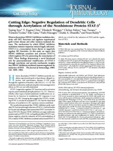
3 of 9 conventionally drilled ones. The economical impact of the Lean Profile Technology is considerable if compared to conventional drilling applications. From an economical point of view, the following observations can be made, related to Lean Profile technology: The additional cost for the use of automatic drilling systems are nearly paid by the cost saving of less material consumed and less cost requirements for waste management. The drilling time saving of the Lean Profile Technology application is the most significant economical issue. Operatively, the Lean Profile is based on a minimum clearance between borehole wall and casing, which depends on the quality of the trajectory and the gauge of the bore hole. High doglegs, well tortuosity and reduced gauges due to hole stability problems require a larger clearance to ensure proper running of the casing to the bottom. eni e&p realized an enormous potential for savings by optimizing the drilling and completion process. Based on the features of an automated steering tool, plus using nearly flush casing connections, the traditional well profile was replaced by a slimmer shape. Automatic drilling technologies allow reducing the clearances between the hole and the casing outer diameters. The term ‘Lean Profile’ was established by Eni-AGIP for this new optimized drilling concept. Figure 1 illustrates the hole diameter and casing diameter difference between a conventional well profile, the “Lean Profile”, and the contingency. In addition to the reduced wellbore diameters being drilled, the lean profile technology can even provide a reduced number of casing sections.
Figure 1 – Lean profile versus conventional well.
Preferred Geological Areas for Beneficial Performance Areas such as complex structure of formations with randomly distributed geological settings, with high horizontal stresses, steep beds, numerous faults and alternating rock hardness sequences are the preferred area for the application of Lean Profile Technology. Together with high dip angles the
4 of 9 mentioned geological parameters result in excessive oscillations of the bore hole trajectory, if equipment with non-adequate steering behaviour is used. Further drilling problems are generated by the non-uniform stress distribution in such areas. As a bore hole is drilled, the hydraulic pressure of the drilling mud is not able to support the bore hole wall in the way the original rock column did. Consequently, rock surrounding the bore hole is distorted or strained and may fail if the redistributed stresses exceed the rock strength. Such hole stability problems are creating breakouts, and the debris to enter the bore hole leading to cleaning problems, stuck pipes or even hole collapse. Additionally in-gauge sections, which are normally also present in such complex formation structures, demand reaming operations. These will once more deteriorate the bore hole stability and hinder tripping and running casing. Because hole stability problems are a function of time and hole diameter, there should be an interest to drill as fast as possible with the smallest diameter allowing the completion capabilities across the production level. System Technology and Functionality The Automatic Drilling System represents an automatic steerable downhole motor integrating basic MWD features. The drilling path is controlled by a variable-gauge stabilizer located on the motor bearing assembly close to the drill bit. The internal downhole electronics controls both the steering means and the sensors. Monitoring of the tool function downhole and drilling data is enabled via positive pulse mud data transmission. Automatic Drilling System was primarily developed to overcome insufficient drilling performance and increase hole quality of a borehole. The continuously activated steering function is applied in the sliding mode. The downhole closed loop system to adjust the programmed drilling direction requires no interference from the surface. Thus the directional drilling process is tremendously simplified, even if the formation has a strong build up tendency. Each time the internal sensor detects a deviation from the planned trajectory the steerable stabilizer is activated to push back the drill bit on the requested borehole course. The result of this automated steering is a perfect smooth hole within an inclination tolerance under 0.1°. Automatic Drilling System was developed for the hole sizes of 12 ¼“ and 16“, later on the fleet was completed to serve also the 14 ¾“, 17 1/2“ and 22“ hole sections. Basically the downhole tool consists of a mud powered downhole motor to drive the drill bit, a slightly modified motor bearing assembly supporting the hydraulically forced expandable stabilizer to provide steering capacity on the lower end, and a control sub housing the electric and hydraulic control, power supply and mud pulse transmission system. Upper and lower parts are connected to communicate hydraulically. Provided with the capacity to operate at a maximum temperature of 150°C, the downhole electronics above the motor section also contains the two accelerometers delivering the necessary steering data. Due to the high accuracy of the sensor system and the very stiff tool configuration, this placement provides fully accurate steering, but allows to build a simple and reliable design.
Continuous Circulation Interrupting mud circulation to make-up or break-out drill pipes connections might result in undesired consequences; that could be more or less severe depending on the downhole pressures, on the geomechanical characteristics of the crossed formation and on well geometry. For example: when using heavy drilling fluids with a very high solids content, barite sagging could occur; in horizontal or highly deviated wells, cuttings removal may become insufficient; hole instability might occur due to pressure fluctuations when circulation is stopped and then re-established; in high
5 of 9 temperature wells, variations of the bottom hole temperature may be significant, etc. With a continuous circulation system in place, downhole steady-state conditions can be maintained so that pressure oscillations would not impact on the drilled formations. Well cleaning is improved, and the ability to pump out of hole for extended intervals, until the string is inside the previous casing, implies the reduction of pressure or stability problems in the open hole sections. The benefits of continuous circulation have been appreciated by the drilling industry when using coiled tubing, which has proved to be a valuable alternative in several well conditions; however, the use of coiled tubing drilling is limited by equipment restrictions. The benefits deriving from the application of continuous mud circulation to conventional jointed pipes can be summarized as follows: Quality Improvement of hole conditions Fewer stuck pipe incidents Prevention of ballooning effects Well Control/Safety Reduction of kicks likelihood Enabling Technology Drilling through “difficult” formations Narrow pore/fracture pressure gradients drilling Maximised potential for HP-HT, low head & underbalanced operations.
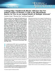
ENBD System The ENBD System (Figure 2) is the combination of two items: the E-CD System (1); an Active Choke System (2).
Figure 2 – “Eni Near Balance Drilling” System.
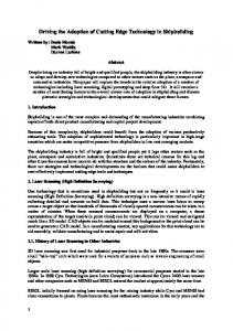
6 of 9 E-CD System The E-CD System is composed of two parts: the E-CD Subs and the E-CD Manifold. The E-CD Sub (Figure 3) is a dual flapper tool with a side entry port, which is run in hole screwed on top of drill pipe stands. The number of required subs depends on the borehole length to be drilled with uninterrupted circulation. Subs have a working pressure of 5,000 psi and 7,500 psi (imposed by the classification of the E-CD Manifold in use), and are available as conventional 4 1/2” IF and 5 1/2” FH connections, as well as other more recent connections (e.g., GP-HT55 and GP-XT57). The OD of the 5” E-CD Sub is 7” in the lower portion and 6 3/4” in the catch area for the top drive back-up tong; all the other dimensions indicated above are 7” OD all along the body. The minimum ID of all E-CD Subs is 71 mm (2 13/16”).
Figure 3 – E-CD sub.
The E-CD Manifold (Figure 4) is installed on the rig floor, and is used to divert flow from the stand pipe manifold directly to the side entry port of the E-CD Sub.
7 of 9
Figure 4 – E-CD manifold.
A hose connects the E-CD Manifold to the E-CD Sub on the rig floor, thus allowing a connection to be made without significant change from a normal connection. The E-CD System can be installed on every existing rig, whichever using the conventional Rotary Table or the Top Drive System. Minor modifications are required at the time of the very first installation (Figure 5). Installation of the manifold can be completed during NPT’s, such as after the cementing of a casing or at the end of a hole section which precedes the one requiring continuous circulation. Some limitations might arise on very small rigs, where the rig floor space does not allow the easy accommodation of the E-CD Manifold; a dedicated version of the E-CD Manifold is available to face this issue.
Figure 5 - E-CD Manifold 5000 psi WP - Layout of installation on the rig floor.
Active Choke System Through continuous monitoring of flow rates in and out of the well, the Active Choke System immediately and automatically adjusts the mud flow out of the well through a dedicated choke. It allows to: Drill a well, using a pre-defined backpressure or bottom hole pressure
8 of 9 Detect influxes on floater rigs with the same accuracy as on fixed rigs Identify circulation losses at an early stage. Among the available systems on the market, preference should be given to those capable of detecting micro fluxes. ENBD vs. MPD
ENBD advantages compared with the conventional MPD system are: 1) Equivalent Circulating Density (ECD) compensation through a surface backpressure is not necessary anymore during pipe connection. This allows avoiding any possible mistake during the transitory phase, where the surface backpressure is increased or decreased by following step-up/step-down charts. 2) Connection time is reduced, since the transitory phases are not necessary anymore. 3) There are no bottom hole temperature variations and, therefore, changes in mud rheological properties those might be generated during pipe connection are avoided. This improves the control of the ECD. 4) In high-temperature wells, temperature-related stresses on electronic components of downhole tools are significantly reduced thanks to the continuous cooling effect of mud during pipe connection. This allows extending the life of downhole tools (MWD/LWD) in HT environments. 5) Real-time monitoring of downhole parameters, e.g. downhole annular pressure (ECD), bottomhole circulating temperature, etc., can be carried out also during pipe connection. 6) It is possible to continue monitoring the drilling gas data during pipe connection: there is no need to wait for the stabilization of the gas trend before performing connection operations. 7) A gas influx can be safely circulated out while monitoring the ECD trend during pipe connection, without waiting for the bottom-up before making the connection. 8) Should it be necessary to replace a worn-out bearing insert of the Rotating Control Head, this operation can be carried out while maintaining full circulation in the wellbore, using the automatic choke manifold to control the wellbore pressure, thus reducing the risks of well pack-off and stuck pipe incidents.
Conclusions Lean Profile technology is being successfully applied in various operations of eni e&p. The applications are not limited to development projects but also applied for wildcat explorations. As a matter of fact, designing wells with smaller clearances between open hole and casing OD results in having slimmer wellbores, and therefore rigs with smaller capacities can be used. Drilling applications using Lean Profile Technology are observed to be have been drilled more efficiently and in a cost effective manner. The use of Lean Profile Technology applications are considered to increase. ENBD applications have also been applied in various operations of eni e&p. The continuous circulating system introduced with E-CDTM and Active Choke System in order to generate an ENBD system achieved successful outcomes facing several drilling on the limit cases, drilling of which would not be possible with the ENBD. It is considered that ENBD is a significant step in the way to effectively meet the needs to be able to drill inside narrow pore pressure and fracture gradients.
9 of 9
References Calderoni, A., Ligrone A., and Molaschi C.: “The Lean Profile: A Step Change in Drilling Performance”, SPE/IADC 52788, 1999 SPE/IADC Conference Amsterdam, Holland, 9-11 March 1999 Calderoni, A., and Girola G.,: “ENBD, the proprietary Eni Managed Pressure Drilling with Uninterrupted Mud Circulation: Technical Update after the First Year’s Activity”, IPTC 13867, International Petroleum Technology Conference, Doha, Qatar, 7-9 December 2009 Calderoni, A., Donati F., Maestrami M., Oppelt J., and Kruger S.: “From Lean to Extreme-Lean Well Profile: Field Experience in the Mediterranean Sea”, SPE Drilling & Completion Journal, March 2010, pp 19-26
Acknowledgements The authors would like to thank eni Headquarters and eni Foreign Affiliates for the authorization to present the paper.
Republic of Iraq Mini tn· of Oil •
ir t aq Oil and Gas Conference 26-27/ 10 /2011( d
p~lI'ed b~-
:-
P(lhol(lUln Research 4.:~. Devel0I>lnent Center Secrehll'Y of the cOllf(lrence E-Inail :I>rdc200"' ~ 'I>rdc.goY.iq www·l>rdc.go\'.iq ~~~~~~~~
IOGe
_________ ~
ff
II.lq
epubJic of Iraq l\'Iinistry• of Oil
First Iraa Oil and Gas Conference 26-27 / 10/ 2011( 1st lOGe
Prepared b~- :Pe-tl'ole-uJn Re-se-arch & De-ve-1ol))ne-nt Ce-nte-l' Se-cre-tary of the- confe-I'e-uceE-Inail :J)rdc200-,ra~I)J· dc.20Y.iq
Iraq
First Iraq Oil And Ga Conference 1
T
I
PRDC/2011
Republic of Iraq
Ministry of oil
1st Ir