Feb 18, 2005 - Thomas Franke, Jan Kierfeld and Xinzhao Zhang. Max-Planck-Institute of ...... [26] Geoghegan M and Krausch G 2003 Prog. Polym. Sci. 28 261.
INSTITUTE OF PHYSICS PUBLISHING
JOURNAL OF PHYSICS: CONDENSED MATTER
J. Phys.: Condens. Matter 17 (2005) S537–S558
doi:10.1088/0953-8984/17/9/015
Droplets, bubbles, and vesicles at chemically structured surfaces
Reinhard Lipowsky1 , Martin Brinkmann2 , Rumiana Dimova, Thomas Franke, Jan Kierfeld and Xinzhao Zhang Max-Planck-Institute of Colloids and Interfaces, 14424 Potsdam, Germany
Received 24 November 2004 Published 18 February 2005 Online at stacks.iop.org/JPhysCM/17/S537 Abstract Liquid droplets, gas bubbles, and membrane vesicles which are in contact with chemically structured substrate surfaces can undergo morphological transitions or shape transformations. The structured surfaces considered here consist of two types of surface domains, γ and δ, which attract and repel the droplets, bubbles, and vesicles, respectively. For droplets on a striped γ domain, one has to distinguish droplets with fixed end caps from those with freely moving end caps. Both types of channels undergo morphological wetting transitions. For vesicles, one has a strong adhesion regime in which the vesicle shapes have constant mean curvature and exhibit effective contact angles. One can then map the shape bifurcation diagram for vesicles onto the one for droplets if one includes the constraint of fixed membrane area. We also report preliminary experimental observations of the adhesion of vesicles to chemically structured surfaces. (Some figures in this article are in colour only in the electronic version)
1 http://www.mpikg.mpg.de/th/. 2 Present address: IRI c/o IEMN, F-59652 Villeneuve d’Ascq, France.
0953-8984/05/090537+22$30.00
© 2005 IOP Publishing Ltd
Printed in the UK
S537
S538
R Lipowsky et al
Glossary: List of symbols A Aad Aαβ Ame Aσβ α β δ �P γ κ λB λc L L αβσ L ch Lγ L st M Mco
be ρex ρin Rco Rve me T θ θδ θγ θeff θp v V Vβ Vin Vsp w W
area adhesion or contact area of vesicle surface area of αβ interface total membrane area of vesicle contact area of β droplet with σ substrate fluid bulk phase liquid phase which forms wetting layer lyophobic surface domain which is dewetted by the β phase pressure difference: droplets, �P ≡ Pα − Pβ ; vesicles, �P ≡ Pex − Pin lyophilic surface domain which is wetted by the β phase bending rigidity of membrane de Broglie wavelength critical wavelength of channel perturbations line tension of contact line length total length of contact line for a droplet lateral extension of channel diameter of circular γ domain and width of striped γ domain lateral extension of striped γ domain mean curvature contact mean curvature shape function for pressure difference �P of vesicles particle number density in exterior compartment particle number density in interior compartment contact curvature radius effective membrane radius defined by membrane area tension membrane tension temperature (in energy units) contact angle contact angle on δ surface contact angle on γ surface effective contact angle of adhering vesicle contact angle along pinned contact line segment reduced and dimensionless volume volume volume of β droplet volume of interior vesicle compartment volume of sphere reduced and dimensionless adhesion free energy density adhesion free energy density of vesicle
Droplets, bubbles, and vesicles at chemically structured surfaces
S539
1. Introduction Liquid droplets, gas bubbles, or lipid vesicles which are brought into contact with a substrate surface attain certain shapes which reflect the molecular interactions between these colloidal structures and the underlying substrate. These interactions can be modified by chemical and/or topographical patterning of the substrate surface. A relatively simple example is provided by surfaces which contain two types of surface domains, γ and δ, which attract and repel the droplets, bubbles, or vesicles, respectively. In the case of droplets (or bubbles),such chemically structured surfaces lead to morphological wetting (or drying) transitions at which the wetting layer changes its shape or morphology in a characteristic and typically abrupt manner [1–3]. Many experimental methods have been developed by which one can prepare chemically structured substrates with a variety of lyophilic and lyophobic surface domains. The linear size of these surface domains can be varied over a wide range of length scales from the millimetre down to the nanometre regime [4–10]. So far, morphological wetting transitions have been directly observed in the millimetre and micrometre regime but should also occur for surface domains with nanometre dimensions if one includes line tension effects. This paper is organized as follows. In section 2, we briefly review morphological wetting transitions on chemically structured substrates; more extended reviews are given in [11, 12]. We emphasize generic features for wetting of such substrate surfaces and focus on the relatively simple example of striped surface domains. In section 3, we extend our theory to the adhesion of vesicles. We focus on the strong adhesion regime and show that strongly adhering vesicles exhibit shapes which are similar to wetting droplets. The corresponding shape evolution of the adhering vesicles involves shapes which are stabilized by the constraint of constant membrane area, and can be studied experimentally by deflation of the vesicles. Our discussion is based on effective interface and membrane models and will focus on equilibrium shapes at a single, topographically flat substrate surface. Nonequilibrium phenomena such as spreading on chemically patterned surfaces have been theoretically studied in [13–16]. Nucleation of droplets at circular surface domains is governed by free energy barriers which exhibit two maxima for intermediate values of the supersaturation [17]. Other work has addressed liquid bridges across slit pores [18–20] and wetting of topographically structured substrates [21–24]. Recent reviews on other aspects of wetting can be found in [25–28]. 2. Droplets and bubbles at structured surfaces We now consider the situation in which the chemically structured surface is brought into contact with two coexisting fluid phases α and β which may be (i) a vapour and a liquid phase or (ii) two liquid phases. The γ and the δ domains of the structured surface σ are taken to be lyophilic and lyophobic with respect to the β phase. Thus, the β phase will try to maximize and to minimize the contact with the lyophilic γ and the lyophobic δ domains, respectively (we implicitly assume that the structure of the σ surface is not affected by the presence of the two fluid phases). In general, the β phase may be a vapour or a liquid phase which corresponds to β bubbles and β droplets, respectively. In the following, we will always refer to ‘wetting’ and ‘droplets’ but implicitly mean ‘wetting or drying’ and ‘droplets or bubbles’ depending on the nature of the β phase. From the theoretical viewpoint, there is a subtle difference between droplets and bubbles as far as the free energy of the system is concerned; this point will be addressed further below. The whole system is taken to be in thermal equilibrium characterized by uniform temperature, and the interface between the two fluid phases is taken to be in mechanical
S540
R Lipowsky et al
equilibrium. This leads to a simple relation for the mean curvature M of the interface. In general, the latter curvature is a local quantity which varies along the interface. Indeed, the mean curvature is defined by M ≡ 12 (C1 + C2 )
(2.1)
where C1 and C2 are the two principal curvatures at a given point of the interface. In mechanical equilibrium, one has a particularly simple situation since the mean curvature is given by the Laplace equation M = (Pβ − Pα )/2 αβ ≡ PLa /2 αβ
(2.2)
which depends on the interfacial tension αβ and on the Laplace pressure PLa = Pβ − Pα , i.e., on the difference between the pressures Pβ and Pα in the two fluid phases. Since both αβ and PLa are constant (for a given temperature), the (αβ) interface is a surface of constant mean curvature. A simple example is provided if the β phase forms a spherical droplet of radius R; in this case, the (αβ) interface has constant mean curvature M = 1/R. 2.1. Droplet volume as control parameter In general, the chemical equilibrium between the two fluid phases depends on the exchange of particles through the (αβ) interface. The theory described here applies to three different situations. (i) Full chemical equilibrium between the two phases α and β which implies that all molecular components have the same chemical potential in both coexisting phases. More precisely, we consider fluid systems in the canonical ensemble characterized by fixed temperature, fixed total volume V , and fixed number N of molecules. The simplest example is provided by a one-component system characterized by a single density, the particle number density ρ, which has two different values, ραo and ρβo , in the coexisting phases α and β, respectively. Using the Gibbs convention that the interface has no volume and contains no particles, the particle numbers in the two phases, Nα and Nβ , and the corresponding partial volumes, Vα and Vβ , satisfy the relations Nα = Vα ραo and Nβ = Vβ ρβo with N = Nα + Nβ and V = Vα + Vβ . It then follows that the volume Vβ of the β phase is given by Vβ = (N − ραo V )/(ρβo − ραo ).
(2.3)
(ii) Slow condensation or evaporation of the β phase which leads to a slow change of the volume Vβ of the β phase. In this case, we implicitly assume that both thermal and mechanical equilibration is fast compared to these particle exchange processes. (iii) The limiting case of no particle exchange as applies to β droplets of a nonvolatile liquid. In all three cases (i)–(iii), we can consider the volume Vβ of the β phase to represent the basic control parameter. As one increases this volume, one typically encounters a threshold value at which the wetting droplet undergoes a morphological transition, i.e., a bifurcation between different equilibrium states. In the next sections, we will discuss two rather simple examples, a single circular γ domain and a single striped γ domain, in order to illustrate the generic features underlying these morphological wetting transitions. 2.2. Liquid droplets on circular surface domains A single circular domain and pinned contact lines. As a simple example, let us first consider a single lyophilic γ domain which has a circular shape embedded in a lyophobic δ surface. If we place a small amount of liquid onto this domain, it forms a spherical cap with contact
Droplets, bubbles, and vesicles at chemically structured surfaces
S541
angle θ = θγ . As we add more liquid to this droplet, it grows until it covers the whole γ domain. At this point, the contact line sits on top of the (γ δ) domain boundary. If we continue to add liquid, the position of the contact line remains fixed while the contact angle grows until it reaches the limiting value θ = θδ . Beyond this point, the contact line becomes depinned from the (γ δ) domain boundary and the droplet starts to spread onto the lyophobic δ domain where it attains the contact angle θδ [1]. This simple example illustrates two important features which apply to wetting of chemically structured surfaces in general. The first feature is that the contact angle θ of a liquid droplet does not have a unique value if its contact line is pinned to a (γ δ) domain boundary of the underlying surface domains. In fact, along any contact line segment (CLS), which is pinned to a (γ δ) domain boundary, the contact angle θ = θp can vary over the range [1] θγ � θp � θδ
(pinned CLS).
(2.4)
This relation holds for arbitrary values of the contact angles θγ and θδ provided θγ < θδ . We have implicitly assumed here that the width of the (γ δ) domain boundary, i.e., the transition region between the γ and δ domains, is small compared to the other length scales which characterize the surface domain pattern. In this limit, the contact angle θ exhibits a jump as we cross a (γ δ) domain boundary [1, 11]. The second general feature is that the mean curvature M of the liquid droplet is a nonmonotonic function of the liquid volume Vβ . For a circular γ domain, this can be directly concluded from the relation (2.4). Indeed, as the contact angle starts to exceed the lower bound θ = θγ , the spherical cap starts to curve more strongly, and its mean curvature M starts to increase. This continues until the cap attains the shape of a hemisphere. As one adds more liquid volume to the hemisphere, its mean curvature M decreases again. Thus, the mean curvature attains a maximum at the volume of the hemisphere which is characterized by the contact angle θhs = π/2 = 90◦ . This nonmomonotic behaviour of the mean curvature of droplet shape as a function of its volume is not restricted to the circular domain just discussed but applies to simply connected domains of arbitrary shape [12] as follows from general mathematical theorems [29–33]. In order to simplify the following discussion, we will now assume that the contact angles θγ and θδ of the lyophilic and lyophobic domains satisfy θγ < θhs = π/2 and θδ > θhs = π/2, respectively. An explicit discussion of the other cases can be found in the cited literature. Competition between different interfacial free energies. Even though the nonuniqueness of the contact angle for pinned contact line segments and the nonmonotonic behaviour of the mean curvature as a function of the droplet volume are two generic features for wetting of chemically structured surfaces, a single circular domain also exhibits one rather exceptional feature since one can always accommodate a spherical cap on top of it. In the limit of large Vβ , this cap approaches a complete sphere which is the shape with the smallest surface area Aαβ . Therefore, the cap can simultaneously maximize its contact area Aβγ with the γ domain and minimize the area Aαβ of its (αβ) interface. This is no longer possible as soon as the γ domain has a more complex shape. In fact, one then has a competition between these two interfacial free energy contributions: the droplet tries to stay on the γ domains and to avoid the δ domains but it can only do this if its (αβ) interface deviates from a spherical segment. If the droplet is large compared to the size of the surface domain patterning, the interfacial region close to the contact line develops pronounced folds [11, 34, 35]. On the other hand, if the droplet size is initially comparable to the size of the γ domain, the droplet first adapts to the γ domain for small volumes but then undergoes a morphological wetting transition to a more spherical shape at large volumes [1, 2, 11, 36].
S542
R Lipowsky et al
Two circular surface domains. One simple example for such a morphological wetting transition is provided by two circular γ domains with identical diameter L γ . Thus, the total area of these two domains is given by 2π(L γ /2)2 . The two liquid droplets deposited on these two domains are taken to be in chemical equilibrium. The corresponding particle exchange may proceed (i) via the α phase, (ii) via a thin tube-like ‘wormhole’ embedded within the substrate which starts at one γ domain and ends at the other; or (iii) via a narrow γ stripe which connects the two circular γ domains. In the two cases (ii) and (iii), the additional liquid volume (i) in the ‘wormhole’ and (ii) on the γ stripe are taken to be so small that they can be ignored compared to the volume deposited on the two circular domains. After a sufficient amount of liquid has been deposited to completely cover the two circular domains, the liquid morphology consists of two spherical caps which are identical and have the same contact angle θ = θp which satisfies θγ � θp � π/2. As one adds more liquid, the spherical caps grow until they become two hemispheres characterized by the contact angle θp = θhs = π/2. At this point, the morphology undergoes a continuous bifurcation: the symmetry between the two spherical caps is spontaneously broken since one cap starts to grow whereas the other cap starts to shrink. Since the two circular domains have the same area, the two spherical caps have identical contact areas. In addition, they must have the same mean curvature as follows from the Laplace equation (2.2). This implies that one obtains a complete sphere if one combines the small cap with the large one by pasting them together along their flat contact areas. In order to discuss this bifurcation in more detail, the critical volume consisting of two hemispheres with radius L γ /2 is denoted by V∗ ≡ 2(2π/3)(L γ /2)3
(2.5)
and the deviation from this critical volume by � ≡ (Vβ − V∗ )/V∗ .
(2.6)
It is also convenient to define the reduced free energy � f ≡ �F/( αβ π L 2γ )
(2.7)
where �F denotes the difference between (i) the interfacial free energy of the substrate in partial contact with the β droplets and with the α phase and (ii) the interfacial free energy of the substrate in contact with the α phase alone. For the symmetric droplet pattern consisting of two identical spherical caps on the two circular γ domains, the reduced free energy behaves as � f s ≈ � f ∗ + 23 � −
4 81
�3
(2.8)
for small � (which may be positive or negative in this case) where �f ∗ is the reduced free energy of the two-hemisphere state. For the asymmetric state, on the other hand, which consists of one larger and one smaller droplet, the free energy has the asymptotic behaviour � f as ≈ � f ∗ + 23 � − 19 � 2
(2.9)
for small � > 0. Comparison of the two free energies (2.8) and (2.9) shows (i) that the asymmetric droplet pattern has lower free energy for � > 0 or Vβ > V∗ and (ii) that the transition at Vβ = V∗ is continuous (or of second order) since the first and second derivatives of the interfacial free energy with respect to Vβ are continuous and discontinuous, respectively. The continuous nature of this morphological transition can be seen more clearly if one considers an appropriate order parameter such as the difference between the two partial β
Droplets, bubbles, and vesicles at chemically structured surfaces
S543
(a)
γ
I
γ
III
(c)
(b)
δ γ
II
δ γ
IV
(d)
δ
δ
Figure 1. Liquid droplet (light) on a lyophilic γ domain (dark) within a lyophobic δ domain (white). The γ domain has the shape of a long, rectangular stripe; its contact angle θγ is smaller than the boundary value as given by (2.11). With increasing volume, the liquid droplet attains the four states I–IV: (a) for relatively small volumes, the droplet has the shape of a spherical cap I with a contact line which eventually touches the γ δ domain boundary; (b) as the volume is further increased, an extended channel II is formed which has freely moving end caps; (c) channel III covers the γ stripe completely and, thus, has fixed end caps; (d) as one adds even more liquid volume, the droplet undergoes a morphological transition to channel state IV with a single bulge.
volumes on the two circular domains. Thus, let V1 and V2 denote these two partial volumes. One then finds that (V1 − V2 )/V∗ = 0 ≈ ± [(3/2) �]1/2
for � � 0 for small � > 0.
(2.10)
This analysis can be extended to N circular domains [1]. For N > 2, one finds a morphological transition between N identical spherical caps for small Vβ to a droplet pattern consisting of one large and N − 1 small spherical caps for large Vβ . The latter bifurcation is discontinuous (or of first order) and exhibits hysteresis. At the transition point, the pattern of identical droplets is characterized by the contact angle θ ≡ θ∗ (N) < θhs = π/2. The latter pattern remains metastable for the contact angle range θ∗ (N) < θp < θhs and becomes unstable at the universal, i.e., N-independent, value θ = θhs = π/2. 2.3. Liquid channels on striped surface domains Let us now consider a rather anisotropic γ domain which has the shape of a rectangular stripe as in figure 1. The width of this stripe is denoted by L γ , its length by L st with L st � L γ . Now, let us deposit a certain amount of β liquid onto this stripe. For sufficiently small volume Vβ , the liquid forms a small spherical cap bounded by a circular contact line with contact angle θ = θγ . This spherical cap grows as we increase the liquid volume until the contact line touches the (γ δ) domain boundary; see figure 1(a). If the volume is increased beyond this point, the evolution of the droplet shape depends strongly on the value of the contact angle θγ . In fact, the contact angle θγ on the lyophilic stripe exhibits the boundary value [3] ∞ = arccos(π/4) � 38◦ θch
(2.11)
which separates two different wetting regimes (the subscript ch and the superscript ∞ indicate that this is the contact angle of a channel in the limit of large volumes). These two regimes are characterized by qualitatively different behaviour as one deposits an increasing amount ∞ of liquid onto the stripe. If the stripe has contact angle θγ < θch , the wetting layer forms a ∞ channel which becomes longer and longer as one deposits more and more liquid. For θγ > θch , on the other hand, such a long channel cannot be attained but only a short one which gradually transforms into a localized droplet. In other words, it is easy to ‘paint’ long γ stripes provided ∞ ∞ but it is impossible to do so for θγ > θch . θγ < θch
S544
R Lipowsky et al
Shape evolution of liquid channels. The shape evolution shown in figure 1 corresponds to ∞ the situation with θγ < θch . It is important to note that the contact line of the channel consists of two distinct types of segments: (i) the two lateral segments of the contact line on both sides of the channel which are pinned along the (γ δ) domain boundary of the underlying surface stripe—along those domain boundaries, the contact angle θ = θp is not fixed but satisfies the inequality θγ < θp < θδ as in (2.4)—and (ii) the two short transverse segments of the contact line which bound the two end caps of the channel. Since these latter segments lie within the γ surface domain, the corresponding contact angle has the fixed value θ = θγ . Now, as we continue to add liquid volume, the channel continues to grow until it covers the stripe completely as shown in figure 1(c). At this point, the transverse contact line segments at the two end caps of the channel become pinned to the γ δ domain boundary as well. Thus, as soon as the channel covers the stripe completely, the contact angle at the two end caps is no longer fixed but can now also vary within the whole range θγ < θp < θδ as given by (2.4). As we add even more liquid, the contact angles along the pinned contact line continue to grow until the channel becomes unstable and develops a single bulge as shown in figure 1(d). This latter morphological wetting transition was first studied, both experimentally and theoretically, in [2]. Liquid channels with fixed end caps. If the stripes are relatively long, one will intuitively expect that the channel instability will not depend on the precise boundary conditions at the fixed end caps of the channel. Furthermore, away from these end caps, the channel should attain a cross-section which is well approximated by the segment of a cylinder. Thus, let us consider such a cylindrical segment which is characterized by constant lateral contact angle θ = θp and by periodic boundary conditions at the channel ends. The stability of such a cylinder can be determined analytically for all shape deformations which (i) conserve the liquid volume and (ii) leave the position of the contact line unchanged. One then finds that the cylinder is locally stable for contact angle θp < θhs = π/2 = 90◦ but unstable for θp > θhs provided the wavelength λ of the shape deformation exceeds a certain threshold value λc as given by [2] �1/2 � θp π/2 Lγ (2.12) λc = 2 θp − (π/2)2 sin(θp ) which depends on θp and on the width L γ of the hydrophilic stripe. This implies that the cylindrical channel is unstable if the lateral contact angle exceeds θhs = π/2. In fact, the channel undergoes a morphological wetting transition before it reaches this instability. Beyond the transition, the equilibrium state consists of a channel with a single bulge as observed experimentally and as explicitly calculated by numerical minimization of the interfacial free energy [2]. Liquid channels with freely moving end caps. Now, let us return to liquid channels which are short compared to the lateral extension L st of the rectangular stripe and, thus, have freely moving end caps [37, 3, 38]. It is again useful to approximate such a channel morphology by a cylindrical segment with a rectangular contact area which has the same width, L γ , as the underlying γ domain. At its two ends, this cylindrical channel is now bounded by two auxiliary walls which are perpendicular both to the plane of the substrate and to the long axis
Droplets, bubbles, and vesicles at chemically structured surfaces 3
Vβ /L γ
S545
14
θch
θ*
12
bulges
10
θ bu
8 6
channels 4 2 20
25
30
35
θ γ [deg]
40
Figure 2. Shape bifurcation diagram for a liquid droplet on top of a striped γ domain as shown in figure 1 which depends on the contact angle θγ for the lyophilic γ domain and on the liquid volume V ≡ Vβ given in units of L 3γ where L γ is the width of the striped domain. The transition line with θγ = θ∗ separates channel states at small θγ and/or small V from bulge states at larger θγ and/or larger V . The two dashed curves with θγ = θbu and θch correspond to the instability lines for bulge and channel states, respectively [3]. The vertical dotted line describes the threshold value ∞ � 38◦ as given by (2.11). θγ = θch
of the channel. The contact angle of the liquid on these walls is taken to be π/2 which implies that the wall material is ‘neutral’ and does not prefer the β or the α phase. In addition, these auxiliary walls can freely adjust their position which corresponds to the situation of freely moving end caps of the channel. Within the subspace of these channel configurations, one can analytically determine the state of lowest free energy for fixed volume Vβ . One then finds that the lateral contact angle θp of this latter state is related to the transverse contact angle θγ on the γ domain via [3] � � θp cos θp θγ = arccos + . (2.13) 2 sin θp 2 The function θγ = θγ (θp ) as given by (2.13) has a single maximum for 0 < θp < π which is attained for θp = θp,m = π/2. The corresponding contact angle on the γ domain is given by θγ ,m = arccos(π/4) � 0.6675 � 38.24◦. Thus, the variational calculation just described has no solution for contact angles θγ which satisfy θγ > θγ ,m . Therefore, one concludes that γ stripes with θγ > θγ ,m cannot support extended channels. This is confirmed by numerical minimization of the corresponding interfacial free energies which are described further below. The corresponding bifurcation diagram is shown in figure 2. This analysis implies that the contact angle θγ ,m as obtained from the maximum of the relation (2.13) can be identified with ∞ the boundary value θch which is, thus, given by (2.11). The morphological bifurcation diagram displayed in figure 2 depends on two basic control parameters, contact angle θγ and liquid volume Vβ , and exhibits a line of morphological wetting transitions. In general, one may probe these transitions either by varying the volume for fixed contact angle θγ or by varying the contact angle for fixed volume Vβ . The latter type of variation is experimentally accessible if one studies the wetting of electrodes, covered by a thin insulating film, since the contact angle decreases as one increases the applied voltage [39]. Extended surface domains of different shapes. The striped surface domain corresponds to the cross-section of a cylinder. A linear chain of identical circular domains corresponds to the
S546
R Lipowsky et al
cross-section of a linear chain of identical spheres which touch each other. In general, one may consider a family of unduloids which interpolates between the cylinder and the chain of spheres. If one considers cross-sections through these unduloids which contain the rotation axis of these shapes, one obtains ‘unduloid stripes’ which interpolate between the rectangular stripe and the chain of circles. It is plausible to expect that the channels on such ‘unduloid stripes’ are again stable up to the lateral contact angle θp = θhs = π/2. For this latter angle, the channel is bounded by half of the unduloid from which the stripe was derived. One should also expect that these stripes ∞ . The theoretical approach described in [3] can will again exhibit a threshold value θγ = θch ∞ also be applied to a linear chain of circular domains, which leads to θch = arccos(2/3) � 48◦ ∞ in this latter case. Therefore, for the intermediate ‘unduloid stripes’, the threshold value θch ∞ is expected to satisfy arccos(π/4) � θch � arccos(2/3) but this remains to be shown. Related surface domain geometries are crossed stripes or ‘stars’ of stripes. Such a ‘star’ may consist of a central circular domain of radius Rγ from which several stripes with width L γ = Rγ emanate. One would then expect to find a limiting shape with mean curvature M = 1/Rγ which locally resembles a hemisphere with radius Rγ and cylindrical channels with radius L γ /2 = Rγ /2. The γ domains discussed so far are simply connected. If the contact line is pinned to the boundary of such a domain, the (αβ) interface attains the shape of a constant mean curvature surface, the boundary of which consists of a single closed curve. Using the various experimental methods described above, one can easily construct multiply connected γ domains, i.e., γ domains which enclose δ domains. A simple example is provided by a ring-shaped or annular γ domain. If the annulus is relatively narrow, one finds a sequence of two morphological transitions [8]: first, a transition from a uniform ring-like channel to a channel with a bulge and subsequently a transition from the bulgy channel to a spherical cap which covers both the γ annulus and the interior δ domain. Another multiply connected domain which has been studied both experimentally and theoretically is a perforated γ domain which contains a regular pattern of circular δ domains [7]. 2.4. General theoretical framework Free energy functional. Consider a certain amount of β phase with volume Vβ which is bounded by two interfaces with surface areas Aαβ and Aβσ , respectively. These two interfaces intersect along the contact line with total length L αβσ . An equilibrium state of such a droplet corresponds to a minimum of the free energy functional [1, 11] F˜ = Vβ �P + F˜ + F˜ . (2.14) The first term depends on the volume Vβ and on the difference �P ≡ Pα − Pβ between the pressures in the α and β phase. In the fixed volume ensemble, the parameter �P represents a Lagrange multiplier. If the β phase is a compressible liquid or gas, the first term Vβ �P should be replaced by the bulk free energy Fβ (Vβ ) + Fα (V − Vβ ) with ∂ Fβ (Vβ )/∂ Vβ = −Pβ and ∂ Fα (V − Vβ )/∂ Vβ = Pα . The second term F˜ of the free energy functional (2.14) contains the excess free energy of the interfaces arising from the β phase which depends on the interfacial tensions i j and is given by � � F˜ = d Aαβ αβ + d Aβσ [ βσ − ασ ]. (2.15) The interfacial tension αβ of the fluid–fluid (αβ) interface is uniform and homogeneous. In contrast, the substrate surface may contain chemical heterogeneities or patterns which lead to
Droplets, bubbles, and vesicles at chemically structured surfaces
S547
position-dependent tensions βσ = βσ (x) and ασ = ασ (x) where x ≡ (x 1 , x 2 ) represents appropriate surface coordinates. The third term F˜ of the free energy functional (2.14) has the form � ˜ F = dL αβσ (2.16) with the contact line tension = (x) which can be positive or negative [40]. Stationary or extremal shapes. The first variation of the free energy functional as given by (2.14) leads (i) to the Laplace equation as given by (2.2) with the Laplace pressure PLa = −�P and (ii) to a general boundary condition at the contact line. In order to state this boundary condition in its general form, we take the orientation of the contact line to be positive (or anticlockwise) if we look onto the substrate surface from within the β droplet. This line is parametrized by its arc length � which implies that its tangent vector t is a unit vector. The plane normal to this tangent vector contains the normal vector Nσ of the σ substrate. The general boundary condition at the contact line which represents a generalization of the Young equation is then given by [21, 11, 41, 42] ˆ · (t × Nσ ) αβ cos θ = ασ − βσ − cˆg − ∇
on Lαβσ
(2.17)
from which one can derive a variety of special cases as considered in [43–46]. The term proportional to the line tension depends on the geodesic curvature cˆg ≡ −(t × Nσ ) · dt/d� ˆ · (t × Nσ ) denotes the directional derivative of along a of the contact line. The product ∇ curve which lies within the substrate surface and which has tangent vector t × Nσ at the point ˆ corresponds to where it crosses the contact line (mathematically speaking, the ‘gradient’ ∇ a one-form, i.e., to an element of the cotangent space). The contact line equation as given by (2.17) provides a certain functional relationship between the line tension and various geometric parameters such as the local contact angle θ and local geodesic curvature cˆg of the contact line. This relationship was recently confirmed ˆ by extensive numerical calculations [34]. As pointed out in [11], the gradient term ∼∇ in (2.17) implies that the contact line develops a strong bend or kink when it crosses the domain boundary between two surface domains. 3. Adhesion of vesicles 3.1. Shape of free vesicles Lipid membranes in water have two important properties. Since the molecules assembled in these membranes are highly insoluble in water, the total number of membrane molecules does not change on the relevant timescales. This implies that the membrane area is also fixed provided the membrane is studied at constant temperature (since the thermal area expansivity of the membrane is positive, the membrane expands with increasing temperature). In addition, these membranes are permeable to water but highly impermeable to ions, macromolecules, and nanoparticles which implies that closed membranes or vesicles adapt their volume in such a way that the interior and exterior compartments are osmotically balanced. The latter adaptation is possible for free vesicles as long as these vesicles have a nonspherical shape. Free energy of free vesicles. First, let us briefly discuss such a free vesicle, i.e., a vesicle which does not interact with other colloidal structures or interfaces. Its shape depends on two
S548
R Lipowsky et al
basic geometric parameters, the interior volume Vin of the vesicle and the surface area Ame of the vesicle membrane which defines the effective vesicle radius Rve ≡ (Ame /4π)1/2 . The vesicle shape is then determined from the free energy functional F˜ve = Vin �P + Ame me + F˜be
(3.1) (3.2)
where the pressure difference �P = Pex − Pin and the tension me represent two Lagrange multipliers. For a membrane without spontaneous curvature,the bending free energy functional F˜be is given by [47, 48] � ˜ Fbe = d A 2κ M 2 , (3.3) Ame
with bending rigidity κ and (local) mean curvature M. Minimization of the free energy functional as given by (3.2) leads to shapes for which the pressure difference has the scaling form κ 4π (Ame /4π)3/2 �P =
be (Vin /Vsp ) with Vsp ≡ (3.4) Vin 3 with a dimensionless scaling function be (which is contained in figure 8 of [49]) where Vsp is the volume of a spherical vesicle with the same membrane area. Osmotic pressure. The relation (3.4) must also hold for a system in which the pressure difference �P arises from the osmotic conditions. Thus, let us consider the situation in which the interior and exterior volumes, Vin and Vex , of the vesicle contain Nin and Nex osmotically active particles, respectively. For dilute solutions of these particles, the osmotic pressure difference between the interior and the exterior vesicle compartment is then given by � � Nin Nex with ρex ≡ (3.5) Pos ≡ Pin − Pex = −�P = T ρex − Vin Vex at temperature T (which is measured in energy units, i.e., T stands for the Boltzmann factor kB times the temperature in Kelvin). A combination of (3.5) and (3.4) leads to ρex Vin = Nin +(κ/T ) be (Vin /Vsp ). In principle, this is a nonlinear equation for the volume Vin but, for giant vesicles, one usually has Nin � κ/T which implies that the vesicle volume is simply given by Vin ≈ Nin /ρex . Thus, for Nin � κ/T , the vesicle adapts its volume in such a way that the interior and the exterior densities become essentially equal. In the osmotic pressure ensemble, the free energy functional of a free vesicle has the form F˜ve = Fos (Vin ) + Ame me + F˜be (3.6) with the osmotic free energy Fos = Fos (Vin ). The osmotic pressure difference then follows from ∂ Fos /∂ Vin = −Pos = Pex − Pin .
(3.7)
If the solution of osmotically active particles is dilute, the osmotic free energy Fos can be calculated by ideal solution theory which leads to � � � � e Vin e V − Vin − T Nex ln 3 Fos = −T Nin ln 3 λB Nin λB Nex for Vin V (3.8) ≈ T Nin [− ln(Vin /VB ) + Vin /Vos ] with VB ≡ λ3B Nin /e and Vos ≡ Nin /ρex where e and λB are the Euler number and the de Broglie wavelength, respectively. Using this expression in (3.7), one recovers the expression (3.5) for the osmotic pressure difference.
Droplets, bubbles, and vesicles at chemically structured surfaces
S549
Spherical and cylindrical membrane segments. For fixed membrane area Ame , the vesicle volume cannot exceed the limiting value Vin = Vsp corresponding to a spherical shape. If the vesicle has such a shape and is further inflated with positive osmotic pressure Pos = Pin − Pex , the vesicle membrane will experience a tension me which satisfies the Laplace-type equation 2M me = Pos = T (ρin − ρex ) > 0
with ρin ≡ Nin /Vin ;
(3.9)
compare (2.2). Real membranes such as lipid bilayers have a finite area compressibility which implies that the membrane tension leads to an area expansion of a few per cent before the membrane ruptures (here and below, we ignore entropic effects arising from thermally excited shape fluctuations of the membranes). The corresponding tension of rupture, rup , is of the order of a few mJ m−2 . For inflated vesicles, the parameters and �P which enter the free energy functional as given by (3.2) are no longer Lagrange multipliers but represent physical quantities. In this situation, the bending free energy (3.3) corresponds to a correction term which can be ignored for a spherical vesicle governed by the Laplace-type equation (3.9). Indeed, the latter shape is not affected if we consider the limit of vanishing bending rigidity κ = 0 This is, however, not true in general, since the free energy functional (3.2) also leads to locally stable shapes for which the limit of vanishing bending rigidity is singular. One example is provided by thin membrane tubes or cylinders, often referred to as ‘tethers’ [50, 51]. The curvature of these cylindrical tubes increases with decreasing bending rigidity κ and diverges in the limit of κ = 0. This singular behaviour can be deduced, in a very general way, from the first variation of the free energy functional (3.3). For a shape with constant mean curvature, M = constant, this variation leads to −Pos + 2 me M − 4κ M(M 2 − G) = 0
(3.10)
as follows from the results of [52] where the Gaussian curvature G is defined by G ≡ C1 C2
(3.11)
and C1 and C2 are the principal curvatures of the membrane surface; compare (2.1). For a spherical membrane segment with curvature radius R, one has C1 = C2 = 1/R which implies M 2 − G = 0 and the relation (3.10) reduces to the Laplace-type equation (3.9) irrespective of the value for κ. In contrast, for a cylindrical membrane segment, the Gaussian curvature vanishes and one obtains 3 =0 −Pos + 2 me Mcy − 4κ Mcy
(3.12)
which is a cubic equation for the mean curvature M = Mcy of the cylindrical tube. Depending on the parameters Pos , me , and κ, this equation has one, two, or three real solutions for Mcy . Coexistence of spherical and cylindrical segments. Now, let us focus on the situation in which the cylindrical membrane tube is connected to a spherical membrane segment characterized by positive osmotic pressure Pos > 0, positive membrane tension me > 0, and positive mean curvature M = Msp = 1/Rsp > 0. This implies that the cylindrical tube has a positive mean curvature M = Mcy > 0 as well which satisfies (3.12) with Pos > 0 and me > 0. It is now convenient to introduce the quantity 3/2 . Q ≡ 63/2 Pos κ 1/2 /8 me
(3.13)
The cubic equation (3.12) with Pos > 0 and me > 0 has two real solutions with M = Mcy > 0 for 0 � Q < 1,
(3.14)
S550
R Lipowsky et al
one such solution for Q = 1, and no such solution for Q > 1 (we discard the solution with M = Mcy < 0 which is present for all Q > 0). For 0 � Q < 1, one of the two solutions corresponds to a locally stable state, the other one to a locally unstable state. The locally stable cylindrical tube has the mean curvature � � � � 2 me 1/2 arccos(Q) − π (3.15) cos Mcy = 3κ 3 for 0 � Q < 1 and merges with the unstable one for Q = 1. For Q = 0 and 1, the expression (3.15) becomes Mcy = ( me /2κ)1/2 and Mcy = ( me /6κ)1/2 , respectively. For intermediate values of Q, the quantity Mcy decreases monotonically with increasing Q. Thus, the radius Rcy = 1/2Mcy of the cylindrical tube satisfies the inequalities (κ/2 me )1/2 � Rcy < (3κ/2 me )1/2
(3.16)
and vanishes in the singular limit of small κ. The mean curvature Mcy as given by (3.15) depends on the membrane tension me and on the osmotic pressure Pos . Since the cylindrical membrane tube is connected to a spherical membrane segment with M = Msp = 1/Rsp , the two parameters me and Pos are not independent but related by the Laplace-type equation me = Rsp Pos /2. In this case, the radius Rcy of the cylindrical tube behaves as Rcy ≈ (κ/Rsp Pos )1/2
for large Pos
(3.17)
and/or small κ, and fixed curvature radius Rsp of the spherical segment. Thus, in the limit of large osmotic pressure, a spherical vesicle with small mean curvature Msp = 1/Rsp , which is visible in the optical microscope, may coexist with a cylindrical tube with large mean curvature Mcy ≈ (Rsp Pos /κ)1/2 , which is invisible in the microscope. For real vesicles, the divergence 1/2 of Mcy ∼ Pos is truncated by the rupture of the vesicle membrane. The spherical membrane segment and the cylindrical tube are connected by an intermediate membrane region with variable mean curvature. Indeed, in this region, the mean curvature M must interpolate between the small value M = Msp of the spherical segment and the large value M = Mcy of the cylindrical tube. The shape of this intermediate region has been studied in [53] using the Monge parametrization. In general, one would have to solve equation (3.10) supplemented by another term which is given by the Laplace–Beltrami operator (or generalized Laplacian) acting on the mean curvature [52]. This is a rather difficult calculation and has not been attempted here. However, the relatively simple analysis described above shows in a rather general way (i) that the limit of small bending rigidity is singular and (ii) that it can lead to ‘hairy’ spheres, i.e., to spheres which are connected to thin cylindrical tubes. 3.2. Adhering vesicles and contact curvature The free energy functional for an adhering vesicle with volume Vin , surface area Ame , and adhesion area Aad is given by [54] F˜ = F˜ve + F˜ad (3.18) with F˜ve as in (3.2) and the adhesion free energy � ˜ Fad = − d Aad |W | (3.19) where |W | is the adhesion free energy per unit area. Here and below, the quantity |W | may, in general, depend on the surface coordinate x ≡ (x 1 , x 2 ) corresponding to chemically heterogeneous substrate surfaces. Another extension of this model was recently studied in [55] by including a localized force which pulls the adhering vesicle away from the substrate surface.
Droplets, bubbles, and vesicles at chemically structured surfaces
S551
Minimization of the free energy functional as given by (3.18) leads to the contact principal curvature [54] Cco = (2|W |/κ)1/2
(3.20)
along the contact line of the vesicle or to the corresponding curvature radius Rco = 1/Cco = (κ/2|W |)1/2 .
(3.21)
Since the substrate is flat, the curvature tangential to the contact line vanishes and the contact mean curvature along the contact line is given by Mco = Cco /2 = (|W |/2κ)1/2 . 3.3. Strong adhesion regime The strong adhesion regime corresponds to the situation in which the contact curvature radius Rco is small compared to the vesicle size Rve as defined by (3.1). Thus, the strong adhesion regime is given by Rve � Rco
or
|W | � |W |∗ ≡ 2πκ/Ame .
(3.22)
−19
For a lipid bilayer, the bending rigidity κ is of the order of 10 J. If the vesicle has a radius of 5 µm, the inequality (3.22) implies |W |∗ = 2 × 10⁻⁶ mJ m−2 . If this energy per unit area is expressed in terms of the thermal energy T at room temperature, one obtains |W |∗ = T /2 µm2 , a rather small adhesion energy. Thus, the strong adhesion regime should apply as long as (i) the bending rigidity is not much larger than 10−19 J, (ii) the linear vesicle size is not much smaller than a couple of micrometres, and (iii) the adhesion is mediated by a large number of molecular interactions. In the following, we will study the strong adhesion regime for vesicles in contact with solid substrates. Another experimental set-up, which can be used to probe this regime, is provided by the adhesion of vesicles which are aspirated by micropipettes [56, 57]. Vesicle shapes for strong adhesion. The limiting case Rco /Rve = 0 is obtained for a hypothetical membrane with vanishing bending rigidity κ = 0. In this case, the free energy functional (3.18) for the adhering vesicle reduces to � ˜ F = Vin �P + Ame me − d Aad |W |. (3.23) Comparison of this free energy functional with the corresponding functional of a droplet as given by (2.14) and (2.15) with vanishing line tension = 0 shows that these two functionals are identical if one uses the correspondence me = αβ
and
me − |W | = βσ − ασ .
(3.24)
This implies that, for the limiting case with κ = 0, the equilibrium shape of the vesicle, as obtained from minimization of the free energy functional (3.23), is characterized by constant mean curvature as described by the Laplace-type equation (3.9) and by a Young-type equation for the contact angle as follows from (2.17) with vanishing line tension = 0. For κ = 0, the contact curvature Rco vanishes, and the contact angle of the vesicle corresponds to the ‘microscopic’ contact angle directly at the contact line. For small but finite values of the parameter Rco /Rve , this ‘microscopic’ contact angle vanishes but one can introduce an effective contact angle θeff as has been explicitly shown for a homogeneous substrate with position-independent |W | [54]. In this latter case, the free energy functional (3.23) with κ = 0 is minimized by vesicle shapes which correspond to spherical caps in complete analogy with liquid droplets. For
S552
R Lipowsky et al
κ > 0 but small Rco /Rve , the shape of the vesicle consists of a spherical cap, a strongly curved membrane segment along the contact line, and a flat membrane segment which represents the adhesion (or contact) area of the vesicle. The strongly curved membrane segment with mean curvature ∼Mco = (|W |/2κ)1/2 provides the connection between the spherical cap and the contact area. On length scales which are large compared to the contact curvature radius Rco , the adhering vesicle can be characterized by an effective contact angle θeff [54]. This behaviour was also obtained by calculating the vesicle shapes in a systematic perturbation expansion [58]. Thus, even though the bending free energy ∼κ represents a singular perturbation3, the spherical cap shapes corresponding to adhering vesicles with κ = 0 are obtained in a smooth and nonsingular manner. As in the case of free vesicles, these spherical caps may again coexist with cylindrical membrane tubes as observed experimentally in [60]. The radius of these tubes still satisfies the inequalities (3.16) and again exhibits the asymptotic behaviour (3.17) where Rsp now denotes the curvature radius of the spherical caps. Instead of the osmotic pressure, the basic control parameter may be taken to be a localized applied force. A detailed theoretical analysis of the latter situation has been given in [61]. In the following, we will ignore the possibility of cylindrical membrane tubes or ‘tethers’ which are singular in the limit of small κ and will focus on spherical caps for which this limit is smooth. In this case, the vesicle shapes are governed by the Laplace-type equation (3.9) and by the Young-type equation me cos(θeff ) = |W | − me or [54] |W | = me [1 + cos(θeff )].
(3.25)
The Laplace-like equation implies that these shapes have constant mean curvature and the Young-like equation implies that they exhibit effective contact angles. Both equations also apply to the shapes of liquid droplets. There is one important difference, however. For droplets, the contact angle is determined by the interfacial tensions which represent material parameters. In contrast, for vesicles in the strong adhesion regime, both the effective contact angle θeff and the membrane tension me do not represent material parameters but depend on the vesicle geometry. A combination of the Laplace-type (3.9) and the Young-type equation (3.25) eliminates the membrane tension and leads to Pin − Pex = |W |M/[1 + cos(θeff )]
(3.26)
which shows explicitly that the vesicle shape in the strong adhesion regime is governed by the balance between the osmotic and the adhesive stresses. Spherical cap shapes on homogeneous surfaces. The spherical cap shapes, which the vesicles attain in the strong adhesion limit for a homogeneous substrate with position-independent |W |, 2 and their height H . It is can be parametrized in terms of their total surface area Ame = 4π Rve then convenient to introduce the dimensionless height h ≡ H /2Rve
with 0 � h � 1.
(3.27)
In terms of Ame and h, the interior cap volume is Vin = (2π/3)(Ame /4π) h(3 − h ). Within the physically meaningful range 0 � h � 1, this relation can be inverted to obtain h = h(Ame , Vin ). The area of the adhering membrane segment is given by Aad = (1/2)Ame (1 − h 2 ) and increases monotonically with decreasing volume Vin . Therefore, the vesicle spreads over the substrate surface as it is deflated. 3/2
2
In the limit of small Rco /Rve , the adhesion free energy scales as Fad ∼ κ(Rco /Rve )−2 and the leading contribution to the bending free energy arising from the strongly curved membrane segment behaves as Fbe ∼ κ(Rco /Rve )−1 as shown in [59] for �P = 0.
3
Droplets, bubbles, and vesicles at chemically structured surfaces
S553
The effective contact angle θeff of the spherical cap is obtained from cos(θeff ) = (1 − 3h 2 )/(1 + h 2 ).
(3.28)
Since the cap height h = h(Ame , Vin ), the contact angle θeff depends only on vesicle volume and membrane area and does not reflect any material parameters. Likewise, the membrane tension has the form me = |W |/[1 + cos(θeff )] = |W |(1 + h 2 )/2(1 − h 2 )
(3.29)
which also depends on vesicle volume and membrane area via h = h(Ame , Vin ). The membrane tension me monotonically decreases with decreasing cap height h and attains its minimum value me = |W |/2 for h = 0 and θeff = 0 which corresponds to a completely deflated vesicle with the shape of a flat pancake. Thus, deflation of a strongly adhering vesicle leads to a decrease of the membrane tension me . The pancake limit involves a highly curved membrane segment along the contact line of the vesicle with bending free energy Fbe ∼ κ Rve /Rco [59]. In addition, the height of a real pancake exceeds the thickness of two bilayers which is about 8 nm. On the other hand, if one inflates a strongly adhering vesicle, the cap height h increases which leads to an increase of the membrane tension me according to (3.29). In fact, this tension becomes arbitrarily large as h approaches its upper limit h = 1 corresponding to vanishing adhesion area Aad = 0. This implies that inflation of a strongly adhering vesicle usually leads to rupture of the vesicle membrane. As before, the finite area compressibility of the bilayer membrane does not affect this behaviour in a qualitative way. Thus, from the maximal height h max and from the tension of rupture, rup , one can determine the adhesion free energy density |W | via |W | = rup 2(1 − h 2max )/(1 + h 2max ).
(3.30)
In equilibrium, the spherical cap must satisfy the stress balance relation (3.26). If this relation is combined with the expression (3.5) for the osmotic pressure difference �P, one obtains the implicit equation w h 2 (3 − h 2 ) + [r h(3 − h 2 ) − 2](1 − h 2 ) = 0
(3.31)
for the dimensionless cap height h which depends on the two dimensionless parameters 2 3 8π |W |Rve 4π ρex Rve and r≡ . (3.32) 3 T Nin 3 Nin The physically meaningful solutions for h = h(w, c) of (3.31) must lie within the interval 0 � h � 1 as before. Vesicle deflation corresponds to an increase in the particle number density ρex of osmotically active particles in the exterior compartment, and, thus, to an increase of the parameter r . For the case r = 1, the solution of equation (3.31) was briefly discussed in [62].
w≡
3.4. Vesicle adhesion to structured substrate surfaces Weak and strong adhesion. Now, we consider the adhesion of vesicles to a chemically structured surface which contains two types of surface domains, γ and δ. These two types of domains are characterized by two different adhesion energies per unit area, Wγ and Wδ , with |Wδ | < |Wγ |. If the contact line of an adhering vesicle is located within the γ domain, the contact curvature radius along this contact line is given by Rco,γ ≡ (κ/2|Wγ |)1/2 .
(3.33)
S554
R Lipowsky et al
Likewise, for a contact line within the δ domain, the contact curvature radius is Rco,δ ≡ (κ/2|Wδ |)1/2 > Rco,γ .
(3.34)
On the other hand, if a contact line segment (CLS) of the vesicle is pinned to a (γ δ) domain boundary, the contact curvature radius Rco = Rco,p is not fixed but can vary within the range [11] Rco,γ � Rco,p � Rco,δ
(pinned CLS).
(3.35)
In the following, we will focus on γ domains which are strongly adhesive. Thus, if the contact line of the vesicle lies within the γ domain, the contact curvature radius satisfies the inequality Rco = Rco,γ Rve
(3.36)
and the vesicle can be characterized by an effective contact angle θeff,γ which satisfies the Young-type equation |Wγ | = me [1 + cos(θeff,γ )]
(3.37)
where θeff,γ depends again on vesicle volume and total membrane area. By definition, the δ domain is taken to be less adhesive than the γ domain with |Wδ | < |Wγ |. If the δ domain is strongly adhesive as well, a contact line within this domain can also be characterized by an effective contact angle. If the δ domain is only weakly adhesive, on the other hand, the contact curvature is large and satisfies Rco = Rco,δ � Rve .
(3.38)
In the latter case, a contact line located within the δ domain cannot be characterized by an effective contact angle. Likewise, it makes no sense to talk about a contact angle if the δ domain is nonadhesive with Wδ = 0 and Rco,δ = ∞. Circular adhesive domains. Now, let us consider a single vesicle adhering to a circular γ domain. Initially, the vesicle has the shape of a spherical cap with a relatively large volume Vin and a relatively small adhesion area Aad which is contained within the γ domain. Now, the vesicle is deflated which leads to an increase of the adhesion area until this area covers the γ domain completely and the contact line of the vesicle is located on top of the γ δ domain boundary. If the vesicle is deflated beyond this point, the contact line stays pinned to the γ δ domain boundary but the membrane tension decreases which implies that the contact curvature Rco,p increases. As soon as this contact curvature has reached the upper limit Rco,p = Rco,δ , the vesicle starts to spread onto the δ domain. It is interesting to note that the vesicle will not spread onto the δ domain at all if this domain is nonadhesive. In the latter situation, the vesicle becomes more and more deflated while its adhesive area remains unchanged and equal to the area of the γ domain4 . Therefore, a chemically structured surface with |Wδ | = 0 provides a useful method to probe the shape transformations of adhering vesicles. 4 In this way, one should also be able to construct black lipid membranes which are essentially tensionless. Thus, consider a circular γ domain of radius Rγ , which contains a circular ‘hole’ or ‘pit’ with a smaller radius, say Rγ /2. The interior sidewalls of the ‘hole’ consist of a different, membrane-repelling material (such as δ). A membrane segment which covers this γ domain and, thus, spans the ‘hole’ will be essentially tensionless.
Droplets, bubbles, and vesicles at chemically structured surfaces
S555
Striped adhesive domains. If the vesicle is attracted towards a long striped γ domain, it spreads over this domain until the adhesive and the osmotic stresses are balanced as in (3.26). If we start with a sufficiently large vesicle, its adhesion area will then cover the whole width of the stripe and its contact line will consist of lateral segments on top of the γ δ domain boundaries and of transverse segments within the γ domain. As such a vesicle is deflated, it will further spread onto the striped γ domain. As the vesicle is deflated and spreads on the γ stripe with fixed membrane area Ame , both its volume Vin and its contact angle θeff,γ at the transverse contact line segments must decrease monotonically provided the volume is sufficiently small. Indeed, the contact angle θeff,γ must vanish in the limit of small Vin , and the vesicle then forms a flat pancake, which covers a long segment of the striped γ domain with area Ame /2. Thus, as we deflate the vesicle for fixed membrane area, the volume Vin and the contact angle θeff,γ cannot be varied independently but must satisfy a certain functional relationship. In order to derive this relationship for small volumes, we consider channel-like vesicles which resemble the liquid channels discussed in section 2.3 above. In fact, we will use the same equation (2.13) as for liquid channels but incorporate the constraint of fixed membrane area. Thus, let us consider a vesicle which has the shape of a cylindrical segment. Its membrane area consists (i) of this cylindrical segment and (ii) of the adhesion area which is equal to L γ L ch where L γ is the width of the striped γ domain and L ch is the lateral extension of the cylindrical channel. The lateral contact line is pinned to the γ δ domain boundaries; the contact angle along these pinned contact line segments has the constant value θ = θp . The end caps of the channel-like vesicles are again replaced by two auxiliary walls as in section 2.3. For these channel-like vesicles, the vesicle volume Vin , the membrane area Ame , and the contact angle θp are related via θp − sin θp cos θp Vin . (3.39) v≡ = Ame L γ 4 sin θp (θp + sin θp ) Inversion of this relation leads to the contact angle θp as a function of the reduced volume v. If this latter function is inserted into equation (2.13) with θγ ≡ θeff,γ , one obtains the functional relationship � � θp (v) cos θp (v) + (3.40) θeff,γ = arccos 2 sin θp (v) 2 between the effective contact angle θeff,γ along the transverse contact line segments and the reduced volume v. For a vesicle with fixed membrane area Ame, this relationship determines the deflation trajectory of the channel-like vesicles as given by θeff,γ = θeff,γ (Vin ). These vesicles are locally stable for θp < π/2 or v = Vin /Ame L γ < vmax with vmax = π/(4π + 8) � 0.1528 ∞ = arccos(π/4) � 38◦ of the effective which corresponds to the limiting value θeff,γ = θch contact angle along the transverse contact line segment. The channel-like vesicles just described should provide good approximations to the real shapes of the adhering vesicle in the limit of small volume. This expectation is confirmed by numerical minimization of the corresponding free energy functional which leads to the deflation trajectories as shown in figure 3. In this figure, the numerically determined trajectories (full curves) approach the trajectories as given by (3.40) (dashed curves) in the limit of small volume and small contact angle. In addition, the numerical minimization reveals that the deflation trajectories have an Slike form, see figure 3, which consists of three segments and corresponds to the three different morphologies (bu), (bu*), and (ch) displayed in figure 4. For large volumes, the vesicle attains the bulge shapes (bu) which are similar to localized liquid droplets. In this latter case, the effective contact angle decreases monotonically with decreasing volume as expected. For
S556
R Lipowsky et al 20
IV
3 Vin/Lγ
15
III 10
II 5
I 20
25
30
35
θ eff, γ [deg]
40
Figure 3. Shape bifurcation diagram for a vesicle on top of a strongly adhesive γ stripe. The two coordinates correspond to the effective contact angle θeff,γ on the γ domain and to the vesicle volume V ≡ Vin in units of L 3γ where L γ denotes the width of the striped domain. The deflation trajectories I, II, III, and IV have been determined numerically and correspond to fixed vesicle area Ame with Ame /L 2γ = 10, 20, 30, and 40, respectively. The dotted curves for small volumes correspond to the relation as given by (3.40). The deflation trajectories II, III, and IV touch the two lines θeff,γ = θbu and θeff,γ = θch which represent the instability lines for droplets as shown in figure 2.
Figure 4. The three morphologies (bu), (bu*), and (ch) which the adhering vesicle attains along a deflation trajectory as shown in figure 3. The example shown here is for fixed membrane area Ame /L 2γ = 40 corresponding to the upmost deflation trajectory in figure 3. The three shapes (bu), (bu*), and (ch) have the adhesion areas Aad /L 2γ = 6, 12, and 16 and the effective contact angles θeff,γ � 34.5◦ , 24.5◦ , and 38◦ , respectively.
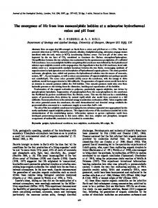
intermediate volumes, one finds bulge shapes (bu*) with long ‘sleeves’ along the γ stripe. These shapes are stabilized by the constraint of constant membrane area and are absent for liquid droplets. Surprisingly, the effective contact angle of the shapes (bu*) increases as the vesicle is deflated. Finally, for small volumes, one has channel shapes (ch) which are approximately described by (3.39) and (3.40) and which are very similar to the corresponding liquid channels. For these channel states, the effective contact angle θeff,γ decreases again as the volume is further decreased. The shape evolution just described applies to all deflation trajectories displayed in figure 3. For larger membrane areas Ame , the deflation trajectories seem to involve a morphological transition which is, however, rather weak since the free energy differences are rather small.
Droplets, bubbles, and vesicles at chemically structured surfaces
(a)
(b)
6s
S557
0s
16 s
3s
35 s
Figure 5. Giant vesicle which adheres to two striped surface domains which represent the γ domains. (a) The two surface domains without the vesicle. Each γ stripe has a length of 50 µm and a width of 5 µm; the separation of the two stripes is 5 µm as well. (b) The free vesicle after release from the micropipette. The remaining five images show the time evolution of the vesicle shape between 0 and 35 s as the vesicle spreads over the two striped domains.
Adhesion experiments. In this last subsection, we will report preliminary experimental observations on vesicles which strongly adhere to a chemically structured glass surface. The γ domains are prepared by vapour deposition of chromium and gold through a custom made grid. The final thickness of these surface domains is about 25 nm as confirmed by atomic force microscopy and their lateral size varies from a few microns up to many tens of microns. A self-assembled monolayer of aminoalkanethiol (HS(CH)11 NH2 ) is formed on these γ domains which then become positively charged in aqueous solution while the noncoated glass surface is negatively charged. Negatively charged vesicles in contact with these structured glass surfaces are attracted towards the positively charged γ domains and repelled from the negatively charged δ domains. These vesicles are prepared from a mixture of DOPC:DOPG (9:1) by the method of electroformation in sucrose solution and subsequently diluted in isotonic glucose solution. The adhering vesicles are observed by phase contrast microscopy. An example of such a vesicle is shown in figure 5. In this case, a giant vesicle, which is essentially spherical with a diameter of about 32 µm, is aspirated by a micropipette and brought into contact with two striped γ domains. Inspection of figure 5 clearly shows that the vesicle adapts its shape in order to spread over these domains. Similar observations were also made in [63]. What remains to be done in order to probe the shape evolution of the adhering vesicle as predicted above is to deflate them in a controlled manner. Acknowledgment This work was supported by the Deutsche Forschungsgemeinschaft through the Schwerpunktprogramm 1052. References [1] [2] [3] [4]
Lenz P and Lipowsky R 1998 Phys. Rev. Lett. 80 1920 Gau H, Herminghaus S, Lenz P and Lipowsky R 1999 Science 283 46 Brinkmann M and Lipowsky R 2002 J. Appl. Phys. 92 4296 Silver J, Mi Z H, Takamoto K, Bungay P, Brown J and Powell A 1999 J. Colloid Interface Sci. 219 81
S558 [5] [6] [7] [8] [9] [10] [11] [12] [13] [14] [15] [16] [17] [18] [19] [20] [21] [22] [23] [24] [25] [26] [27] [28] [29] [30] [31] [32] [33] [34] [35] [36] [37] [38] [39] [40] [41] [42] [43] [44] [45] [46] [47] [48] [49] [50] [51] [52] [53] [54] [55] [56] [57] [58] [59] [60] [61] [62] [63]
R Lipowsky et al Lenz P, Fenzl W and Lipowsky R 2001 Europhys. Lett. 53 618 Gleiche M, Chi L and Fuchs H 2000 Nature 403 173 Lenz P, Bechinger C, Sch¨afle C, Leiderer P and Lipowsky R 2001 Langmuir 17 7814 Sch¨afle C, Brinkmann M, Bechinger C, Leiderer P and Lipowsky R 2004 in preparation L´eopoldes J, Dupuis A, Bucknall D and Yeomans J 2003 Langmuir 19 9818 Feng L et al 2003 Angew. Chem. Int. Edn 42 4217 Lipowsky R, Lenz P and Swain P 2000 Colloid Surf. A 161 3 Lipowsky R 2001 Interface Sci. 9 105 Pesheva N and Oshanin G 2002 Colloid Surf. A 206 349 Kargupta K and Sharma A 2002 Langmuir 18 1893 Thiele U, Brusch L, Bestehorn M and B¨ar M 2003 Eur. Phys. J. E 11 255 Warner M, Craster R and Matar O 2003 J. Colloid Interface Sci. 267 92 Valencia A and Lipowsky R 2004 Langmuir 20 1986 Swain P and Lipowsky R 2000 Europhys. Lett. 49 203 Valencia A, Brinkmann M and Lipowsky R 2001 Langmuir 17 3390 Overduin S and Patey G 2003 J. Chem. Phys. 119 8676 Swain P and Lipowsky R 1998 Langmuir 14 6772 Jakubczyk P and Napi´orkowski M 2002 Phys. Rev. E 66 041107 Henderson J 2004 J. Chem. Phys. 120 1535 Seemann R, Brinkmann M, Kramer E J, Lange F F and Lipowsky R 2004 Proc. Natl Acad. Sci. USA submitted Qu´er´e D 2002 Physica A 313 32 Geoghegan M and Krausch G 2003 Prog. Polym. Sci. 28 261 Blossey R 2003 Nat. Mater. 2 301 Pfohl T, Mugele F, Seemann R and Herminghaus S 2003 Chem. Phys. Chem. 4 1291 Wente H 1971 Math. Z. 120 277 Steffen K 1986 Arch. Ration. Mech. Anal. 94 101 Struwe M 1988 Plateau’s Problem and the Calculus of Variations (Princeton, NJ: Princeton University Press) Sullivan J and Morgan F 1996 Int. J. Math. 7 833 Struwe M 1996 Variational Methods (Berlin: Springer) Buehrle J, Herminghaus S and Mugele F 2003 Langmuir 18 9771 Iliev S and Pesheva N 2003 Langmuir 19 9923 Lipowsky R 2001 Curr. Opin. Colloid Interface Sci. 6 40 Darhuber A, Trojan S, Miller S and Wagner S 2000 J. Appl. Phys. 87 7768 Schneemilch M, Quirke N and Henderson J 2003 J. Chem. Phys. 118 816 Klingner A and Mugele F 2004 J. Appl. Phys. 95 2918 Rowlinson J and Widom B 1982 Molecular Theory of Capillarity (Oxford: Clarendon) Rosso R, Verani M and Virga E 2003 J. Phys. A: Math. Gen. 36 12475 Brinkmann M, Kierfeld J and Lipowsky R 2004 J. Phys. A: Math. Gen. 37 11547 Gretz R D 1966 J. Chem. Phys. 45 3160 Boruvka L and Neumann A 1977 J. Chem. Phys. 66 5464 Rusanov A I 1977 Colloid J. USSR 39 618 (Engl. Transl.) Marmur A 1998 Colloids Surf. A 136 81 Canham P 1970 J. Theor. Biol. 26 61 Helfrich W 1973 Z. Naturf. c 28 693 Seifert U, Berndl K and Lipowsky R 1991 Phys. Rev. A 44 1182 Evans E and Yeung A 1994 Chem. Phys. Lipids 73 39 Bukman D, Yao J and Wortis M 1996 Phys. Rev. E 54 5463 Ou-Yang Z-C and Helfrich W 1989 Phys. Rev. A 39 5280 Powers T, Huber G and Goldstein R 2002 Phys. Rev. E 65 041901 Seifert U and Lipowsky R 1990 Phys. Rev. A 42 4768 Smith A-S, Sackmann E and Seifert U 2003 Europhys. Lett. 64 281 Evans E 1980 Biophys. J. 31 425 Lipowsky R 1995 Structure and Dynamics of Membranes (Handbook of Biological Physics) vol 1 ed R Lipowsky and E Sackmann (Amsterdam: Elsevier) pp 521–602 Blokhuis E and Sager W F C 1999 J. Chem. Phys. 111 7062 Lipowsky R and Seifert U 1991 Mol. Cryst. Liq. Cryst. 202 17 Karlsson A, Karlsson R, Karlsson M, Cans A-S, Str¨onberg A, Rytts´en F and Orwar O 2001 Nature 409 150 Smith A-S, Sackmann E and Seifert U 2004 Phys. Rev. Lett. 92 208101 Lipowsky R and Dimova R 2003 J. Phys.: Condens. Matter 15 S31 Bernard A-L et al 2000 Langmuir 16 6801