IEEE TRANSACTIONS ON ANTENNAS AND PROPAGATION, VOL. 58, NO. 3, MARCH 2010
817
Dual-Grid Finite-Difference Frequency-Domain Method for Modeling Chiral Medium Erdogan Alkan, Member, IEEE, Veysel Demir, Member, IEEE, Atef Z. Elsherbeni, Fellow, IEEE, and Ercument Arvas, Fellow, IEEE
Abstract—A dual-grid finite-difference frequency-domain (DG-FDFD) method is introduced to solve for scattering of electromagnetic waves from bianisotropic objects. The formulations are based on a dual-grid scheme in which a traditional Yee grid and a transverse Yee grid are combined to achieve coupling of electric and magnetic fields that is imposed by the bianisotropy. Thus the underlying grid naturally supports the presented formulations. Introduction of a dual-grid scheme doubles the number of electromagnetic field components to be solved, which in turn implies increased time and memory of the computational resources for solution of the resulting matrix equation. As a remedy to this problem, an efficient iterative solution technique is presented that effectively reduces the solution time and memory. The presented formulations can solve problems including bianisotropic objects. The validity of the formulations is verified by calculating bistatic radar cross-sections of three-dimensional chiral objects. The results are compared with those obtained from analytical and other numerical solutions. Index Terms—Chiral media, electromagnetic scattering, finite difference methods, iterative methods.
I. INTRODUCTION
T
HE analysis of chiral materials has been an important topic in computational electromagnetics especially after artificial chiral materials have been manufactured in the microwave range in the last decade. Numerical analysis of chiral materials has been carried out using a variety of numerical methods, such as the method of moments (MoM) [1]–[4], the finite-difference time-domain (FDTD) method [5]–[11], finite-difference frequency-domain (FDFD) method [12], generalized multipole technique (GMT) method [13], surface integral equation method (SIEM) [14], and hybrid finite element method (FEM) [15]. Every one of these methods has its own unique strengths and weaknesses, depending on the problem considered. One of the strengths of FDFD scheme is that it has no analytical load, such Manuscript received January 21, 2009; revised August 16, 2009. First published December 28, 2009; current version published March 03, 2010. E. Alkan was with the Department of Electrical Engineering and Computer Science, Syracuse University, Syracuse, NY 13244 USA. He is now with PPC Syracuse, East Syracuse, NY 13057-4010 USA (e-mail:
[email protected];
[email protected]). E. Arvas is with the Department of Electrical Engineering and Computer Science, Syracuse University, Syracuse, NY 13244 USA (e-mail:
[email protected]). V. Demir is with the Department of Electrical Engineering, Northern Illinois University, DeKalb, IL 60115 USA (e-mail:
[email protected]). A. Z. Elsherbeni is with the Department of Electrical Engineering, The University of Mississippi, University, MS 38677 USA (e-mail:
[email protected]). Digital Object Identifier 10.1109/TAP.2009.2039297
as derivation of structure dependent Green’s functions, and thus it is easy to understand and implement. Furthermore, it is easy to model complex materials such as inhomogeneous, anisotropic, or dispersive materials. Therefore, FDFD can simulate structures with no known analytical solution. The technique is also very robust and does not suffer from stability problems often encountered in time domain methods such as FDTD [16]. Despite these advantages, the memory required by FDFD method is very high and it requires multiple runs to obtain the broadband response of a given problem. For example, FDTD supplies a very broadband data with a single simulation run with much less memory requirements. In [12], the classical Yee [17] cells are used to compose the computational space. On the traditional Yee grid the electric field components and magnetic field components are not located at the same spatial positions. On the other hand, the electric and magnetic field components in chiral media are coupled by the chirality parameter. This coupling requires that the electric and magnetic field components are positioned at the same node. This problem is overcome in [12] by averaging the known field components for the field positions where they are needed. An alternative method, in which two transverse Yee grids are overlapping so that the same components of electric and magnetic fields coexist at the same locations, is proposed in [7] and [8] to solve one-, two-, and three-dimensional problems using FDTD method. Three-dimensional FDTD formulations employing this dual-grid scheme are presented in [11]. The FDFD method, on the other hand, has not yet benefited from the advantages of this approach. No results are published for one-, two- and three-dimensional scattering problems. In this paper, the general 3D frequency domain numerical method based on dual-grid (DG-FDFD) approach has been formulated for general bianisotropic materials and results for chiral objects—a subclass of bianisotropic materials—are presented. In order to show the validity of the derived formulations, bi-static radar cross-sections (RCS) of arbitrary shaped objects have been obtained and the results are compared to exact solution and other numerical solutions. As a drawback, the introduction of a dual-grid scheme doubles the number of electromagnetic field components to be solved, which in turn implies increased time and memory in solution of the resulting matrix equation. As a remedy to this problem, an efficient iterative solution algorithm is developed. The new algorithm effectively reduces the time and memory requirements, thus compensates for the implied overhead.
0018-926X/$26.00 © 2010 IEEE
818
IEEE TRANSACTIONS ON ANTENNAS AND PROPAGATION, VOL. 58, NO. 3, MARCH 2010
II. SCATTERED FIELD FORMULATION The presented method is based on the scattered field formulation, such that (1) (2) and are total fields, scattered fields are where denoted by and , whereas the incident fields are denoted and . “a” and “b” represents the index numbers by of the field components on the first grid and the second grid, respecitively. Using the bi-isotropic constitutive relations in Maxwell’s equations in frequency domain and using the relations in (1) and (2) for the total fields, one can obtain (3) (4)
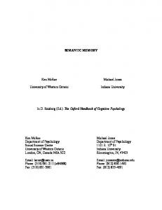
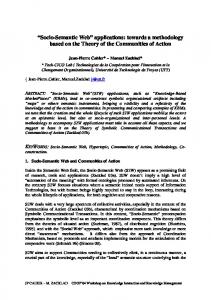
Fig. 1. The field components on the modified Yee cell for DG-FDFD method.
TABLE I ACTUAL SPATIAL LOCATIONS OF THE FIELD COMPONENTS
where (5) (6) Here, is permittivity, is permeability, the measure of nonreciprocity, and is the measure of chirality of the material. As can be seen from (3) and (4), the electric and magnetic field components are coupled by means of and parameters. This coupling requires the coexistence of the same-polarized components of electric and magnetic fields at the same spatial poand , and , and and . However, sitions, i.e. on a traditional Yee grid same-polarized field components are not defined at the same positions. The chiral FDFD formulation presented in [12] is based on the traditional Yee grid and this problem is overcome by averaging the field components for the positions where they are needed. The dual-grid approach employs two Yee grids: one traditional Yee grid, and the other a transverse Yee grid in which the electric and magnetic field positions are swapped. Dual-grid is the combination of these two grids such that same-polarized components of electric and magnetic fields coexist at the same spatial positions. The approach is named as dual-grid finite-difference frequency-domain (DG-FDFD) method for this reason. In this case, there is no need to perform averaging during the calculations as in [12], and formulation is more compatible with the underlying spatial discretization. The spatial positions of the field components on the modified Yee cell used for dual-grid approach are shown in Fig. 1. Additionally, actual index numbers of the field components are depicted in Table I. Decomposing the vector equations in (3) and (4) in Cartesian coordinates for both defined grids, representing the space derivatives by central-difference approximations and modifying the equations to model the absorbing boundaries as PML layers with the notations being used in [18], one can obtain the following for the -components.
For the first grid
(7)
(8) where in the non-PML region (9)
ALKAN et al.: DG-FDFD METHOD FOR MODELING CHIRAL MEDIUM
819
and in the PML region
(10) For the second grid
cell and 2 grids, the total number of scattered field components, . The coefficients thus the number of unknowns in (15) is is a non-singular, highly sparse large matrix. Using matrix direct solution methods solving large sparse matrices, such as Gaussian elimination, Cramer’s rule and inverse matrix method, is very costly in terms of memory and CPU time. Therefore an iterative method is preferred to solve sparse linear set of equations to save time and memory. Results in this paper are obtained based on the iterative method called improved “vanilla” BiCGStab(l) iterative method written by Botchev based on [19]. The BiCGStab (bi-conjugate gradient stabilized) method has been introduced in [20]. The method is enhanced in [21]–[23]. BiCGStab algorithm starts with an initial solution vector . As the iterations proceed, the solution vector converges to the actual solution. The iteration is terminated when the relative error of the solution is less than a given tolerance. IV. TIME AND MEMORY REQUIREMENTS
(11)
(12) where in the non-PML region (13) and in the PML region
The amount of memory required for the solution of a sparse matrix equation is mainly determined by the size of the coefficients matrix—the number of non-zero coefficients. Examining one of the equations, for instance (7), one can verify that there . Thus the number of are 6 non-zero coefficients in a row of , and number of non-zero coefficients in unknowns is is for the DG-FDFD method. The FDFD method in [12], solves for 6 field components per . The number of cell, thus the number of unknowns is non-zero coefficients in a row of coefficients matrix is 13, which as makes the total number of non-zero coefficients in for the FDFD method. Basically, there is no significant difference between the memory requirements of DG-FDFD and FDFD. However, when the problem given in Fig. 2 is run using DG-FDFD and FDFD, a significant difference has been observed between the solution times of these two methods; the simulation takes approximately 312 minutes for the DG-FDFD method, and 210 minutes for the FDFD method. The following section discusses the enhancement of the solution algorithm to improve the computation time of the DG-FDFD method. V. DG-FDFD METHOD WITH IMPROVED SOLUTION ALGORITHM
(14)
III. SOLUTION OF THE DERIVED EQUATIONS After all the equations are obtained for both grids, and for , , and components, they are combined to form a matrix equation for a computation space composed of cells as (15) where is the coefficients matrix, is the unknown vector containing scattered electric and magnetic field components of is the excitation vector, due to incident field, repboth grids, resenting the right hand sides of (7), (8), (11), (12), and the rest of the derived equations. Since there are 6 field components per
As discussed in the previous section, although DG-FDFD requires less memory, it is inefficient in the solution time. One unknowns, while this can notice that FDFD solves for number is for DG-FDFD. Following is an algorithm that reduces the number of unknowns for DG-FDFD and reduces the simulation time. The BiCGStab algorithm requires the computation of the right-hand side of the matrix equation for a given solution at every time step. The algorithm then uses this vector temporary right-hand side internally to check for the conver. gence of the solution and generate a new solution vector For the DG-FDFD, the temporary right hand side is calculated by due to (15). As the number of by multiplying unknowns increase, the solution of matrix-vector multiplications in BiCGStab takes longer times, resulting in longer total simulation times as it is observed from initial experiment.
820
IEEE TRANSACTIONS ON ANTENNAS AND PROPAGATION, VOL. 58, NO. 3, MARCH 2010
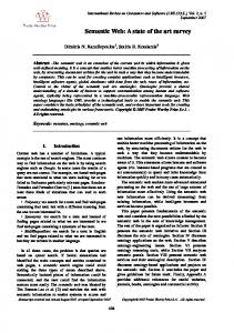
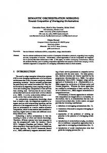
Therefore, in order to increase the method efficiency, number of unknowns should be reduced. Actually, the equations relating the electric and magnetic fields [(7), (8), (11), (12), and other equations] can be put in the following form: (16) (17) Here, the electric and magnetic field vectors are (18a) (18b) Fig. 2. A sketch of the problem setup for the chiral sphere.
and are coefficients matrices and they can be ex. and are excitation vectors and tracted from vector. they are upper half and lower half subsections of Equation (17) can be rearranged as
TABLE II FDFD VERSUS EFFICIENT DG-FDFD
(19) Then electric field vector can be obtained substituting (19) in (16) as
(20) where
is identity matrix. As one can observe from (20), is a new coefficients matrix and is the vector for which the solution is sought. Thus, while solving the matrix equation, we account for only the electric fields; only the electric field components are treated as unknowns. Then the BiCGStab algorithm can be employed to solve (20) rather than (15). It should be noted that a new coefficients matrix is not con; it is found that such a coefstructed for ficients matrix will include 17 nonzero coefficients in each row, thus increasing the memory requirement significantly. Instead, (20) is kept as is and the following described algorithm is employed. The right-hand side of (20) is calculated before calling BiCGStab. Inside the BICGStab at every iteration the temporary right-hand side is calculated in three steps as follows: ; Step 1) ; Step 2) . Step 3) is a temporary vector which stores the result in the Here intermediate steps. and has Each of the new coefficients matrices rows and 5 non-zero coefficients in a row. Thus their . sizes will be VI. RESULTS The computer being used for the simulations has Intel Quad 2.5 GHz processor and 4 GB DDR RAM. The program is written and compiled in 64 bit compatible Intel Fortran v10.1.21.
In this section, first simulation time and memory requirements of the efficient DG-FDFD and the FDFD [12] methods are compared based on an example problem given in Fig. 2. Then, the radar cross-sections of different objects are obtained using the efficient DG-FDFD method and compared to exact and other numerical methods. A. Comparing the Methods The sketch of the problem is given in Fig. 2. The problem space includes a sphere of radius 7.2 cm, which is illuminated by an -polarized -traveling incident plane wave at a frequency of 1 GHz. The relative permittivity of the sphere material is 4, while the chirality is 0.5. The computational space is composed of one million cells (on a single grid), each cell with size of 0.25 cm on a side. For the example problem, DG-FDFD method with improved solution algorithm results in 60 million unknowns (5 nonzero coeffients and 12 field components). The number of operations to calculate the above temporary right-hand side in BiCGStab multiplications and is additions, every time the right-hand side is calculated. For the FDFD method [12], number of operations additions and multiplications, every time the right-hand side is calculated. When DG-FDFD with the improved solution algorithm is run to solve the example problem, the solution time is recorded as 208 minutes, which is a very significant reduction from 312 minutes. With the improved solution algorithm, the solution time of DG-FDFD becomes comparable to that of the FDFD method. The comparison of these two methods is given in Table II.
ALKAN et al.: DG-FDFD METHOD FOR MODELING CHIRAL MEDIUM
821
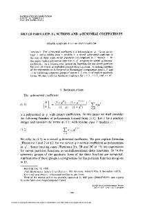
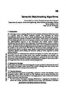
Fig. 3. Co-polarized RCS of the chiral sphere. Fig. 5. A sketch of the problem setup for the chiral cube.
Fig. 4. Cross-polarized RCS of the chiral sphere.
Fig. 6. Co-polarized bistatic RCS of the chiral cube.
B. Scattering from a Chiral Sphere The sphere problem in Fig. 2 is run using the DG-FDFD method and the calculated bistatic radar cross-sections, and , are compared with exact solutions obtained from the program in [24]. The co- and cross-polarized components are plotted in Fig. 3 and Fig. 4, respectively. As observed from these figures, increasing chirality from 0 to 0.5, gave rise to a cross-polarized field, which is the same order as the co-polarized field and that exhibits the optical activity property of the chiral media. Fig. 7. Cross-polarized bistatic RCS of the chiral cube.
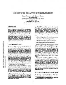
C. Scattering From an Inhomogeneous Chiral Cube A cubic structure is illustrated in Fig. 5. The scatterer is 14 cm long on a side and it has two equal halves separated by the plane. The dielectric constants of both halves are the same as , meanwhile the chirality values are different. The chirality of the left half is zero. The right half has a chirality value . The scatterer is illuminated by an -polarized, of -traveling wave at 0.75 GHz. The computational space is comcubic cells. Each cell has a length of posed of 0.4 cm on a side. The simulation results for co- and cross-polarized radar crosssections of the scatterer are shown in Fig. 6 and Fig. 7, respectively. The results are compared to those obtained using method of moment (MoM) [25] and FDFD method [12]. The DG-FDFD results agree with the MoM and FDFD results.
D. Scattering from a Finite Chiral Cylinder Here, a finite chiral cylinder is simulated. The co-polarized and cross-polarized bistatic radar cross sections of the structure are obtained and compared with the results of MoM, finite-difference time-domain (FDTD) [26] and FDFD method. The computation space is excited by an x-polarized, z-traveling plane wave at 1 GHz. The height of the cylinder is 24 cm and the radius is 12 cm. For this simulation, parameters of the Drude-Born-Fedorov (DBF) constitutive relations are used. The conversions among these parameters are given in [27]. , Namely, the material parameters of the cylinder are and . The converted values are , and . The computation space is divided into
822
IEEE TRANSACTIONS ON ANTENNAS AND PROPAGATION, VOL. 58, NO. 3, MARCH 2010
ponents is much smaller than the magnitude of the co-polarized wave component for the cylinder. VII. CONCLUSION
Fig. 8. A sketch of the problem setup for the chiral cylinder.
In this work, the dual-grid finite-difference frequency-domain (DG-FDFD) scheme for the scattering analysis of three-dimensional objects is proposed. The PML boundary condition and the scattered field approach are successfully implemented into the DG-FDFD formulation. The formulations are based on a dual-grid scheme in which a traditional Yee grid and a transverse Yee grid are combined to achieve coupling of electric and magnetic fields that is imposed by the bianisotropy. Since the coefficent matrix of the method includes all the non-zero coefficients of the electric and magnetic field components, it yields a very long simulation time. For this reason, a more efficient solution algorithm is introduced to increase the simulation speed. Since both electric and magnetic field components are defined at every node on the Yee cell, there is no need to perform averaging as in FDFD method. Therefore, formulation is more compatible with the underlying spatial discretization. In addition to these features, it is shown that, DG-FDFD requires less memory than that of the FDFD, while maintaining comparable simulation time. Finally, the proposed method is validated by analyzing spherical, cubical, and cylindrical chiral scatterers. The results from DG-FDFD are in good agreement with exact, MoM, FDTD, and FDFD results. REFERENCES
Fig. 9. Co-polarized bistatic RCS of the chiral cylinder.
Fig. 10. Cross-polarized bistatic RCS of the chiral cylinder.
cubic cells with 9-cell thick PML layers. The computation space is sketched in Fig. 8. The simulated radar cross-sections of the finite chiral cylinder are given in Fig. 9 and Fig. 10, respectively. As seen from these figures, the obtained results by the DG-FDFD method show a good agreement with the results obtained from other numerical methods. Note that, the magnitude of the cross-polarized com-
[1] F. Altunkilic, “Transmission through an arbitrary aperture in an arbitrary three-dimensional conducting surface enclosing chiral material,” Ph.D. dissertation, Syracuse University, Syracuse, NY, Dec. 2007. [2] M. Hasanovic, C. Mei, J. R. Mautz, and E. Arvas, “Scattering from 3D inhomogeneous chiral bodies of arbitrary shape by the method of moments,” IEEE Trans. Antennas Propag., vol. 55, p. 1817, 2007. [3] D. Worasawate, J. R. Mautz, and E. Arvas, “Electromagnetic scattering from an arbitrarily shaped three-dimensional homogeneous chiral body,” IEEE Trans. Antennas Propag., vol. 51, p. 1077, 2003. [4] M. Yuceer, J. R. Mautz, and E. Arvas, “Method of moments solution for the radar cross section of a chiral body of revolution,” IEEE Trans. Antennas Propag., vol. 53, p. 1163, 2005. [5] M. G. Bray and D. H. Werner, “A simple dispersive Chiral FDTD formulation implemented on a Yee grid,” in Proc. IEEE Antennas Propag. Society Int. Symp. and URSI National Radio Science Meeting, 2005, vol. 1, p. 126. [6] V. Demir, A. Z. Elsherbeni, and E. Arvas, “FDTD formulation for dispersive chiral media using the Z transform method,” IEEE Trans. Antennas Propag., vol. 53, p. 3374, 2005. [7] A. Grande, I. Barba, A. C. L. Cabeceira, J. Represa, P. P. M. So, and W. J. R. Hoefer, “FDTD modeling of transient microwave signals in dispersive and lossy bi-isotropic media,” IEEE Trans. Microw. Theory Tech., vol. 52, p. 773, 2004. [8] A. Grande, I. Barba, A. C. L. Cabeceira, J. Represa, K. Karkkainen, and A. H. Sihvola, “Two-dimensional extension of a novel FDTD technique for modeling dispersive lossy bi-isotropic media using the auxiliary differential equation method,” IEEE Microw. Wireless Compon. Lett., vol. 15, p. 375, 2005. [9] L. D. S. Alcantara, “An unconditionally stable FDTD method for electromagnetic wave propagation analysis in bi-isotropic media,” in Proc. SBMO/IEEE MTT-S Int. Microw. Optoelectron. Conf., 2005, p. 661. [10] A. Akyurtlu and D. H. Werner, “BI-FDTD: A novel finite-difference time-domain formulation for modeling wave propagation in bi-isotropic media,” IEEE Trans. Antennas Propag., vol. 52, p. 416, 2004. [11] M. G. Bray, “Finite-difference time-domain simulation of electromagnetic bandgap and bi-anisotropic metamaterials,” Ph.D. dissertation, The Pennsylvania State University, University Park, Dec. 2005.
ALKAN et al.: DG-FDFD METHOD FOR MODELING CHIRAL MEDIUM
[12] L. Kuzu, V. Demir, A. Z. Elsherbeni, and E. Arvas, “Electromagnetic scattering from arbitrarily shaped chiral objects using the finite difference frequency domain method,” in proc. Progr. Electromagn. Res., PIER, 2007, vol. 67, pp. 1–24. [13] Z. Ming and W. X. Zhang, “Scattering of electromagnetic waves from a chiral cylinder of arbitrary cross section-GMT approach,” Microw. Opt. Technol. Lett., vol. 10, p. 22, 1995. [14] A. I. Fedorenko, “Solution of the problem of electromagnetic wave scattering by a homogeneous chiral cylinder using the surface integral equation method,” J. Commun. Technol. Electron., vol. 40, p. 134, 1995. [15] Y. J. Zhang and E. P. Li, “Scattering of three-dimensional chiral objects above a perfect conducting plane by hybrid finite element method,” J. Electromagn. Waves Applicat., vol. 19, p. 1535, 2005. [16] M. Gokten, “New frequency domain electromagnetic solvers based on multiresolution analysis,” Ph.D. Dissertation, Syracuse Univ., Syracuse, NY, Dec. 2007. [17] K. S. Yee, “Numerical solution of initial boundary value problems involving Maxwell’s equations in isotropic media,” IEEE Trans. Antennas Propag., vol. 14, p. 302, 1966. [18] M. Al Sharkawy, V. Demir, and A. Z. Elsherbeni, “Iterative multiregion technique for large-scale electromagnetic scattering problems: Twodimensional case,” Radio Sci, vol. 40, Sep. 2005. [19] D. R. Fokkema, Enhanced Implementation of BiCGStab (l) for Solving Linear Systems of Equations Preprint 976, Dept. Math., Utrecht University, The Netherlands. [20] H. A. Van der Vorst, “Bi-CGSTAB: A fast and smoothly converging variant of Bi-CG for the solution of nonsymmetric linear systems,” SIAM J. Sci. Stat. Comput., vol. 13, pp. 631–644, 1992. [21] G. L. G. Sleijpen and D. R. Fokkema, “BiCGstab(l) for linear equations involving unsymmetric matrices with complex spectrum,” Electron. Trans. Numer. Analy. (ETNA), vol. 1, pp. 11–32, 1993. [22] G. L. G. Sleijpen and H. A. van der Vorst, “Maintaining convergence properties of BiCGstab methods in finite precision arithmetic,” Numer. Algorithms, vol. 10, p. 203, 1995. [23] G. L. G. Sleijpen and H. A. van der Vorst, “Reliable updated residuals in hybrid Bi-CG methods,” Computing, vol. 56, p. 141, 1996. [24] V. Demir, A. Elsherbeni, D. Worasawate, and E. Arvas, “A graphical user interface (GUI) for plane-wave scattering from a conducting, dielectric, or chiral sphere,” IEEE Antennas Propag. Mag., vol. 46, p. 94, 2004. [25] M. Hasanovic, “Electromagnetic scattering from an arbitrarily shaped three-dimensional inhomogeneous chiral body,” Ph.D. dissertation, Syracuse University, Syracuse, NY, May 2006. [26] V. Demir, “Electromagnetic scattering from three-dimensional chiral objects using the FDTD method,” Ph.D. Dissertation, Syracuse Univ., Syracuse, NY, Jun. 2004. [27] I. V. Lindell, A. H. Sihvola, S. A. Tretyakov, and A. J. Viitanen, Electromagnetic Waves in Chiral and Bi-Isotropic Media. Boston, MA: Artech House, 1994.
Erdogan Alkan (M’08) was born in Nigde, Turkey, in 1978. He received the B.S.E.E. and Ph.D. degrees from Syracuse University, Syracuse, NY, in 2003 and 2009, respectively. He was a Research Assistant at Syracuse University, from 2001 to 2005, where he worked on LNAs, high power amplifiers, pulse circuits, and RF and microwave passive circuits such as filters, and couplers. His research interests are in electromagnetic scattering and finite difference frequency domain method. He is currently working at PPC, Syracuse, NY, as an RF Design Engineer.
823
Veysel Demir (S’00–M’05) was born in Batman, Turkey, in 1974. He received the B.S.E.E. degree from Middle East Technical University, Ankara, Turkey, in 1997 and the M.S.E.E. and Ph.D. degrees from Syracuse University, Syracuse, NY, in 2002 and 2004, respectively. He was with Sonnet Software, Inc., Liverpool, NY, from 2000 to 2004. He worked as Visiting Research Scholar at the Electrical Engineering Department, University of Mississippi, University, from 2004 to 2007. He is now with the Department of Electrical Engineering, Northern Illionis University, Dekalb, working as an Assistant Professor. His research interests include computational electromagnetics, numerical techniques such as FDTD, FDFD, MoM, RF and microwave circuits, and antenna design.
Atef Z. Elsherbeni (S’84–M’86–SM’91–F’07) is a Professor of electrical engineering, Associate Dean for Research and Graduate programs, Director of The School of Engineering CAD Lab, and the Associate Director of The Center for Applied Electromagnetic Systems Research (CAESR), The University of Mississippi, University. He is also an adjunct Professor in the Department of Electrical Engineering and Computer Science, L.C. Smith College of Engineering and Computer Science, Syracuse University. He has conducted research dealing with scattering and diffraction by dielectric and metal objects, finite difference time domain analysis of passive and active microwave devices including planar transmission lines, field visualization and software development for EM education, interactions of electromagnetic waves with human body, sensors development for monitoring soil moisture, airports noise levels, air quality including haze and humidity, reflector and printed antennas and antenna arrays for radars, UAV, and personal communication systems, antennas for wideband applications, and antenna and material properties measurements. He is the coauthor of the following books The Finite Difference Time Domain Method for Electromagnetics With MATLAB Simulations (Scitech 2009), Antenna Design and Visualization Using Matlab (Scitech, 2006), MATLAB Simulations for Radar Systems Design (CRC Press, 2003), Electromagnetic Scattering Using the Iterative Multiregion Technique (Morgan & Claypool, 2007), and Electromagnetics and Antenna Optimization using Taguchi’s Method (Morgan & Claypool, 2007). He is the main author of the chapters “Handheld Antennas” and “The Finite Difference Time Domain Technique for Microstrip Antennas” in the Handbook of Antennas in Wireless Communications (CRC Press, 2001). Dr. Elsherbeni is a Fellow of the Institute of Electrical and Electronics Engineers (IEEE) and a Fellow of the Applied Computational Electromagnetic Society (ACES). He is the Editor-in-Chief of the ACES Journal and an Associate Editor of the Radio Science Journal.
Ercument Arvas (M’85–SM’89–F’03) received the B.S. and M.S. degrees from the Middle East Technical University, Ankara, Turkey, in 1976 and 1979, respectively, and the Ph.D. degree from Syracuse University, Syracuse, NY, in 1983, all in electrical engineering. From 1984 to 1987, he was with the Electrical Engineering Department, Rochester Institute of Technology, Rochester, NY. In 1987, he joined the Electrical Engineering and Computer Science Department, Syracuse University, where he is currently a Professor in the Electrical Engineering and Computer Science Department. His research and teaching interests are in electromagnetic scattering and microwave devices. Prof. Arvas is a Member of the Applied Computational Electromagnetics Society (ACES).