DUNE-A multilayer gridless routing system - Computer-Aided Design
Recommend Documents
resented by a corner-stitching data structure [13], as shown in Figure 2(c). ..... congested tiles which are assigned with higher penalties. In- stead of finding ...
Via Design Rule Consideration in Multilayer Maze. Routing Algorithms. Jason Cong, Jie Fang, and Kei-Yong Khoo. AbstractâMaze routing algorithms are ...
Absfract-The printed circuit boards (PCB's) for the 1990's ... straints, complex packaging and manufacturing technology, .... grids in complex multilayer PCB's.
gaming. – H igh-bay areas. – Retail space. Libretto™ Gridless. Metal Ceiling
System. Features and Benefits. – Collaborate with USG to create a custom
design.
Conference of PHySIcS of NonequIlIbrIuM AToMIc SySTeMS And CoMpoSITeS, PNASC 2015, 18Y20 ... TWo MAIn pHySIcAl probleMS In lASer MASS SpecTroMeTry Are HIgH ... To Solve THeSe probleMS, reSeArcHerS Are creATIng A long free plASMA drIfT gAp And TryIng
Eiji Oki, Kohei Shiomoto, and Daisaku Shimazaki, NTT Network Service Systems .... The structure of a photonic MPLS router with multilayer traffic engineering.
Regulation. Figure 1 Process of piping system design. Because the piping design process requires a variety ... routing within an industrial plant uses the Lee Maze algorithm .... Designer module which considers the layout of cargo holds, pipe ...
The advent of real-time multimedia services over the Internet has stimulated new .... S. O. F. Idzikowski, C. Raack, H. Woesner, A. Wolisz, "Dynamic routing at ...
ent layers: synchronous optical network. (SONET) and optical wavelength-division multi- plexing (WDM). When the photonic MPLS router network is considered, ...
defined by the International Telecommunication. Union â Telecommunication Standardization. Sector (ITU-T) [2]. ASON provides dynamic setup of optical ...
2005 considered the response simulation for a rail-track-sleeper- ground system under train passage. However, most of the meth- ods proposed suffer from ...
WIRELESS COMMUNICATIONS / WLAN APPLICATIONS. A Thesis ..... Microstrip
antennas have received much consideration for implementation in system-on-.
where fep and fmp are the electric and magnetic plasma frequencies, fm0 is the magnetic ..... Smith, D. R., W. J. Padilla, D. C. Vier, S. C. Nemat-Nasser,.
Cuenca, Ecuador. Xavier Franch. Universitat Politècnica de Catalunya. Barcelona, Spain. RE'11, Trento (Italy) â August, 2011. Requirements Negotiation for.
LTCC technology is compatible with the flip-chip technique. The low Temperature Cofired Ceramic technique was developed around 30 years ago. The method ...
Feb 9, 2005 - A dual time method for solving the two dimensional Euler equations in ... are commonly used to speed up steady flow calculations, to be used w .... keeping the fanshaped angles equivalent ( show n in ... thepoint is on the boundary, fou
Multilayer Switching. ▻CCNP 3 v5 - Chapter 4. Implementing Inter-VLAN
Routing. ▻VLANs. • VLANs are associated with individual networks or
subnetworks.
Sep 4, 2010 - Ion-exchange capacity of zeolites consists in their ability to retain divalent ... 2008; Petrovici & Pacioglu 2010), actual tendency atested by the ..... Tenciu M., Patriche N., TalpeÅ M., Titinschneider V., Gerea D., Savin C., Popa Å
Ion MIrror, THuS TIMe focuSIng WIll geT beTTer, buT fInAl coordInATe ... RiD18450, And THe fInAl reSoluTIon of THe MASS SpecTroMeTer WIll be R D 9600.
KeywordsâEduICR; spoken dialog systems; intelligent call center; voice application. I. INTRODUCTION. In recent years, Vietnamese have been seeing many.
n Resnick paper [9] is shown a foraging model that uses two kinds of pheromones: ants deposit one pheromone to mark trails to the food sources, but a second ...
P2P CDNs do not take into account the routing policy and the economics .... traffic by 45.5% in comparison with the random selection algorithm. Moreover, the ...
4) Output format (FE mesh / IGES wireframe model). 5) Node type to .... geometry is to be converted to a discrete form. This .... ompany_restructuring_plan.html.
DUNE-A multilayer gridless routing system - Computer-Aided Design
for deep submicrometer physical designs. Our detailed routing ..... of such a graph. Wong et al. [29] presented a fairly complete survey on various graphs ...
IEEE TRANSACTIONS ON COMPUTER-AIDED DESIGN OF INTEGRATED CIRCUITS AND SYSTEMS, VOL. 20, NO. 5, MAY 2001
633
DUNE—A Multilayer Gridless Routing System Jason Cong, Fellow, IEEE, Jie Fang, and Kei-Yong Khoo, Member, IEEE
Abstract—Advances of very large scale integration technologies present two challenges for routing problems: 1) the higher integration of transistors due to shrinking of featuring size and 2) the requirement for off-grid routing due to the variable-width variable-spacing design rules imposed by optimization techniques. In this paper, we present a multilayer gridless detailed routing system for deep submicrometer physical designs. Our detailed routing system users a hybrid approach consisting of two parts: 1) an efficient variable-width variable-spacing detailed routing engine and 2) a wire-planning algorithm providing high-level guidance as well as ripup and reroute capabilities. Our gridless routing engine is based on an efficient point-to-point gridless routing algorithm using an implicit representation of a nonuniform grid graph. We proved that such a graph guarantees a gridless connection of the minimum cost in multilayer variable-width and variable-spacing routing problem. A novel data structure using a two-level slit tree plus interval tree in combination of cache structure is developed to support efficient queries into the connection graph. Our experiments show that this data structure is very efficient in memory usage while very fast in answering maze expansion related queries. Our detailed routing system also features a coarse grid-based wire-planning algorithm that uses exact gridless design rules (variable-width and variable-spacing) to accurately estimate the routing resources and distribute nets into routing regions. The wire-planning method also enables efficient ripup and reroute in gridless routing. Unlike previous approaches for gridless routing that explore alternatives of blocked nets by gradually tightening the design rules, our planning-based approach can take the exact gridless rules and resolve the congestion and blockage at a higher level. Our experimental results show that using the wire-planning algorithm in our detailed routing system can improve the routability and also speed up the runtime by 3 to 17 times.
(a)
Index Terms—Deep submicrometer, gridless routing, routing.
I. INTRODUCTION
A
S VERY large scale integration (VLSI) technology reaches deep submicrometer (DSM) dimensions and gigahertz clock frequencies, interconnect has become the dominating factor in determining the performance, power, reliability, and cost of the overall system, as predicted in [1]. Many optimization techniques, including wire sizing (for delay optimization), wire spacing (for delay and noise optimization), etc., have been proposed and shown to be very effective for interconnect optimization [2]. These optimizations Manuscript received November 11, 2000. This work was supported in part by DARPA/ETO under Contract DAAL01-96-K-3600 managed by the U.S. Army Research Laboratory and the National Science Foundation under Grant MIP-9357582. J. Cong and J. Fang are with the Computer Science Department, University of California, Los Angeles, CA 90095 USA (e-mail: [email protected]; [email protected]). K.-Y. Khoo was with the VLSI CAD Laboratory, University of California, Los Angeles, CA 90095 USA. He is now with Verplex Systems Inc., Milpitas, CA 95035 USA (e-mail: [email protected]). Publisher Item Identifier S 0278-0070(01)03084-6.
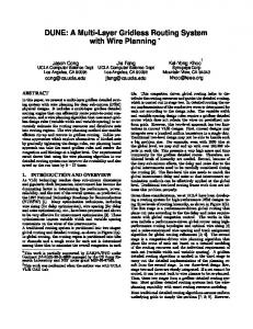
(b) Fig. 1. Routing system design flows. (a) Two-level design flow. (b) Final layout.
impose variable-width and variable-spacing constraints on the interconnects.
IEEE TRANSACTIONS ON COMPUTER-AIDED DESIGN OF INTEGRATED CIRCUITS AND SYSTEMS, VOL. 20, NO. 5, MAY 2001
TABLE I CRITICAL LENGTH l (IN MILLIMETERS) FOR BUFFER INSERTION (BUFFER SIZES RANGE FROM 10 TO 500 MINIMAL GATE SIZE)
TABLE II LOGIC VOLUME ( 10 ) IN NUMBERS OF TWO-INPUT MINIMUM NAND GATES (AREA ESTIMATED BASED ON NTRS’97) THAT CAN BE PACKED IN THE SQUARE AREA OF l =2 l =2
A traditional routing system usually consists of two stages: 1) global routing and 2) detailed routing, as shown in Fig. 1(a). In global routing, the routing region is partitioned into tiles or channels and a rough route for each net is determined among these tiles to minimize the overall congestion in each tile. This congestion-driven global routing helps to distribute the routing resources and guides the detailed routing, which is carried out in stage two. In detailed routing, the exact implementation of the conductive wires is determined for each net according to the design rules. The variable-width and variable-spacing design rules require a gridless detailed router that does not constrain the wires on predefined uniform grids. However, this two-level approach has two limitations in current VLSI designs. First, current designs may integrate over a hundred million transistors in a single chip. Traditional two-level design may not be able to handle such a large size problem. For example, even with 1000 tiles at the global level, we may still end up with over 100 000 objects in each tile. This presents a very high space and time complexity for the gridless detailed router. Therefore, additional levels of hierarchy are needed. Second, and more importantly, because of DSM effects, the delay and noise due to the global interconnects need to be carefully considered during the routing [3]. The first-level tile size needs to match the so-called critical length of global interconnects [4], [5] so that interconnect optimization methods can be effectively applied at the global level. The “critical length” is defined as the minimum wire length beyond which buffer insertion will help to reduce interconnect delay [6]. Table I shows the critical lengths computed in [6] for several future technologies predicted by [1]. Please note that although the minimum distance is decreasing as the feature size scales down, the number of logic cells that can be packed into the region actually increases due to the smaller cell size. If we set the tile dimension to be the critical length (or a fraction of it), the total number of gates1 that can be packed in the region, a so-called logic volume, is shown in Table II, as computed in [6]. This implies that the performance-driven global routing algorithm will generate routing tiles that contain a very large number of objects in each tile. It is up to the detailed router to handle this large number of objects as well as the variable-width and variable-spacing constraints on the interconnects due to the optimization techniques [2]. Therefore, the traditional two-level routing framework does not scale well in DSM designs. Given these considerations, we have been developing a routing system for high-performance DSM designs using three
levels of routing hierarchy, as shown in Fig. 1(b). The first stage is a performance-driven global routing that plans out nets according to the delay and noise requirements with global congestion control. Research in this area includes a performance-driven global router using high-performance routing topologies and optimal wire sizing [7] and a noise-constrained wire spacing and track assignment algorithm for global routing refinement [8], [9]. The second stage is a congestion-driven coarse grid-based wire-planning algorithm that plans the route of each net based on a detailed modeling of the routing resources and the individual requirement of each net (variable-width and variable-spacing). A gridless detailed routing algorithm is applied in the third stage to carry out the detailed implementation of the planning result from the second stage. In our three-level design flow, stages two and three are closely integrated. If a net cannot be routed, it can be sent back to the wire planner to be replanned. Thus, these two stages together form a gridless detailed routing system. Most gridless detailed routing systems lack the wire-planning capability with exact routing resource modeling. Most traditional detailed routing algorithms assume uniform underlying grids to simplify the problem [10]–[12]. However, this uniform-grid approach is not efficient to handle variable-width and variable-spacing designs because a very fine grid may be needed, as shown in Fig. 2(b). Due to the requirement of off-grid routing induced by variable-width and variable-spacing design rules, several gridless detailed routing algorithms have been published during the past years. In general, there are two types of approaches to the gridless routing problem. One approach uses the tile-based algorithms [13]–[15]. The routing region is partitioned into tiles induced by the boundaries of obstacles and the routing problem is reduced to searching a tile-to-tile path among these tiles, represented by a corner-stitching data structure [16], as shown in Fig. 2(c). The other approach uses the connection graph-based algorithm [17]. A connection graph is built based on the obstacles in the routing region and usually the special width and spacing requirements for the net to be routed are encoded in the graph. A maze searching algorithm is applied on the graph to find the route, as shown in Fig. 2(d). In general, searching a tile-to-tile path is faster due to the smaller number of tiles and the use of corner stitching data structure. However, tiles are more complex to manage and a tile-to-tile path needs postprocessing to obtain a final design rule correct route. Moreover, there are some
2
1The
2
gates counted are assumed to be two-input minimum NAND gates.
2
2
CONG et al.: DUNE—A MULTILAYER GRIDLESS ROUTING SYSTEM
635
(a)
(b)
(c)
(d)
Fig. 2. Different approaches for detailed routing. (a) Routing region with obstacle and the design rules. (b) Uniform grid approach that uses very fine grids due to the width and spacing rules. (c) Routing region is cut into tiles according to the obstacle boundaries for a tile-based approach. (d) Connection graph-based approach that is constructed based on the design rules.
difficulties in using the tile-based algorithm for multilayer routing with more complex design rules. When a net cannot be routed in detailed routing, ripup and reroute is carried out to free up routing resources and redo the routing. Many algorithms have been proposed on ripup and reroute strategies [18]–[20]. However, one of the fundamental assumptions they have is that uniform underlying grids are defined and all net segments can be simplified as a zero width lines on these grids. This makes it easy to model the resources in the routing region and simplifies the operation of reroute. However, this assumption does not hold in variable-width and variable-spacing routing. Net segments cannot be simplified to zero width lines and rerouting a net may affect multiple nets in the region. One simple example is shown in Fig. 3. In this case, an accurate model of local resource and the flexibility to select the reroutes globally are both needed to find the solution. We believe that a successful gridless routing system requires not only an efficient multilayer detailed routing algorithm as the routing engine, it also requires a nicely crafted framework that consists of a congestion-driven planning tool that can schedule all the nets together while taking the width and spacing requirements of each net into consideration. It shall have efficient ripup and reroute capabilities when some nets cannot be routed. However, little progress has been reported in this area in the research community. Some solutions have been attempted by the electronic design automation vendors. One of the notable ones is the IC Craftsman from Cooper and Chyan Technology (now part of Cadence). It offers a great deal of flexibility due to its multiple iterations of rerouting, but it may not scale well to future IC designs with hundreds of millions of transistors on a chip.
In this paper, we propose an efficient multilayer variable-width variable-spacing gridless detailed routing system for DSM designs. It features an efficient connection graph-based maze searching algorithm as the gridless routing engine and a wire-planning algorithm as the global planner for the routing engine. Our gridless routing engine uses a nonuniform grid graph as the underlying graph for finding point-to-point connection. We show that this graph is optimal for the multilayer variable-width variable-spacing point-to-point routing problem. We use an implicit representation of the graph. A standard maze-searching algorithm is used to find the connection by constructing the graph on the fly. A slit tree plus interval tree data structure and a cache data structure are invented to support maze related queries. Our congestion-driven wire-planning algorithm not only distributes nets into routing regions prior to detailed routing, but also enables efficient ripup and reroute by replanning nets during the detailed routing. When a net cannot be routed, it is sent back to be replanned by the wire-planning algorithm. This integration of planning and routing algorithms helps the planning algorithm by keeping up-to-date resource information in the routing region and enabling the routing algorithm to change the route globally. In Section II, we present the connection graph-based detailed routing algorithm in our routing system. In Section III, we propose our congestion-driven gridless planning algorithm that effectively plans each net to constrain individual net’s searching space and minimize global congestion. The interaction between the detailed routing algorithm and the planning algorithm that provides an effective ripup and reroute capability is discussed in Section IV. Finally, the effectiveness of our algorithm is
636
IEEE TRANSACTIONS ON COMPUTER-AIDED DESIGN OF INTEGRATED CIRCUITS AND SYSTEMS, VOL. 20, NO. 5, MAY 2001
(a)
(c)
(b)
W
(d)
Fig. 3. Difficulties of ripup and reroute in gridless routing. (a) 3 net is scheduled to be routed through a congested region. (b) Three previously routed nets with 1 , 2 , and 1 width, respectively. It is obvious that ripping up any net will not release enough resources for the new net. Moreover, picking up different nets has different effects. (c) If nets 1 and 2 are removed, there will be extra unusable spaces after routing the new net. (d) The best solution here is to remove nets 1 and 3 and reroute net 2 and the new net.
W W
W
validated with experimental results in Section V. Preliminary results of this paper were presented in [21] and [22].
II. POINT-TO-POINT GRIDLESS ROUTING ENGINE A. Simplified Connection Graph The first problem that we need to address in using the point-to-point approach realizing a gridless router is how to conceptually construct a connection graph on which the maze algorithm can search. A uniform grid graph approach is simple, yet it requires very fine grids (i.e., manufacturing grids). Thus, it is not practical for large gridless routing problems. Many algorithms simplify the connection graph [23]–[26] at the expense of very costly preconstruction and representation. For time example, the track graph [26] requires space for preprocessing, where is total number of and . Therefore, graph edges and in the worst case it could be their usefulness is limited for large designs. Moreover, some of these graphs are not guaranteed to be optimal or are only optimal for single-layer routing problems. To the best of our knowledge, there is little published research work on the multilayer optimal graph. We now introduce a connection graph called nonuniform grid based on the expansion of rectangular obstacles in the graph routing region according to wire/via width and spacing rules. In the routing region, the existing routings and objects are obstacles that current routing path must avoid. These obstacles can be
most conveniently defined as a set of, possibly overlapping, rectangles at different layers . The layout design rules create an obstruction zone [27] around each obstacle where the center lines of wires and center of vias cannot be placed. That is, the center line of a wire of width must be away from the edge of the obstacle at least , where is the wire spacing between the current net and the obstacle . We let be the set of rectangles in that are in each of the four rectilinear directions, as expanded by may not be the minimum shown in Fig. 4. Please note that wire-to-wire spacing and may vary from net to net due to aggressive optimizations in high-performance designs. Similarly, we can create the set of rectangles expanded according to via . Please note that real width and spacing rules, denoted as design rules require minimal metal overlapping over the vias. When we count the via width, we include the metals that overlaps with the via instead of the actual via size. The via spacing must satisfy both the via-to-via distance and the spacing of metal overlapping, as shown in Fig. 5 using the SCMOS design rules from MOSIS [28]. Thus, the following property about via/wire width and spacing design rules is generally true in practice: Property 1: The via width and spacing are always no smaller than the wire width and spacing for the same net on the same layer. Now we can construct two sets of expanded rectangles and according to the wire rules and via rules, respectively. Be, cause of our choosing the expansion value we can see that for any valid multilayer variable-width variable-spacing path, the center line of a wire segment must not
CONG et al.: DUNE—A MULTILAYER GRIDLESS ROUTING SYSTEM
637
(a) (a)
(b) Fig. 4. Obstacle expansion according to width and spacing rules. (a) Without expansion. (b) With expansion, routing path is reduced to zero-width path.
cross the expanded rectangles in while the center of a via must not fall into any rectangles in . Based on these observations, we define our underlying routing graph is defined as follows: Definition 1—Multilayer Variable-Width Variable-Spacing Routing Problem with the Obstacle Set , a Source , and a is an orthogonal grid Sink : A nonuniform grid graph graph in which its grid locations are the vertical boundary plus the locations of and . Similarly, locations of and we can define the grid locations. Any location defined by and grids is a valid graph node if it is not these two 3 as shown in Fig. 6(b). contained2 by any rectangle in or Any graph node is a valid layer-switching point (LSP) between on adjacent layers if it is not contained by any rectangle in the adjacent layers, as shown in Fig. 7. Compared to the uniform grid graph, where current gridless routing may generate very dense grids as shown in Fig. 6(d), our nonuniform grid graph is much sparser. Compared to previous nonuniform graphs, such as the connection graph [25] shown in makes it very easy to come up Fig. 6(c), the gridded nature of with an implicit representation that is both highly compressed in storage and efficient in query, although our graph has more nodes. is a strong connection graph. That is, among Moreover, the shortest paths from to , if any such connection exists among the obstacles with respect to the variable-width vari. We able-spacing design rules, we can at least find one from will show a detailed proof in the following section.
r
p
r
2A point is contained by a rectangle if the point falls within the open rectangle . 3Due to Property 1, in fact we can guarantee that if a point is not contained by any rectangle in ~ , it is not contained by any rectangle in ~ either.
R
R
(b)
M
Fig. 5. SCMOS design rules from MOSIS. (a) Via2, and 3.
M 1, Via, and M 2. (b) M 1,
B. Optimality of Simplified Graph In this section, we prove that the nonuniform grid graph is optimal for multilayer variable-width and variable-spacing routing. To facilitate further discussions, we have the following definitions. Definition 2—Multilayer Point-to-Point Shortest Path (MLSP) Routing Problem: Given a multilayer routing region with rectilinear obstacles and two points, source and destination . Find the shortest rectilinear path from to that follows the wire/via width and spacing rules. The length of a rectilinear path is the sum of the lengths of all its segments. We count the center-line length as the length of a wire segment. The rectilinear distance between two points and equals , where and are the and coordinates of point , respectively. One special case for the multilayer shortest path problem is the zero-width shortest path problem, where the wire/via width and the spacing for the path is zero. This problem has been well studied in computational geometry as well as VLSI computer-aided design due to its applications in the routing problem. One of the key problems is to find an optimal graph—a graph containing at least one of the shortest paths. Wong et al. [26] came up with the concept of the track graph for the singlelayer shortest path problem. However, the track graph they construct does not guarantee to contain the shortest path. Zheng [25] improved the track graph and proposed an optimal connection graph for the single-layer zero-width shortest path problem as well as the implicit representation of such a graph. Wong et al. [29] presented a fairly complete survey on various graphs
638
IEEE TRANSACTIONS ON COMPUTER-AIDED DESIGN OF INTEGRATED CIRCUITS AND SYSTEMS, VOL. 20, NO. 5, MAY 2001
(a)
(b)
(c)
(d)
G
x
Fig. 6. Connection graph generation. (a) Obstacle expansion. Obstacles expanded according to design rules. (b) Nonuniform grid graph. constructed by and locations of ~ , ~ , , and . Here we show the valid graph nodes on one layer. (c) Connection graph. constructed by boundaries and extension lines of ~ and ~ . (d) Uniform grid graph. Uniform grids that use very dense manufacturing grids.
R
y
Fig. 7.
R
RR s
t
Multilayer nonuniform grid graph.
under different optimization functions. However, most of these research works are focused only on single-layer or two-layer routing problems. What is more, none of these works shows results on the optimal graphs for the multilayer variable-width variable-spacing shortest path problem. is optimal for MLSP problem, we To show that our graph can be mapped back first show that any zero-width path on to a valid variable-width variable-spacing path. Because of our based on the wire choosing expansion value and the graph nodes that are not conwidth and spacing tained by any expanded rectangle in , the wire segment cenis wire-rule correct. terlined on any zero-width segment on Similarly, we can show that any via centered on an LSP is via rule correct. Thus, we have the following theorem for mapping
G
a zero-width path on to a variable-width variable-spacing path. , by mapping the Theorem 1: For any zero-width path on segments into the center lines of path segments and the LSPs into the centers of vias, we can get a valid variable-width variable-spacing path. The above theorem only shows one side of the proof that we into a valid multilayer path. can map any zero-width path on is optimal for MLSP problem, we also In order to show that actually need to show that the zero-width shortest path on corresponds to one of the MLSPs in the original set of obstacles . We prove this by showing that there is at least one shortest path among all the MLSPs that the centerlines of the wire seg. In the later part of ments and the center of the vias are on our proof, unless specifically mentioned, the paths we refer to or the center lines are zero-width paths—either the paths on of MLSPs. In our figures, we also simplify the representations of the paths by drawing the center lines only. It is easy to see that for any path from to , we can partition the path into single-layer subpaths plus the vias connecting these paths. By definition, the final cost of the path is the sum of the costs of these subpaths. Lemma 1: Given a multilayer routing problem, any rectilinear path can be decomposed into a sequence of single-layer subpaths and a set of vias that connect them. To show that there is at least one MLSP that the center lines of , we its wire segments and the center of vias are embedded in will show the following. First, among all the shortest paths, there is at least one multilayer path where all the vias along the path . Next, we will show that the center lines of are centered in
CONG et al.: DUNE—A MULTILAYER GRIDLESS ROUTING SYSTEM
(a)
(b)
(c)
(d)
Fig. 8. (a) U-shape path. (b) Z-shape path. (c) Rotation of a path. (d) Special is zero. case:
s
the single-layer subpaths along the MLSP can also be embedded . in To prove that there is at least one MLSP with the centers of its , let us first look closely into the segments vias embedded on that are connected by a via. In general, there are two types of connections, a “U-shape” path and a “Z-shape” path, as shown in Fig. 8(a) and (b), respectively. Other patterns can be derived via rotation or setting some of the segments to zero length, as shown in Fig. 8(c) and (d), respectively. Definition 3—Four-Segment Subpath , , , and Connected by a Via . : Segment and are of the same direction. If and are on the same side with respect to and , it is called a U-shape subpath. Otherwise, it is called a Z-shape subpath. Please note that for a U-shape subpath of MLSP, we can guarantee that either the boundary of wire segment , is at or the boundary of via is at spacing to the boundary of and are the wire spacing and some obstacles, where via spacing specified by the design rules, respectively, as shown in Fig. 9(a). This is because we can otherwise shift , , and upward and reduce the total wire length without violating design rules. Thus, we say that subpath , , and is at minimal spacing to the obstacles. When or is at the minimal spacing to the boundary of the obstacles, then the center line of and is away from the obstacle boundary at direction. When via is at the minimal spacing to the boundary of some away from obstacles, then the center of via is the obstacle boundary at direction. Thus, according to the def, the -coordinate of the via must be on . For inition of a Z-shape subpath, we can shift , and upward or downward until they are at minimal spacing to the boundary of an obstacle. This operation will not change the total wire length of the Z-shape subpath, as shown in Fig. 9(b). According to our analysis of the U-shape subpath, the coordinate of the via center is after the shifting. So there is at least one subembedding on . path of MLSP with the centers of the vias’ -coordinates on
639
(a)
(b)
(c)
(d)
G
Fig. 9. MLSP via embedding on (a) Shifting a U-shape subpath. (b) Shifting a Z-shape subpath. (c) Shifting via so that it is embedded on . (d) Shifting via so that segment is zero.
v
s
v
G
Next, we can shift via along and so that: 1) the center so it is embedded on it, as of via hits one -grid line on shown in Fig. 9(c), or 2) via is at the end of or , as shown , in Fig. 9(d). For the second case, we get a new subpath and . In fact, it can be seen as a special case of path , , , , and in Fig. 8(d), after rotation, where becomes , is zero and becomes in the original path. Thus, our analysis and transformations of -coordinates for U-shape and Z-shape subpaths can be applied to the -coordinates of vias on the new subpath. After repeated application of these transformations, we will be able to shift the vias to locations where their centers are without changing the total wire length of the embedded in MLSP. We have the following lemma. Lemma 2: There is at least one MLSP that the vias along the . path are centered on For any subpaths in the MLSP, according to the optimality property of shortest path, the single-layer subpath must also be a shortest path. What is more, based on our expansion , the single-layer shortest path problem can be translated into finding a zero-width shortest path problem in . In [26], Wong et al. presented a track graph for finding a single-layer rectilinear shortest path. The track graph is constructed by the obstacle boundaries and their extension lines. The track graph is not optimal because in some special cases it and does not contain the shortest path when the two points are located in the same horizontal or vertical regions,4 as shown in Fig. 10(a). An extension of track graph, as proposed by Zheng et al. [25], is to construct the routing graph from the obstacle boundaries and the extension lines that are stopped by these boundaries instead of track lines. The so-called connection graph, as shown in Fig. 10(b), guarantees to embed single-layer shortest paths. By definition, a connection graph , as shown in Fig. 10(c). If a is a subgraph of single-layer 4A horizontal or vertical region is a component of the planar subdivision divided by horizontal or vertical tracks.
640
Fig. 10.
IEEE TRANSACTIONS ON COMPUTER-AIDED DESIGN OF INTEGRATED CIRCUITS AND SYSTEMS, VOL. 20, NO. 5, MAY 2001
shortest path can be embedded into a connection graph, it can . What is more, a straight-forward also be embedded into extension of the single-layer connection graph into a multilayer graph by projecting the graph nodes and edges into all layers does not guarantee to contain the shortest path. The new projected graph even may not contain a path while there are valid point-to-point connections, as shown in Fig. 10(d). Thus, we have the following lemma. Lemma 3: There is at least one set of single-layer subpaths . of MLSP that their center lines are on From Lemmas 1, 2, and 3, we prove the following theorem. Theorem 2: Among the multilayer shortest paths with respect to the obstacles and design rules, there is at least one shortest path that the center lines of its wire segments and the . center of its vias are embedded on Theorem 2 tells us that there is at least one multilayer shortest using its center lines. And from path that can be mapped on can be mapped to Theorem 1, we can see that any path on a valid variable-width variable-spacing path. Thus, the shortest must be the center line of a shortest mulpath we find on tilayer variable-width variable-spacing path. We have the following theorem. is an optimal graph for rectilinear shortest Theorem 3: paths in variable-width variable-spacing multilayer routing. C. Implicit Representation of Connection Graph Instead of precomputing the graph explicitly, we use an implicit representation of the connection graph. We use two sorted and to store the -coordinates and -coordinates, arrays respectively. The advantages of an implicit representation are
that first, it is very efficient in memory representation. The twoarray data structure is linear in terms of the number of obstacles (including existing routes) in the routing region. Second, there is no precomputation of the routing graph. That is, we generate the graph nodes and edges on the fly. The computation of a graph node, a query, consists of two steps: first, compute the possible position of the neighbor, and second, determine the feasibility of a point. Given the position of point and a direction , we need to find the position of the closest neighbor to in the direction quickly in order to support the implicit representation efficiently. Since our connection graph consists of nonuniform grids, we build of sorted -coordinates of the vertical grid lines in . array , the If the -coordinate of the current point corresponds to -coordinate of the neighboring points in the horizontal position or , which can be found in is either time. The preprocessing time to compute such an array requires linear scan of all rectangles and sorting. a We need a similar array for storing -coordinates. So, the data structures to support implicit representation of nonuniform grid connection graphs are simply two arrays with a total memory , where and are the requirement of , respectively. number of horizontal and vertical grid lines in A point is feasible for placing a wire or via if it is not enclosed . Therefore, by the applicable expanded rectangles in or finding the feasibility of a point requires a point enclosure query into the set of expanded rectangles. Point Enclosure Problem: Given a set of rectangles and a point , return the set of rectangles that contain .
CONG et al.: DUNE—A MULTILAYER GRIDLESS ROUTING SYSTEM
641
We will discuss our data structure to support feasibility computation in the next section. D. Query Data Structure The feasibility check answers a simple question: does a point fall into any expanded rectangle? However, the nature of current gridless routing makes this problem not trivial to solve. First, the data structure needs to represent a fairly large and congested region that contains huge amount of rectangular objects. Second, the rectangular objects need to be expanded according to width and spacing rules. These rules may vary from net to net. So the preprocessing time for the query data structure should not be long. Third, the query is being made many times during the routing. So it must be very fast. The point enclosure problem is well studied in computational geometry and it can be solved using segment trees in time and space [30] or solved using time and priority search [31] trees in space, where is the number of rectangles that enclose the point . These tree-based algorithms, although good at static ) data, suffer from long preprocessing time (at least due to expansion, insertion, and deletion. More practical data structures [32]–[35] have been proposed based on organizing the objects into one-dimensional (1-D) buckets [34], [35], two-dimensional (2-D) buckets [33], or 2-D data-oriented buckets called field blocks [32]. An extensive comparison of the tree-based approach versus the 2-D buckets approach can be found in [33]. In preferred layer routing, the obstacles in a given layer are dominated by long rectangles in the preferred routing direction. This favors the 1-D buckets approach such as the “slit tree” in [34] and [35] that recursively bisects the layer into slices in the preferred direction and rectangles intersecting or overlapping a common slice are managed by a bidirectional linked list. The advantage to apply the slit-tree algorithm is that it requires linear memory space and linear preprocessing time while, in practice, the query is constant time. However, applying the simple 1-D bucketing data structure to the nonuniform grid graph query in gridless routing has a drawback: it slows down when the number of objects is large in each slice. Although by further bisection of each slice we can reduce the number of objects in each slice, the number of “small” objects such as vias and short local wires in each slice cannot be effectively reduced. Therefore, we propose a two-level data structure to solve this problem. The first level is a fixed height “slit tree” and the second level is an auxiliary interval tree [36]. Notice that the interval tree has predetermined uniformly spaced cut lines according to the size of slice. The advantage of the interval tree is that long rectangular objects along the preferred direction in each slice are stored at the highest level of interval node they cut, while short objects that fall in between interval lines are stored at leaf nodes, called cells, as illustrated in Fig. 11. The storage space for such a data structure is still linear while the number of rectangles a query needs to check can be fundamentally reduced by traversing the interval tree nodes top-down. Another advantage of this data structure is that its preprocessing time is still constant in practice. However, using any of the existing query approaches for gridless detailed routing has several drawbacks. First, each rectangle
+
Fig. 11. Slit interval tree. Horizontal slices are cut into cells by vertical intervals. Rectangular obstacles are stored on cut lines of leaf cells. Empty-rectangle E is generated as a results of a query to point v .
may need to be expanded many times because the width and spacing rules may be different between wires and vias, from layer to layer, and net to net. Second, it does not exploit the locality of maze routingqueries. In the following paragraphs, wewill present general techniques to overcome these shortcomings. The first problem is due to the expansion of rectangular objects. The algorithm requires expanding all the rectangles according to wire rule and via rule before checking for point enclosure. This is undesirable when the design rules vary frequently from net to net since each set of design rule requires a new set of expanded rectangles. The result is multiple copies of expanded rectangles (wire rule and via rule) and frequent rebuilding of data structures (design rule changes). To solve this problem, we propose to store unexpanded rectangles in the query data structure. Since the query involves a local search around the area of the query point, we can search for all the rectangles that are for wire feawithin the largest expansion distance ( for via feasibility) to the query point and sibility or expanding these rectangles on the fly. By paying the price of a slightly larger searching area, assuming the difference of width and spacing rules are much smaller than the size of “cells,” we are able to eliminate the need for pre-expanding the rectangles and allow the easy implementation of flexible design rules. Second, the query data structure does not exploit the locality of point enclosure queries due to the point-to-point expansion nature in maze routing. Each query into the data structure, although best optimized for tradeoffs between the storage space and the speed of query, still requires multiple levels of tree traversal and linear scan of each object in the cells. This is a very expensive operation because the query needs to be made repeatedly in maze routing. However, we can improve our query performance by exploiting the locality of the queries using a “cache” data structure, independent of the query data structure. The basic operation of maze routing is to expand node by node. So the nature of its queries has strong locality—the queries propagate from the source node location and each time goes to a neighboring location not far away. We can exploit this locality by recording previous query results in a cache, a small fixed-size vector of rectangles from recent query results. We keep two caches in our implementation: an obstacle cache and a “free” cache. If the query point is not enclosed by a rectangle, then we compute the “empty” rectangle around , shown as in Fig. 11. Notice that computing the largest empty rectangle is a
642
IEEE TRANSACTIONS ON COMPUTER-AIDED DESIGN OF INTEGRATED CIRCUITS AND SYSTEMS, VOL. 20, NO. 5, MAY 2001
(a)
(b)
(c)
(d)
Fig. 12. Planning graph construction and wire planning. (a) The routing is first partitioned into tiles and (b) the weighted capacities of each cell is computed using a line-sweeping algorithm. (c) Wire-planning graph is a gridded graph and each node corresponds to a tile. Capacity of the graph edge is the capacity of each tile. (d) Algorithm finds planning result for each net by searching a minimum weighted path in .
G
-hard problem, therefore, we use a simple heuristic here: at is set to be the same size the beginning, the empty rectangle of the cell(s) containing a query point. The rectangular obstacles in the cell(s) are checked one by one, every time we compute a maximal remaining empty rectangle with respect to current . This evolves enumeration of all possible combiobstacle nations of new empty rectangles according to relative positions and , and it takes time. Since we need to between go through the rectangles to check for overlapping anyhow, we are able to get the empty rectangle with little extra effort. If the query point is enclosed by an expanded rectangle, then the expanded rectangle is added to the obstacle cache. The rectangles in each cache are sorted according to the time they are generated, and when the cache is full, the rectangle with “oldest” time stamp is swapped out. Our experiments show that adding in these two caches gives us an 11 times speed-up on average query time in our routing examples. In this section, we present a gridless routing algorithm based on implicit representation of a nonuniform grid graph. The key idea of implicit representation is that the underlying routing graph is computed on the fly instead of being precomputed and stored. Zheng et al. first applied this idea in their connection graph routing algorithm [25]. However, there are two major differences between Zheng’s approach and our approach. First, these two approaches have different underlying graphs. The graph used in [25] is a single-layer graph constructed from the boundaries and the extension lines of the obstacles. Our graph is a multilayer nonuniform grid graph based on the and locations of the obstacle boundaries. In the single-layer case, our graph is a super graph of the connection graph. For the
G
multilayer shortest path problem, our graph is guaranteed to be optimal. A simple extension of the connection graph into a multilayer graph, as shown in Fig. 10(d), does not guarantee its optimality. Second, due to the differences between these two graphs, the data structures that support graph node queries are different. The two-level binary tree in [25] stores line segments from the obstacle boundaries and their extension lines. In our approach, our “slit internal tree” stores rectangular obstacles directly. III. CONGESTION-DRIVEN WIRE PLANNING To overcome the problems of a net-by-net approach using a maze algorithm, we propose a planning algorithm that has the following three features. First, it spreads out nets to reduce overall congestion and, thus, improves routability. Second, it constrains each net’s searching space into preassigned regions to speed up the runtime. Third, it provides an accurate topology for each net in determining its final route or reroute if needed. We call this algorithm a wire-planning algorithm. The major steps in our wire-planning algorithm are highlighted in Fig. 12. There are two features that make the planning algorithm very useful in a gridless detailed routing environment. First, it uses an accurate model to estimate the routing resource in a multilayer gridless routing environment. It can accommodate different wire widths and spacings for different nets. Details of the resource modeling and planning graph construction are discussed in Section III-A. Second, it uses a multiiteration planning method to overcome the net ordering problem, which is discussed in Section III-B.
CONG et al.: DUNE—A MULTILAYER GRIDLESS ROUTING SYSTEM
643
A. Partitioning of Routing Regions and Modeling of Routing Resources Prior to planning the nets, the routing region is partitioned into tiles. Each tile is of fixed height and width. A three-dimensional (3-D) planning graph is built based on these tiles—each graph node corresponds to a tile and the edges link neighboring tiles, as shown in Fig. 12(c). Each net is planned through these tiles by finding a tile-to-tile path on the planning graph. However, the wire-planning algorithm will not be useful without an accurate estimation of the routing resources in each tile. Due to the gridless nature of our routing problem, we cannot simplify the routing resources as the number of grids or routing tracks. So, we are using the actual dimensions of the obstacles in the tile to compute the routing resources, the capacity , on the tile boundary. As part of the detailed routing flow, our wire-planning algorithm has the advantage of knowing the exact situations in the routing region: prerouted wires and pins. The boundary capacity of a tile is a weighted length of the cut line in between the tiles. Using a line-sweeping algorithm [37], we are able to get the accurate blockage information within each tile. The sweeping algorithm cuts the routing region into horizontal and are (or vertical) empty rectangles, called slices, and the width and depth of a slice , as shown in Fig. 12(b). The tile depth is and the boundary capacity is a weighted sum of empty slide widths along the tile boundary computed by the following formula: (1) The interlayer capacity of a tile, which corresponds to the resources taken by vias, is computed by the sum of the area of all empty slices in the tile. B. Planning of Nets Before detailed routing, each net is planned one by one in the routing region. We use a maze-searching algorithm to find a minimum cost path for each net in . The cost of a path is the sum of the edge costs along the path. Each edge cost is determined by a weighting function based on the total consumption, including resources taken by previous planned nets and the sum of actual wire width and spacing of the planned net, and the edge capacity. Several cost functions, as presented in [7], were tested and a slope function was finally chosen based on the experimental results. After the path is found, the edge consumptions along the tiles it goes through are updated by the sum of width and spacing of the net. Local congestion and net ordering could be a problem in our net-by-net approach. We use a negotiation-based algorithm [20] to plan the nets in multiple iterations to minimize local congestion and to avoid the net ordering problem. After one iteration of planning all the nets, the congestion of each tile is computed. A penalty is assigned to each tile based on the congestion so that during the next iteration of planning, routes can be directed away from these potentially congested tiles, which are assigned higher penalties. Instead of finding a “good” ordering for the nets, a simple heuristic is used to determine the net ordering: those nets that go through more congested regions or
have longer detours are prioritized and will be replanned first in the next iteration. Within each iteration, each net is planned with the updated planning graph based on previous planning results. The planning iteration terminates when certain criteria are met: either the global congestion and each net’s planning result (number of bends and the estimated wire length based on the tiles it is planned through) are optimized or the whole planning process has gone through the number of predetermined iterations. After the planning, we weight the edges of the routing graph to minimize local congestion. In our implementation, we are searching for point-to-point connections on the planning graph. However, the overall planning flow and the underlying graph with the accurate modeling of routing resources can be extended to find tree topologies for multiterminal nets. The topology of each net is determined by the tile-to-tile path. The searching space for the maze-based gridless detailed router is constrained in these preplanned tiles, called allowed regions. This speeds up the searching for a final route in each net. However, if no design-rule-correct connection can be found in the allowed regions, a ripup and replan will take place between wire planning and detailed routing, as presented in Section IV. IV. RIPUP AND REPLANNING A. General Ripup and Reroute Approaches Traditional ripup and reroute algorithms assume uniform underlying grids. In general, there are two classes of ripup and reroute algorithms, depending on the kind of routes that the router is allowed to create: 1) always maintain the correct design rule for all routes; 2) allow routes with temporary design-rule violations. There are some limitations for strictly enforcing design-rule correctness in every step during routing. The result will rely heavily on the ordering of nets, as previously routed nets become obstacles for later ones. The ripup and reroute algorithm has to be smart or at least fair in selecting proper net orders. However, there is no obvious solution other than simple heuristics and trial-and-error methods. The problem here is that these algorithms lack a global control over the nets. The second type of ripup and reroute algorithm is more flexible since by allowing design-rule incorrect routes, one can at least attempt to route all the nets and obtain a global picture of where the congested area and the free spaces are. In [19], the design rule violations in a gridded environment are categorized as two cases: cross and touch. However, in a gridless routing environment, the routing resources and previously routed wires cannot be simplified as grids or tracks. Thus, a cross or a touch is not well defined. A more accurate model is needed for ripup and reroute in gridless detailed routing. Most available gridless routers allow design-rule-violations during routing and try to clean up in a multipass approach. The violation in this case is not necessarily overlapping wires (as in a gridded router), but simply reduced clearance. Then, in each pass, the design rule is tightened. However, this is a very costly approach because a complete solution is found for all the nets in each iteration. Obviously, for large-scale designs today, we need a faster algorithm to solve the ripup and reroute problem.
644
IEEE TRANSACTIONS ON COMPUTER-AIDED DESIGN OF INTEGRATED CIRCUITS AND SYSTEMS, VOL. 20, NO. 5, MAY 2001
(a)
(b)
(b)
(c)
Fig. 13. Replanning Strategies. (a) Initial planning result. (b) Due to the local congestion after routing net 3, a local refinement algorithm is used to reroute net 2. (c) Ripup and replan method is used to reroute net 1. (d) Final routing result.
B. Reroute with Up-to-Date Congestion Information As we mentioned, it is very difficult to represent illegal routes in a gridless routing environment. Also, the trial-and-error method normally takes a very long time to run. In our gridless detailed routing algorithm, we use wire planning to guide the ripup and reroute. There are several advantages by letting the wire planning pick the reroutes. First, wire planning has a more global picture of the routing resources. It is easy to avoid locally congested regions and pick a global alternative to route. Second, wire planning has accurate local informations. It not only knows the locally routed nets, but also knows other planned nets in the region. It is easy for the planning algorithm to balance the current consumptions and future needs. Last, it is very fast. Searching through planning cells is much more efficient than finding an actual route using the gridless detailed routing algorithm. We call the wire-planning algorithm used in ripup and reroute a replanning algorithm. The replanning step is carried out immediately after the detailed router fails to find a connection instead of being postponed till all the nets are tried once. This is because the emphasis of the replanning algorithm is to plan ahead. Therefore, it is always good to execute it as early as possible instead of replanning after most nets are routed. The replanning algorithm is similar to the initial wire planning in that it partitions the region into tiles and builds the routing graph to find an alternative route for the failed net. However, due to the updates of routing regions by the detailed router, one of the key operations in replanning is to build the up-to-date congestion information on the routing regions. Although previous planning results give us a fairly accurate estimation of the resource consumptions in each region, updating
information after partial detailed routing is important in order to make decisions on rerouting. We use the same line-sweeping algorithm in the initial planning to compute updated capacities in each planning region. During the reroute phase, we apply two methods to find the alternative route for the blocked net based on the updated congestion information. One is local refinement, where the allowed region at a blocked tile is expanded to allow more flexibility in the local area. The other method is rerouting: finding an alternative tile-to-tile planning path for the net. We use the same underlying planning engine to find an alternative plan on the weighted graph. Since the previous planned path fails to find a route, the regions along the previous path are given extra penalties to guide new routes away from it. The replanned result is then given back to the detailed router to search for the final connection. An example showing the ripup and replan methods is shown in Fig. 13. Our replanning strategy, although fairly simple in control flow, is very effective due to its accurate estimation of routing resources. Our approach is also unique in that we are addressing the ripup and reroute problem from a planning perspective. This avoids the difficulties of representing illegal routes in multilayer gridless routing and can potentially speeds up the algorithm compared to a gradual tightening of the design rule approach. V. EXPERIMENTAL RESULTS We have implemented our multilayer gridless routing system programming language and developed it DUNE in the C on Solaris operating system on Sun workstations. The whole
CONG et al.: DUNE—A MULTILAYER GRIDLESS ROUTING SYSTEM
TABLE III ECO TEST EXAMPLES
TABLE IV MEMORY USAGE OF DIFFERENT CONNECTION GRAPHS
system contains totally 13 500 lines of C code. To show the effectiveness of our gridless routing system, we will present experimental results on our gridless routing engine in Section V-A and on wire-planning algorithms in Section V-B. A. Efficiency of Multilayer Gridless Routing Engine To show the effectiveness of our implicit graph-based detailed routing engine, we applied the routing algorithm to engineering change order (ECO) routing. An ECO is a request to make design changes, typically late in the design process. At certain circumstances when the design has been compacted and transferred into a different database, the design changes may require finding connections among a huge amount of existing obstacles. Due to the loss of original routing environment and the requirement to control the delay and noise using variable-width and variable-spacing design rules, an efficient gridless router is needed. In our implementation of the ECO router, we apply a standard maze algorithm to search for the connection on the implicit graph. Several standard cell blocks with variable-width and variable-spacing design rules, after being placed and routed by commercial tools and compacted, are used for ECO test cases (routing one random net with several numbers of pins). Only geometry information is passed to our router to search for the routes. Table III shows a summary of the examples used
645
TABLE V ECO TEST RESULTS
TABLE VI EXAMPLES USED FOR DETAILED ROUTING
here. The results presented in this section were collected on a 168-MHz Sun Ultra-1 workstation with 128 MB of memory. Table IV shows a comparison of memory usage between explicit representation and implicit representations. Note that the estimation of uniform grid uses the common divisor of wire/via width as the uniform grid distance. In this set of examples, it is 0.1 m. The estimation of explicit memory usage assumes minimum memory requirement per grid. We use two bits per grid node, which is barely enough to distinguish wire/via obstacle and empty spaces, as suggested by [38]. Our result suggests that by using implicit representations, the average memory size is reduced by 14 times among seven of our test cases. Our algorithm is compared with Iroute, a tile-based interactive router in Magic layout systems [39], [40] in both memory usage, as shown in Table IV, and runtime, as shown in Table V. Our experiments show that at a comparable routing quality, our algorithm uses two to three times less memory and gets routing results two to four times faster than Iroute. The improvement over Iroute is significant as tile-based algorithms are known for their memory and runtime efficiency because they store and search tile (area) instead of grids. B. Impact of Wire Planning We also set up experiments for our detailed routing system featuring a wire-planning guided gridless detailed routing algorithm and a ripup-replan algorithm. Several multilayer variablewidth variable-spacing examples are used to test our algorithm, as shown in Table VI. These examples are either chip-level designs (such as Block) or MCM benchmarks (such as the Mcc examples and Raytheon). So, most of the nets in these examples are fairly long and this make the detailed routing problem more difficult. The experimental results are collected on a dual
646
IEEE TRANSACTIONS ON COMPUTER-AIDED DESIGN OF INTEGRATED CIRCUITS AND SYSTEMS, VOL. 20, NO. 5, MAY 2001
TABLE VII ROUTING RESULTS WITHOUT WIRE PLANNING
TABLE IX COMPARISON ON DIFFERENT CELL SIZES
TABLE VIII ROUTING RESULTS WITH WIRE PLANNING
360-MHz CPU Sun Ultra-60 workstation with 1 GB of memory. Since there is no state-of-art multilayer gridless detailed routing system available in the public domain, we compare our results in Table VII with a simple net-by-net approach using the single net routing engine. Table VIII shows a comparison of wire planning and no wire planning. Our wire-planning algorithm first plans out every net and when a net cannot be routed in the detailed routing phase, replans the failed net using updated congestion information in each cell. The experiment shows that the wire-planning algorithm can improve the routability while dramatically speeding up the detailed routing algorithm by 3 to 17 times. An important parameter that determines the quality and speed of wire planning is the planning-cell size. In Table IX, we show experimental results on different cell sizes. Please note that since the examples we use are variable-width variable-spacing examples, the width of track is the minimum wire width plus wire spacing among all layers and among all nets. Our results show that when a design is compacted, such as the Mcc1, a smaller cell size will help to get a better routability. If the design is relatively sparse, we can choose a slightly larger cell size to save planning time.
gridless detailed routing engine. Our innovation is to apply a coarse grid-based high-level planning algorithm for a truly gridless routing engine. Last, we presented our ripup and replan algorithm. When a net is blocked, a combination of a local refinement method and a replanning method is applied to reroute the net. Our experiments show that our gridless routing engine is very efficient. In the experiments for ECO routing, we compared our implicit graph with and explicit uniform grid approach and Iroute, a well-known tile-based router for gridless routing. The results show that this graph representation is very efficient in memory usage—14 times smaller than explicit representation and two to three times smaller than Iroute. The queries into the data structure are also very fast. The runtime of our mazerouting algorithm is two to four times faster than Iroute. In the test of our overall detailed routing system, our gridless detailed routing system with wire planning is 3 to 17 times faster while the completion rate is also improved. These features and improvements are critical for applying the gridless detailed routing system in current and future VLSI designs where a true variable-width and variable-spacing router is needed. Our future work includes further improving our wire-planning algorithm and fine tuning of ripup and rerouting algorithm. Comparisons with state-of-the-art commercial routing systems will also be made if possible.
VI. CONCLUSION AND FUTURE WORK In this paper, we presented a multilayer gridless routing system that has the following features. First, we introduced a nonuniform grid graph with its implicit representations. We proved that such a graph is optimal for multilayer variable-width variable-spacing point-to-point connection. We are the first to propose an optimal path-preserving graph for the multilayer shortest path. Second, we presented a slit-tree plus interval-tree data structure, combined with cache structure, to support efficient point enclosure queries in gridless routing. Third, we proposed a detailed routing framework that features a wire-planning algorithm combining with a multilayer
ACKNOWLEDGMENT The authors would like to thank their colleagues at the UCLA VLSI CAD Laboratory for the discussion and especially P. Madden, C.-C. Chang, and D. Pan for their contributions. REFERENCES [1] Semiconductor Industry Association, National Technology Roadmap for Semiconductors. San Jose, CA: SIA, 1997. [2] J. Cong, L. He, C.-K. Koh, and P. Madden, “Performance optimization of VLSI interconnect layout,” Intergr. VLSI J., vol. 21, no. 1–2, pp. 1–94, Nov. 1996.
CONG et al.: DUNE—A MULTILAYER GRIDLESS ROUTING SYSTEM
[3] J. Cong and D.-Z. Pan, “Interconnect estimation and planning for deep submicron designs,” in Proc. 36th Design Automation Conf., June 1999, pp. 507–510. [4] R. Otten and R. Brayton, “Planning for performance,” in Proc. 35th Design Automation Conf., June 1998, pp. 122–127. , “Planning for performance,” Integr. VLSI J., vol. 29, no. 1, pp. [5] 1–24, Mar. 2000. [6] J. Cong and D.-Z. Pan, “Interconnect delay estimation models for synthesis and design planning,” in Proc. ASP-DAC, Jan. 1999, pp. 97–100. [7] J. Cong and P. Madden, “Performance driven multilayer general area routing for PCB/MCM designs,” in Proc. 35th Design Automation Conf., June 1998, pp. 356–361. [8] C. Chang and J. Cong, “Cross talk noise control in gridless general-area routing,” Proc. ACM/IEEE Int. Workshop on Timing Issues in the Specification and Synthesis of Digital Systems (TAU), pp. 117–122, Mar. 1999. , “Pseudo pin assignment with crosstalk noise control,” in Proc. Int. [9] Symposium Physical Design, Apr. 2000, pp. 41–47. [10] C. Lee, “An algorithm for path connections and its applications,” IRE Trans. Electron. Comput., vol. EC-10, pp. 346–365, Sept. 1961. [11] F. Hadlock, “A shortest path algorithm for grid graphs,” Networks, vol. 7, no. 4, pp. 323–334, 1977. [12] J. Soukup, “Fast maze router,” in Proc. 15th Design Automation Conf., June 1978, pp. 100–102. [13] M. Sato, J. Sakanaka, and T. Ohtsuki, “A fast line-search method based on a tile plane,” in IEEE Int. Symp. Circuits and Systems, May 1987, pp. 588–591. [14] A. Margarino, A. Romano, A. De Gloria, F. Curatelli, and P. Antognetti, “A tile-expansion router,” IEEE Trans. Computer-Aided Design, vol. CAD-6, pp. 507–517, July 1987. [15] L.-C. Liu, H.-P. Tseng, and C. Sechen, “Chip-level area routing,” in Proc. Int. Symp. Physical Design, Apr. 1998, pp. 197–204. [16] J. Ousterhout, “Corner stitching: A data-structuring technique for VLSI layout tools,” IEEE Trans. Computer-Aided Design, vol. CAD-3, pp. 87–100, Jan. 1984. [17] T. Ohtsuki, “Gridless routers—New wire routing algorithms based on computational geometry,” in Proc. Int. Conf. Circuits and Systems, May 1985, pp. 802–809. [18] Y.-L. Lin, Y.-C. Hsu, and F.-S. Tsai, “Silk: A simulated evolution router,” IEEE Trans. Computer-Aided Design, vol. 8, pp. 1108–1114, Oct. 1989. [19] K. Kawamura, T. Shindo, T. Shibuya, H. Miwatari, and Y. Ohki, “Touch and cross router,” in Proc. IEEE Conf. Computer-Aided Design, Nov. 1990, pp. 56–59. [20] L. McMurchie and C. Ebeling, “Pathfinder: A negotiation-based performance-driven router for FPGAs,” in Proc. ACM Symp. Field-Programmable Gate Array, Feb. 1995, pp. 111–117. [21] J. Cong, J. Fang, and K. Khoo, “An implicit connection graph maze routing algorithm for ECO routing,” in Proc. Int. Conf. Computer-Aided Design, Nov. 1999, pp. 163–167. [22] , “DUNE: A multilayer gridless routing system with wire planning,” in Proc. Int. Symp. Physical Design, Apr. 2000, pp. 12–18. [23] J. Cohoon and D. Richards, “Optimal two-terminal wire routing,” Integr. VLSI J., vol. 6, pp. 35–57, May 1988. [24] J. Jaja and S. Wu, “On routing two-terminal nets in the presence of obstacles,” IEEE Trans. Computer-Aided Design, vol. 8, pp. 563–570, May 1989. [25] S. Q. Zheng, J. S. Lim, and S. Iyengar, “Finding obstacle-avoiding shortest paths using implicit connection graphs,” IEEE Trans. Computer-Aided Design, vol. 15, pp. 103–110, Jan. 1996. [26] Y. Wu, P. Widmayer, M. Schlag, and C. Wong, “Rectilinear shortest paths and minimum spanning trees in the presence of rectilinear obstacles,” IEEE Trans. Comput., vol. C-36, pp. 321–331, Mar. 1987. [27] W. Schiele, T. Kruger, K. Just, and F. Kirsch, “A gridless router for industrial design rules,” in Proc. 27th Design Automation Conf., June 1990, pp. 626–631. [28] Mosis scalable cmos (scmos) design rules [Online]. Available: http://www.mosis.org/Technical/Designrules/scmos/scmos-main.html [29] D. Lee, C. Yang, and C. Wong, “Rectilinear paths among rectilinear obstacles,” Discrete Appl. Math., vol. 70, pp. 185–215, Oct. 1996. [30] V. Vaishnavi, “Computing point enclosures,” IEEE Trans. Comput., vol. C-31, pp. 22–29, Jan. 1982. [31] E. McCreight, “Priority search trees,” SIAM J. Comput., vol. 14, pp. 257–276, May 1985. [32] G. Suzuki and N. Hamada, “Practical data structure for incremental design rule checking and compaction,” in Proc. IEEE Int. Conf. Computer Design, Oct. 1987, pp. 442–447.
0
647
[33] M. Edahiro, K. Tanaka, T. Hoshino, and T. Asano, “A bucketing algorithm for the orthogonal segment intersection search problem and its practical efficiency,” Algorithmica, vol. 4, no. 1, pp. 61–76, 1989. [34] I. Kato, S. Ohhira, and Y. Hisatomi, “A method of pattern data management of PWB layout system,” in Proc. 35th Annu. Convention IPS Jpn., 1987, pp. 2429–2430. [35] E. Kuh and T. Ohtsuki, “Recent advances in VLSI layout,” Proc. IEEE, vol. 78, pp. 237–263, Feb. 1990. [36] H. Edelsbrunner, “A new approach to rectangle intersections,” Int. J. Comput. Math., vol. 13, no. 3–4, pp. 209–229, 1983. [37] J. Nievergelt and F. Preparata, “Plane-sweep algorithms for intersecting geometric figures,” Commun. ACM, vol. 25, pp. 739–747, Oct. 1982. [38] J. Soukup, “Maze router without a grid map,” in IEEE/ACM Int. Conf. Computer-Aided Design, Nov. 1992, pp. 382–385. [39] M. Arnold and W. Scott, “An interactive maze router with hints,” in Proc. 25th Design Automation Conf., June 1988, pp. 672–676. [40] J. Ousterhout, G. Hamachi, R. Mayo, W. Scott, and G. Taylor, “Magic: A VLSI layout system,” in Proc. 21st Design Automaton Conf., June 1984, pp. 152–159. Jason Cong (S’88–M’90–SM’96–F’00) received the B.S. degree in computer science from Peking University, Beijing, China, in 1985, and the M.S. and Ph.D. degrees in computer science from the University of Illinois at Urbana–Champaign in 1987 and 1990, respectively. He is currently a Professor and Codirector of the VLSI CAD Laboratory in the Computer Science Department of the University of California, Los Angeles. He has been appointed as a Guest Professor of Peking University since 2000. His research interests include layout synthesis and logic synthesis for high-performance low-power VLSI circuits, design and optimization of high-speed VLSI interconnects, and FPGA synthesis and reconfigurable architectures. He has authored or coauthored over 140 research papers and led over 20 research projects supported by DARPA, the National Science Foundation, and a number of industrial sponsors. He served as the General Chair of the 1993 ACM/SIGDA Physical Design Workshop, the Program Chair and General Chair of the 1997 and 1998 International Symposium on FPGAs, respectively, Program Cochair of the 1999 International Symposium on Low-Power Electronics and Designs, and on program committees of many major conferences, including DAC, ICCAD, and ISCAS. Dr. Cong received the Best Graduate Award from the Peking University in 1985, the Ross J. Martin Award for Excellence in Research from the University of Illinois at Urbana–Champaign in 1989, the National Science Foundation Young Investigator Award in 1993, the Northrop Outstanding Junior Faculty Research Award from the University of California at Los Angeles in 1993, the IEEE TRANSACTIONS ON COMPUTER-AIDED DESIGN OF INTEGRATED CIRCUITS AND SYSTEMS Best Paper Award in 1995, the ACM SIGDA Meritorious Service Award in 1998, and an SRC Inventor Recognition Award in 2000. He is an Associate Editor of the IEEE TRANSACTIONS ON VERY LARGE SCALE INTEGRATION (VLSI) SYSTEMS and ACM Transactions on Design Automation of Electronic Systems. Jie Fang received the B.S. degree in computer science and engineering from Tsinghua University, Beijing, China, in 1995 and is working toward the Ph.D. degree in computer science at the University of California, Los Angeles. His research interests include physical design of VLSI circuits.
Kei-Yong Khoo (S’91–M’98) received the B.S. degrees in electrical engineering and computer science from Oregon State University, Corvallis, in 1988 and the M.S. degree in electrical engineering from the University of California, Los Angeles, in 1994. From 1988 to 1990, he was a Member of Technical Staff at Mentor Graphic Co., Warren, NJ, where he was engaged in the development of the datapath compiler. In 1999, he was with Synopsys Inc., Mountain View, CA, as a Research Engineer working on datapath synthesis. In 2000, he joined Verplex Systems, Milpitas, CA as a Research and Development Manager.