Dynamic Based Cost Functions for TF/TA Flights S. M. Malaek Department of Aerospace Engineering Sharif University of Technology Azadi Street Tehran, Iran +98-21-616-4911
[email protected]
A. R. Kosari Department of Aerospace Engineering Sharif University of Technology Azadi Street Tehran, Iran +98-21-616-4911
[email protected]
Abstract—A new methodology has been proposed which offers a systematic approach to use the so called “performance index” or cost function as the basic tool to incorporate the dynamics of the aircraft in the process of trajectory planning. Moreover, by using non-dimensional parameters a better understanding of the dynamic terms are provided.
The problem of trajectory planning in a TF, TA or TF/TA mission has been investigated by number of investigators and various strategies have been proposed. For example, Ref. [2] uses dynamic programming for this purpose. The proposed trajectory planning employs spatial coordinate discretization of the terrain before a systematic search for optimal trajectory. An optimal control approach is discussed by Menon in Ref. [3]. This reference describes how to generate trajectories that minimize a linear combination of flight time and terrain masking. In Ref. [4], the TF problem of an aircraft is formulated as an optimal control problem that combines short flight time and path following objectives. In the latter study the aircraft dynamics are represented by point mass equations of motion in a vertical plane. In all researches conducted so far, selecting an efficient numerical algorithm has always been a main issue to make a TFF as efficient and practical as possible for real time applications.
TABLE OF CONTENTS 1. INTRODUCTION ................................................ 1 2.OPTIMAL TRAJECTORY FORMULATIONS ........ 2 3.TERRAIN MATHEMATICAL MODELING ........... 2 4. INTRODUCING DYNAMICS INTO COST FUNCTIONS ............................................ 3 5.OPTIMAL TRAJECTORY COMPUTATION .......... 4 6. NUMERICAL RESULTS ..................................... 6 7. CONCLUSION .................................................... 7 ACKNOWLEDGEMENT………………………….. 8 REFERENCES……………………….………….... 8
There are two key items in designing a flyable trajectory in a TF/TA flight: (a) a suitable cost function and (b) a flexible mathematical model for terrain and other obstacles which the domain of solutions in the trajectory planning.
1. INTRODUCTION The objective of Terrain Following/ Terrain Avoidance (TF/TA) flight is to find an optimum flight path that enhances both survivability and mission effectiveness as much as possible. It is therefore necessary to maintain low altitude and high speed at the same time as typical tactics in 12 TF/TA Flights.
This study investigates some suitable cost functions that results in trajectories which are more consistent with physical characteristics and constraints of a typical aircraft. In the mathematical procedure, the so called “Radial Basis Function Interpolation” method is used which have significant consequence in noise reduction and results in a refined model of the existing terrain. Here, the main objective is to develop a TF/TA flight mode for an aircraft that is efficient enough for real time applications. The usage of this approach is exemplified by some numerical solutions to support the analysis. Results show a significant versatility in designing optimum trajectories over arbitrary terrain and obstacles.
Typically, development of a TF/TA guidance system consists of four steps [1]: Trajectory generation of the target terrain to increase both survivability and mission effectiveness. Control law development to follow the modeled or actual trajectory within the aircraft maneuvering capabilities. Sensor blending for terrain data update.
2. OPTIMAL TRAJECTORY FORMULATIONS:
Evaluation of the integrated system for different scenarios as well as emergencies. 1 2
S. Jokar Mathematical Sciences Department Sharif University of Technology Azadi Street Tehran, Iran +98-21-616-5603
[email protected]
The new approach employed here is based on formulation derived for a TF/TA flight of Ref. [3]. This formulation incorporates the constraint directly into equations of motion for an aircraft that flies tangentially to the local terrain.
0-7803-8870-4/05/$20.00 © 2005 IEEE IEEEAC paper # 1048, Updated Nov.29, 2004
1
Components of the vehicle velocity vector in the local tangent frame are given by:
x& l = V cos χ
(1)
y& l = V sin χ
(2)
The local heading angle control variables.
χ
distance ( x, y ). Let F ( x, y ) be the terrain elevation plus the set clearance at ( x, y ). It is further assumed that the resulting mathematical model of the terrain is continuous and has continuous first and second order partial derivatives. Therefore, the optimal TF/TA problem is to find two controls V * and χ * such that; along a trajectory of the flying vehicle, which is moving close to the terrain, a given performance index is minimized. In this approach, the mathematical models of the terrain as well as the necessary performance index are two key items in a TF/TA trajectory generation problem.
and airspeed V are treated as the
The velocity components in Equations (1) and (2) are then transformed into downrange as well as cross range and altitude in inertial frame using the terrain profile gradients, Fy , Fx . Once velocity components are transformed from
3. TERRAIN MATHEMATICAL MODELING:
local tangent plane to the inertial frame, the equations of motion become as follows:
x& =
V cos χ 1 + Fx2
y& = −
VFx F y sin χ
+
1 + Fx2 + F y2
1 + Fx2 V sin χ
Multivariate interpolation and approximation using radial basis functions are new subjects that have a lot of applications to solve Partial Differential Equations (PDE) as well as approximation techniques. In fact, during the last few decades, radial basis functions (RBF) have found increasingly widespread use for functional approximation of scattered data. In general, for a given set of data at nodes x1 , K, x N in d-dimensions, the basic form for such
(3)
(4)
1 + Fx2 + Fy2
approximation is:
For a more efficient numerical procedure, following dimensionless variables are introduced, in which, Vs is the speed of sound and g is the acceleration of gravity at the sea level:
gx x= 2 Vs −
points, and
,
V V= Vs
⎡λ1 ⎤ ⎡ f1 ⎤ ⎢ ⎢ ⎥ ⎥ and λ = M ⎢ ⎥ , f = ⎢M ⎥ . ⎢⎣λ N ⎥⎦ ⎢⎣ f N ⎥⎦
By using, new variables the non-dimensional form of equations (1) , (2) would become as follows: •
x=
V cos χ 1+ •
2 Fx
y=−
+
V F x F y sin χ 1+
2 Fx
+
2 Fy
(6)
We need the interpolating matrix A to be nonsingular for every distinct point. One of advantage of RBF is that the interpolating matrix is positive definite.
(7)
Some of known infinitely smooth RBFs are as follows [5,6,7]:
2
1 + F x V sin χ 1+
2 Fx
+
2 Fy
= f ( x k ) , the expansion coefficients
λk are obtained by solving the linear system Aλ = f where Aij = ϕ (|| xi − x j ||) for 1 ≤ i, j ≤ N
gt t= Vs −
,
ϕ (r ) is some RBF defined for r ≥ 0. For given
function values f k
(5) −
(8)
k =1
Where || x || denotes the Euclidean distance between two
gy y= 2 Vs −
,
N
s ( x) = ∑ λk ϕ (|| x − x k ||)
⎧ϕ(r) = e-αr ,α > 0 Gaussians( GA ) ⎪⎪ 2 2 β ⎨ϕ(r) = (c + r ) , β > 0 Multi- quadrics( MQ ) ⎪ϕ(r) = (c 2 + r 2 ) β , β > 0 , β ∉ N InverseMulti- quadrics ⎪⎩ 2
Where;
F ( x, y ) is the non-dimensional terrain profile and F x , F y are the non-dimensional terrain profile gradients. Now, suppose that the terrain is given as an appropriate mathematical function of downrange and cross-range
It has been found that system matrices arising in scattered data interpolation with radial basis functions tend to become
2
To resolve the aforementioned problems, two strategies can be used as follows:
very ill-conditioned as the minimal separation distance q X between
qX =
the
data
sites X = {x1 , K , x N } ,
where
In the first approach, the designer employs an accurate TF/TA control system to guide the flying vehicle to track the reference trajectory. It is noted that if the system is controllable, any designed path can be approximated arbitrarily closes by a feasible path which satisfies dynamic constraints. It is then the task of TF/TA control system to ensure that the flying vehicle tracks the reference trajectory, even in presence of some expected anomalies such as, offnominal perturbations, external distributions and aerodynamic model inaccuracies.
1 min || xi − x j || 2 is reduced. Therefore it is 2 i≠ j
natural to devise strategies to prevent such instabilities by either preconditioning the data or by finding a better basis for the approximation space. The former approach is standard procedure in numerical linear algebra. Methods such as preconditioned conjugate gradient iteration are used to improve the stability and convergence of the interpolation systems [8].
4. INTRODUCING DYNAMICS INTO COST
The second strategy considers designing a more flyable trajectory based on selecting a more appropriate cost function. This approach is referred to as “Dynamic Based Cost Function” (DBCF) in this work. Selecting an appropriate cost function is a very important factor in a dynamic path planning process. This strategy has the potential to eliminate the need to investigate the feasibility of the resulting trajectory, as it automatically considers the dynamic and performance limitations of the flying vehicle.
FUNCTIONS In general, there have been two different approaches to any path planning problem: The first approach considers the trajectory planning as only a geometric constraint problem and the second one attempts to incorporate some aircraft related dynamic constraints into the problem. In a typical geometric constraint problem, one tries to find an obstacle free path between two given points in a cluttered environment. Since no dynamic capability of the vehicle is taken into account in the mathematical formulation; the result would only be a geometrically feasible path.
What can be inferred in a TF/TA reference trajectory generation is that the terrain profile and vehicle dynamics are both treated as some inherent constraints. On the other hand, it is only the performance index which is treated as the primary factor in the path planning procedure. In fact, one might conclude the design strategy to be: “the more appropriate the cost function, the more traceable the resulting trajectory”.
In contrast to geometric planning, traditional numerical optimization planning methods directly include the dynamics of the vehicle while trying to find a path which minimizes performance criteria.
It is noted that besides aircraft dynamic constraints, there are some other generally accepted parameters that are expected in a TF/TA maneuver. For example, in a tactical maneuver close to the earth surface, mission effectiveness and survivability are two typically important mission parameters that are desired in the reference trajectory planning procedure. These characteristics of flight, however, could be related to the dynamics of the aircraft with some effort.
Methods for solving optimal control problems are usually classified as direct or indirect. Candidate optimal solutions are obtained by solving a Hamiltonian boundary value problem (HBVP). However, almost all of the straightforward indirect methods often suffer from illconditionings due to extreme sensitivity to initial conditions. By introducing the dynamic model of the aircraft in the process of path generation routines, one expects that the order of complexity in the numerical algorithms increases. Therefore, it would be logical and somewhat easier to use a reduced order dynamic model of the system. The reduced order model of the vehicle dynamics certainly helps to simplify the trajectory planning. It is noted that, each aircraft has some performance limitation, such as limitation in angle of attack or load factor, that are very hard to incorporate directly into the formulation. Therefore the optimal trajectory obtained can sometimes be overly optimistic [4], and therefore, feasibility of the planned path needs to be investigated. Even in some cases, the devised path may be simply impossible for aircraft to follow due to control saturation and limitation in thrust available.
A composite performance index which is very typical in the TF/TA path planning category, is a relative weighted factor introduced between the flight time and terrain masking functions. This approach basically controls the trade-off between the two often conflicting requirements with the following form:
J =∫
tf 0
[(1 − k ) + kF ( x, y)]dt ,
0≤ K≤1
(9) Here F(x, y) is the given terrain elevation plus the set clearance at ( x, y ) .
3
A noticeable problem here is the fact that, the cost function given by (1) is formed by the weighted summation of two non-homogeneous factors, that is; flight time and flight altitude which have different dimensions and have also different order of magnitude as far as the aircraft performance is concerned.
computation efforts versus any achieved improvement in the resulting trajectory.
J =∫
0
[(1 − k ) + k F ( x, y )]d t , 0 ≤ K ≤ 1 g F ( x , y ) = 2 F ( x, ) Vs
[(1 − k ) + k F ( x, y ) +
k , W1 ,W2 ,W3
The weighting parameters
(13)
are also
treated as design parameters which could be changed based on existing terrain profile, vehicle dynamics and other mission requirements.
5. OPTIMAL TRAJECTORY COMPUTATION Having developed the terrain mathematical model and performance, a modified method of optimizing TF/TA trajectories is described here which is an extension of earlier formulation explained in Ref. [3]. Based on well known optimal control theory, the variational Hamiltonian using Eqs. (6),(7),(10) could be written as:
Using the so called non-dimensional equations of motion not only results in a better numerical properties, but also leads to a more homogeneous framework that helps define more uniform synthetic cost functions. The improved cost function is defined by (10): tf
0
(W1 F x x + W2 F x y + W3 F y y ) ]d t
This problem has not been properly addressed in Optimal Control Theory as the cost function terms are treated as if they represent some form of energy. In TF/TA flights, however, the most critical problem is to construct a nonhomogeneous domain of decision making as far as flight path generation is concerned. It is simply noted that a typical aircraft has different characteristics with regard to gaining (ascending) and losing energy (descending) in a vertical plane. In other words, aircraft energy function is not symmetric in the vertical plane. So, one must be careful in trading energy terms. To alleviate this problem nondimensional forms of equations are used in this work.
J =∫
tf
H = [ (1 − k ) + k F ( x, y ) ] + λx(
(10)
V cos χ 1+
2 Fx
+
V F x F y sin χ 2
2
1+ F x + F y
) (14)
2
(11)
+ λ y (−
Where F and t represents non-dimensional form of flight altitude and flight time.
1 + F x V sin χ 1+
2 Fx
+
2 Fy
)
In equation (14) λ x , λ y are co-states and the differential equations for co-states are :
Other types of cost functions have been investigated by the authors, such as the one that incorporates “rate of change in flight direction”. This cost function helps in reducing the total acceleration imposed on the flying vehicle which is desirable for reducing both crew discomfort and airframe stress. The general form of this cost function is given by (3).
•
∂H λx = − ∂x
•
, λy = −
∂H ∂y
(15)
with the optimality condition yielding:
J =∫
tf 0
[W1 F x x + W2 F x y + W3 F y y ]d t
(12)
tan χ =
Where F xx , F xy , F y y are second-order-partial derivatives of the non-dimensional form of terrain profile and W1 , W2 , W3 are weighting parameters.
λ x F x F y − λ y (1 + F x 2 ) λ x 1+
2 Fx
+
2 Fy
(16)
In a typical TF/TA problem the final time is expected to be free and therefore, the Hamiltonian would be time invariant that is H = 0 as a constant of motion along the trajectory.
The combination of the previously defined cost functions which is given by (13) was also investigated as a synthetic function to investigate the effects of a more complex cost function in the resulting trajectory. The main objective here was simply to investigate the correlation between numerical
Using this and with some manipulation one can write costates algebraic equations in terms of state and control variable as:
4
H = (1 − k ) + k F ( x, y )
2
− [(1 − k ) + k F ] 1 + F x cos χ λx = V λy =[
(1 − k ) + k F V 1+
2 Fx
(17)
+ (W1 F x x + W2 F x y + W3 F y y )
]
+λx(
(18)
2
2
V cos χ 1+
× ( 1 + F x + F y sin χ − F x F y cos χ )
+λ y(
dimensionless time ( t ) and equating with the right hand sides of equation (15) results in the differential equation for χ as:
[( A1k + A2 ) cos χ + A3 ( A4 k + A5 ) sin χ ] V A6 ( A7 k + 1) g A1 = B1 A3 F y , A2 = 2 F x x F y A3 , Vs 2
A4 = B1 F x F y +
2 y
A6 = [(1 + F )(1 + F + F ) ]
λx =
1 + F x V sin χ 1+
2 Fx
(20)
+
2 Fy
)
− I 1 1 + F x cos χ
λy =[
(21)
V 2
2
I 1 1 + F x + F y sin χ − F x F y cos χ 2
]
(22)
V 1+ F x
Where I 1 is:
3 2
I 1 = (1 − k ) + k F ( x, y )
+ (W1 F x x + W2 F x y + W3 F y y )
A7 = ( F − 1) 2
B1 = ( F − 1) F x x − (1 + F x )
(23)
Taking the time derivatives of (21),(22)with respect to dimensionless time ( t ) and equating with the right hand sides of equation (15) and finally using the MAPLE program [ 9 ] results in the differential equation for χ as:
2
B2 = (1 − F )(1 + F x ) 2
B3 = F x (1 + F x ) 2
χ& =
It is noted that, the second control variable, V , appears linearly in the variational Hamiltonian and is also a bounded variable. Therefore, based on the Minimum Principle, the
S1 + S 2 + S3 S4
/ S1 = −cp.dp.ep − cp. fp1.V . lp. fp + cp.λ y .lp 2 .V 2 S 2 = cp. fp1.V .lp.hp. + cp + cp.mp.V .np (24) / S3 = mp.op.V .ap + mp.op.λ x .V 2 S 4 = V (cp. fp1.lp.gp. + cp. fp1.lp.ip. + mp.op.bp
optimal air speed should be set at V Max . At this point, the problem is reduced to three differential equations,(6),(7),(19), to be solved , with one unknown parameter to be selected which is the initial heading angle of the aircraft, χ (0) .
The summary of mathematical framework using the composite cost function, equation (13), follows the optimality condition and co-states and the differential equations are similar to the previous formulation: a)
)
2
(19)
2
2 x
+
2 Fy
variable ( χ , V ) are:
A5 = F x F x x F y − (1 + F x ) F x y 2 x
1+
2 Fx
b) Optimality conditions in terms of state and control
g B2 F x y F y − B3 Vs2
2
V F x F y sin χ
2
Taking the time derivatives of (17),(18) with respect to
χ& =
+
2 Fx
ap = ( a + b ).A.cos( χ ) + I. c. cos( χ ) •
•
a = Fx . x + Fy . y
Hamiltonian:
5
e = Fx x F y + Fx y Fx
•
b = W(2F x x .(F x x x . x + F x x y .F y y y ) •
f = F x .F x x + F y .F x y
•
+ 2F y y (F x x y . x + F y y y .) y
•
•
In equation ( 24) the weighting parameters are assumed to be: W1 = W , W2 = 2W , W3 = W .
bp = I . A. sin( χ )
Once again, a careful examination of (20) shows, the second control variable, V , appears linearly in the variational Hamiltonian and is also a bounded variable , therefore , based on the Minimum Principle, the optimal air- speed
cp = I . A. cos( χ ) dp = k .a + b
should be set at V Max .
ep = Bsin( χ ) - F x .F y .cos( χ )
At this point, the problem is reduced to a set of three differential equations,(6),(7),(24)), to be solved , with only one unknown parameter to be selected, that is initial heading angle, χ (0) .
fp1 = I (F x .g + F y .h)sin( χ ) B
6. NUMERICAL RESULTS:
gp = B cos( χ )
TERRAIN MODELING:
hp = g.F y cos( χ ) + h.F x cos( χ )
A sample mathematical model of a terrain from some available terrain data was generated based on the RBF interpolation discussed in part (3). This model is constructed using multi-quadric (MQ) basic function and consists of 121 discrete points.
ip = F x F y sin( χ )
lp = A mp = I(B sin( χ ) - F x F y cos( χ )) np =
•
g = ( F x y . x + F y y . y)
F x (F x x . x + F x y . y c= A
fp =
•
g = ( F x x . x + F x y . y)
•
+ 4F x y (F x x y . x + F y y x .F y y y )) •
•
Figure (1) illustrates MQ model of the terrain data based on the RBF interpolation. It is interesting to note that the MQ terrain model passes through all of the scattered point defined in the reference area.
g A
op = A AIRCRAFT TF/TA TRAJECTORIES:
2
A = 1+ F x 2 x
B = 1+ F + F
A sample trajectory is generated for each of the mentioned formulations. In all cases the designed path is above the virtual terrain constructed by RBF interpolation methods. Figure (2) shows the trajectories resulted from the cost function given by equation (10). Results are obtained for three cases of: (a) minimum time trajectory (i.e. k=0), (b) minimum flight altitude (i.e. k=1) and (c) a case for k=0.5, which somehow shows a middle case between two previous cases.
2 y
∂λ x ∂x / ∂λ y λy = ∂y /
λx =
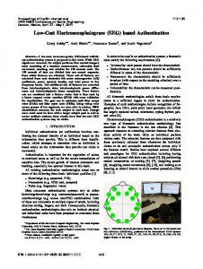
For the next case the cost function given by equation (13) was used. Figure (3) shows the trajectories resulted from the composite cost function which considers the correlation
d = W(2F x x x .F x x + 2F y y x .F y y + 4F x x y ) 6
between flight time, flight altitude and aircraft total acceleration. Results are obtained for three cases of: (a) minimum time-acceleration (MTA) trajectory (i.e. k=0), (b) minimum altitude-acceleration (MAA) (i.e. k=1) .In this example weighting parameters are assumed to be: W1 = 1, W2 = 2, W3 = 1 . Figure (4) illustrates these computed optimum flight trajectories on the terrain surface.
Figure 3. Optimum TF/TA Trajectories based on the minimum Time – Acceleration (k=0) and Minimum Altitude- Acceleration Criteria
Figure 1. MQ Model of The Digital Terrain Data
Figure 4. Optimum MTA (k=0) and MAA (k=1) Trajectories Over the Terrain Surface
6. CONCLUSION Traditionally, path-planning methods offer only two different strategies, known as geometric and dynamic path planning methods. However, they do not discuss any algorithmic approach to incorporate the dynamic characteristics of the flying vehicle when it comes to incorporating the dynamics. Inclusion of dynamic constraints at the planning stage often leads to timeconsuming nonlinear dynamic optimization that may not be of practical applications, especially if the aircraft dynamics model and physical constraints are complex such as the case of TF/TA flights. The new methodology described in this work offers a systematic approach to use the so called “performance index” or cost function as the basic tool to
Figure 2. Optimum TF/TA Trajectories based on Minimum Time (k=0), Minimum Altitude (k=1) and Minimum Time-Altitude Criteria
7
incorporate the dynamics of the aircraft in the process of trajectory planning. Moreover, by using non-dimensional parameters a better understanding of the dynamic terms are provided.
BIOGRAPHIES Seyed M. Malaek is an Associate Professor at the Sharif University of Tech., Tehran, Iran. His research interests include airplane design, flight performance optimization and Air Traffic Management. He is the author of one book in flight dynamics and over 40 papers in the areas indicated above. He has one patent on rotary cockpit for single seat aircraft. Dr. Malaek obtained his M.S. degree in 1986 and his Ph.D. in 1990 from University of Kansas U.S.A.
ACKNOWLEDGEMENT Authors wish to thank Sharif University of Technology Research Council for their support during this research.
REFERENCES [1] Malaek, S.M.B., Kosari, A. R., “A Novel Minimum Time Trajectory Planning in Terrain Following Flights,” IEEE Aerospace Conference, Big sky, MT, 2003.
Amir Reza Kosari is a Ph.D. Student at the Aerospace Engineering Department of the Sharif University of Tech., Tehran, Iran. His research interests include Trajectory Optimization, Optimal Guidance, Control and Astronautics. He is the author of five papers in the areas indicated above. Mr. Kosari obtained his B.S. degree in 1998 from Amirkabir University, Tehran, Iran and his M.S. degree in 2001 from Sharif University of Technology, Tehran, Iran.
[2] Denton, R.V., Froeberg, P. L., “A new Technique for Terrain Following / Terrain Avoidance Guidance Command Generation,” AGARD paper AGARD-CP-387, 1985. [3] Menon, P.K.A., Kim, E., and Cheng, V.H.L., “Optimal Trajectory Synthesis for Terrain – Following Flight,” Journal of Guidance, Control, and Dynamics, Vol. 14, No. 4, 1991, pp.807-813. [4] Lu, P., and Pierson, B.L., “Optimal Aircraft Terrain Following Analysis and Trajectory Generation,” Journal of Guidance, Control, and Dynamics, Vol. 18, No. 3, 1995, pp.555-560. [5] Cheney, E. W. and Light, W. A. t, A Course in Approximation Theory, Brooks Cole, 1999.
Sadegh Jokar is a Ph.D. Aspirant at the Mathematical Sciences Department of the Sharif University of Tech., Tehran, Iran. His research interests include Approximation Theory , Specially he works in Multivariate approximation and Interpolation by Radial Basis Functions and Best Approximation by Polynomials. Mr. Jokar obtained his B. S. degree in 2001 from Islamic Azad University, Central Tehran Branch, Iran and his M.S. degree in 2003 from Sharif University of Technology, Tehran, Iran
[6] Fasshauer, G. E., Meshfree Methods, to appear in Handbook of Theoretical and Computational Nanotechnology, M. Rieth and W. Schommers (eds.). [7] Chen, C. S., Hon, Y. C. and Schaback, R., Scientific Computing with Radial Basis Functions, working on manuscript. [8] Beatson, R. K., Light, W. A., and Billings S., “Fast solution of the radial basis function interpolation equations: domain decomposition methods”, SIAM J. Sci. Comput. 22 (2000), 1717-1740. [9] Abell, Martha L., James P. Braselton. The Maple V handbook. 1994 519.4028553.
8