Available online at www.sciencedirect.com
ScienceDirect Procedia CIRP 46 (2016) 456 – 459
7th HPC 2016 – CIRP Conference on High Performance Cutting
Dynamic behavior of ultra precision feed axis at increased velocities Arne Bloema,*, Christian Schencka, Bernd Kuhfussa a
bime Bremen Institute for Mechanical Engineering, MAPEX Center for Materials and Processing, University of Bremen,Badgasteiner Str. 1, Bremen 28359, Germany
* Corresponding author. Tel.: +49-421-218-64805. E-mail address:
[email protected]
Abstract The processing speed of machine tools for ultra precision manufacturing are low compared to precision manufacturing to satisfy the precision requirements. To increase the productivity and develop machines for ultra precision high performance cutting (UP-HPC) it is essential to examine and compensate dynamic effects. In this work the positioning behavior of an ultra precision feed axis at different setpoint velocities is analyzed and compared to a high speed feed axis. It is observed that the ultra precision feed axis has a large overshoot of several micrometers if the velocities are increased. Further, the decay time of the ultra precision feed axis exceeds the decay time of the high speed feed axis by more than factor two. These two characteristics increase the production time, because of long tool paths and many reversal points, which are often required to keep the kinematic roughness low, especially in ultra precision raster milling. 2016The TheAuthors. Authors. Published by Elsevier B.V.is an open access article under the CC BY-NC-ND license © 2016 Published by Elsevier B.V This (http://creativecommons.org/licenses/by-nc-nd/4.0/). Peer-review under responsibility of the International Scientific Committee of 7th HPC 2016 in the person of the Conference Chair Prof. under responsibility of the International Scientific Committee of 7th HPC 2016 in the person of the Conference Chair Peer-review Matthias Putz. Prof. Matthias Putz Keywords: Ultra precision; Machine tool; Roughness; Dynamic behavior
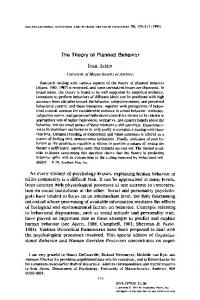
1. Introduction Ultra precision machining is a method to produce parts with optical surfaces with a roughness of few nanometers and form deviations better than one micrometer, even for large parts [1]. One specific example for ultra precision machining is the ultra precision raster milling with a fly cutter. In this case the fly cutter is equipped with a single diamond cutting edge. The work piece is machined in single lines, see Fig. 1.
Fig. 1. Raster milling tool path and kinematic roughness (not to scale)
The accuracy is achieved by using diamond tools and suitable work piece materials; additionally, the machine tool is protected against environmental influences like temperature, fluctuations and vibrations. Dynamic deviations are prevented by soft accelerations. Last but not least a proper path planning is essential, which influences the kinematic roughness. The kinematic roughness is the roughness that is imprinted on the work piece because of the fly cutting principle, the tool shape and the tool path. To reduce the kinematic roughness the single cuts of the diamond tool need to be close together. In z-direction this is achieved by keeping the distance dl between the single cutting lines small [2]. This results in very long tool paths and many reversal points. In feeding direction the kinematic roughness is influenced by the distance dw between each single cutting event. A reduction is achieved by using a low velocity for the x-axis in relation to the spindle speed [2]. Since the spindle speed is limited, this also limits the maximum velocity of the feed-axis to attain a low roughness.
2212-8271 © 2016 The Authors. Published by Elsevier B.V. This is an open access article under the CC BY-NC-ND license (http://creativecommons.org/licenses/by-nc-nd/4.0/). Peer-review under responsibility of the International Scientific Committee of 7th HPC 2016 in the person of the Conference Chair Prof. Matthias Putz doi:10.1016/j.procir.2016.04.040
Arne Bloem et al. / Procedia CIRP 46 (2016) 456 – 459
Similarly, to reduce negative effects of dynamic loads the velocity and accelerations need to be kept small as well, and points of higher accelerations, like the reversal points, are placed outside the work piece. All this necessary steps result in very long production times of multiple hours or even days per workpiece. To decrease the production time new methods are required to achieve high accuracy at increased velocities. This particular work focuses on the analysis of the dynamic behavior of ultra precision machine tools. For this means the positioning characteristics of an ultra precision milling machine are measured at different velocities, including values above those normally used in production, and compared to the characteristics of a high speed machine tool. 2. Positioning behavior To analyze the dynamic behavior positioning tests are conducted. For this reason a single feed axis is accelerated to different velocities and stopped at a defined position. This enforces large accelerations at the halting point. The positioning behavior is measured with a position sensor and analyzed with the parameters overshoot, run-in velocity and decay time.
457
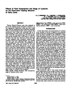
of 2 µm. The maximum velocity of the ultra precision (UP) feed axis is 2 m/min, which is measured in increments of 0.01 m/min up to 0.1 m/min and after that in increments of 0.05 m/min. The high speed (HS) feed axis is measured up to 30 m/min in increments of 0.1 m/min. Every measurement is repeated five times. For both measurements the feed axis is chosen that is directly connected to the machine base to minimize influences of other feed axes. An example of the measurements with a setpoint velocity vset = 400 mm/min is shown in Fig. 2. The characteristics that are analyzed and discussed in the next chapters are the overshoot 'xo which is the largest deviation to the end position in negative direction; the run-in velocity vin which is the velocity of the feed axis when it enters the measurement range of the sensor; and decay-time 'td which is the time between the first reaching of the end position and reaching a given standstill window. Quite surprising are the vibrations of the UP feed-axis. The source was not part of this study but the vibrations were reproduced with different machine-tools. 2.1. Overshoot The first point of attention is the overshoot 'xo of the different feed-axis. Since static errors are not part of this discussion the end position of the feed axes is used as reference for the overshoot. The results for different setpoint velocities are shown in Fig. 3.
Fig. 2. Illustration of overshoot 'xo, the run-in velocity vin and decay time 'td (setpoint velocity vset = 400 m/min)
The ultra precision machine tool that is used for the measurements is a Nanotech 350 Freeform Generator. The positions are measured with a capacitive sensor (Physik Instrumente D-510 PISeca) with a measurement range of 50 µm, a dynamic resolution of 0.5 nm and a linearity error of less than 50 nm. For comparison with a non ultra precision machine a high speed milling machine (Mikromat 4V HSC) is tested. Based on the assumption that the positioning behavior features larger overshoots, a sensor with a larger measurement range is applied. In this case a laser triangulation sensor (Micro Epsilon optoNCDT 2300) is used with a measurement range of 10 mm, a resolution of 0.15 µm and a linearity error
Fig. 3. Overshoot of the UP-axis and HS-axis (including three-fold standard deviation)
The overshoot 'xo,HS of the HS feed axis is monotonically increasing up to a velocity of 6 m/min, where it reaches a value of about 5.4 µm. With higher setpoint velocities the curve progression becomes more complex, but it still increases by trend, until it reaches its maximum value of 12.8 µm at a velocity of 14 m/min. Between 14 and 30 m/min the overshoot 'xo,HS decreases again. In contrast 'xo,UP of the UP feed axis reaches its maximum of 2.9 µm with a rather
458
Arne Bloem et al. / Procedia CIRP 46 (2016) 456 – 459
low setpoint velocity of 0.15 m/min. Furthermore, the maximum is more distinct and the curve progression becomes unsteady behind the maximum. Especially two characteristics of the overshoots are remarkable. One is that 'xo of the HS feed axis is smaller than 'xo,UP of the UP feed axis at low velocities. Only at velocities below 0.03 m/min the UP feed axis performs better. The other remarkable characteristic is the actual value of 'xo,UP of the UP feed axis. Even so the sudden halt is a harsh test for an UP feed axis; values of multiple micrometers are unexpected of a machine tool, which is used for positioning in the nanometer range. However, test measurements on a different UP machine tool (Precitec Freeform 3000) show similar results. The large overshoot is especially problematic in the context of decreasing the production time, since higher accelerations of the feed axis during the cutting process can’t be completely avoided anymore. Furthermore the overshoot 'xo of both feed axis is unsteady at higher velocities and partly decreases. Beside a higher measurement uncertainty of the laser triangulation sensor, a possible explanation might be the deceleration behavior. For this reason the run-in velocities are analyzed.
the intensity of the deceleration and the overshoot is likely. However, this connection is not as clear for the UP feed axis, as the maxima and curve shape hardly match. This indicates a more complex deceleration behavior.
2.2. Run-in velocity The run-in velocity vin is defined as the velocity with which the feed axis enters the measurement range of the sensors at a distance of 'xin to the end setpoint position. To ensure reliable measurements this distances are set to 'xin,HS = 4 mm (laser sensor) and 'xin,UP = 8 µm (capacity sensor). For comparison vin is also measured at 'xin,HS = 8 µm. The results are displayed in Fig. 4. At a measurement distance 'xin,HS of 4 mm the HS feed axis features the expected behavior. The run-in velocity vin,HS is equal to the setpoint velocity vset up to a value of 7 m/min. After that point it starts to saturate around a run-in velocity vin,HS of 8 m/min. At a measurement distance 'xin,HS of 8 µm the behavior of the high speed machine tool is more complex. The run-in velocity vin,HS has already fallen below the setpoint velocity vset. Overall the run-in velocity vin,HS is complex but converges to zero for higher values of vset. In contrast even at this low distance the UP feed axis reaches the velocity setpoint vset, however, only up to a value of 0.15 m/min. With higher values the run-in velocity vin,UP of the UP feed axis starts to oscillate around a mean value of about 0.156 m/min. The measurements display that the deceleration of the HS feed axis is noticeably higher in comparison to the UP feed axis or the deceleration of the HS feed axis starts in a greater distance to the setpoint position. A possible explanation of this behavior is that UP machine tools are probably more optimized to have a constant velocity, since variations of the feeding velocity inevitably result in deviations of the surface roughness and induce vibrations by acceleration and jerk forces. The observation that the velocity of the UP machine is equal to the setpoint velocity vset even at small distances to the end position supports this explanation. In comparison to the results of section 2.1 the different maxima of the run-in velocity of the HS feed axis roughly match the maxima of the overshoot. A connection between
Fig. 4. Run-in velocity of the UP-axis and HS-axis (including three-fold standard deviation)
2.3. Decay time The last point of observation is the decay time 'td of the two machine tools. The measured time interval begins as soon as the feed axis reaches the end position for the first time and ends when the amplitude of the vibrations fall below a given threshold 'xd. The two machine tools aim at different accuracy levels. Hence, two different threshold values are chosen to identify the decay times; 'xd,HS = 500 nm, 'xd,UP = 75 nm. The results are shown in Fig. 5. The decay time of the HS feed axis 'td,HS increases up to a setpoint velocity vset of 2.1 m/min but hardly exceeds 1 s. However the decay time of the UP feed axis 'td,UP keeps increasing until the maximum setpoint velocity is reached. At that point 'td,UP features a value of about 2.6 s. Beside the high overshoot of the UP feed axis the decay time 'td,UP is the second characteristic that needs optimization to enable higher processing speeds. To achieve a low kinematic roughness the line distance dl of the milling process must be low. This highly increases the number of lines and therefore also the number of reversal points. Since the processing of the next line cannot begin until the feed axis settles (x-axis in Fig. 1) the long decay time cumulates to significant time extension of the overall process.
Arne Bloem et al. / Procedia CIRP 46 (2016) 456 – 459
459
carried out as more extensive measurement series. This could enable a more detailed insight into the behavior of multiple interpolating ultra precision feed axes. 4. Discussion and conclusion
Fig. 5. Decay time of the UP-axis and HS-axis (including three-fold standard deviation)
3. Dynamic behavior of interpolating feed axes In the previous measurements only a single feed axis is observed at a time. This enables a good impression of the feed axis positioning behavior and its control mode. But the production of curved surfaces demands multi-axes motion. When feed axes interpolate the resulting interactions must be analyzed. This requires a two dimensional measurement system with a sufficient accuracy for ultra precision manufacturing, a sufficient range and an adequate time resolution. Such a measurement system is newly introduced in [3]. The still experimental setup is based on the tracing of images of speckle patterns which are created when a laser beam is reflected by a not optical surface. It already provides the required resolution in nanometer range and high accuracy if the travelling range is not too large. A first test measurement with this new measurement system on an ultra precision machine tool is illustrated in Fig. 6
In the previous chapter the positioning behavior of an ultra precision machine tool is analyzed and compared to a high speed machine tool to identify characteristics that need attention to decrease the processing time of ultra precision machine tools. The two identified main issues are the overshoot 'xo and the decay time 'td. The overshoot 'xo,UP of the ultra precision machine tool has a maximum value of 5.4 µm. The decay time 'td,UP reaches a maximum value of 2.5 s. Both values decrease the possible maximum machining speed, at which the requirements for ultra precision machining still can be met. The overshoot directly reduces the velocity; the decay time determines the required time intervals for the machine axis to settle. For example, if a square surface of 10 mm edge length should be machined to a surface roughness of 10 nm with a round diamond tool with a diameter of 1 mm, this results in roughly 1120 single lines that need to be processed. Calculating one reversal point per line these result in an overall settle time of nearly 45 minutes. A direct correlation between 'xo,UP and 'td,UP is not observed. The overshoot 'xo,UP reaches its maximum value at a setpoint velocity vset of 0.15 m/min. However, the decay time 'td,UP increases up to the maximum setpoint velocity. On the other hand, the ultra precision machine tool retains its setpoint velocity close to the end position. This indicates that the machine tool axis is optimized to rather keep a constant velocity instead of a smooth positioning behavior. A focus point of future research is the compensation of the portrayed effects. This requires new methods to combine the low overshoot and decay time of the high speed machine tool with the precision and constant velocity of an ultra precision machine tool. Since, this places a high demand on the control mode; adaptive controllers based on state-space models are researched.
Acknowledgements The authors would like to thank the German Research Foundation (DFG) for funding this work as a part of the Research Unit FOR1845 “Ultra-Precision High Performance Cutting”. References
Fig. 6. Circular shape test of two interpolating UP-axes
I n this case a circular motion with a diameter of 10 µm is traced. The velocity is set to 6 mm/min. This measurement already displays a complex behavior due to the short cycle times and the superimposing vibrations of the two feed axes. In future works these measurements need to be verified and
[1] Brinksmeier E, Preuß W. Micro-machining. Phil. Trans. R. Soc. A 2012; 370:3973–92. [2] Wang S J, To S, Cheung C F. An investigation into material-induced surface roughness in ultra-precision milling. The International Journal of Advanced Manufacturing Technology, 68, 2013, p. 607-616 [3] Bloem A, Schenck C, Kuhfuß B. 2D position sensor based on speckle correlation. Proceedings of the 4M/ICOMM2015 International Conference on Micromanufacturing. Milano (Italy); 2015; p. 541-544