Dynamic Design of a Reluctance Synchronous Machine utilising Python Scripting in FLUX 10.2 Wright J.G.(1), Cronje W.A., (1) Meyer A.S. (1) (1)
University of the Witwatersrand, Johannesburg, South Africa,
[email protected]
Abstract : The Reluctance Synchronous Machine (RSM) is fast becoming an alternative in variable speed applications owing to its many favorable characteristics. A four-pole RSM dynamic design procedure is presented utilising Python and the embedded PyFLUX language in FLUX 10.2. The design approach focuses on maximum mean torque and minimum torque ripple. Several geometric parameters are varied consecutively - once the choice of one geometric parameter is made where maximum mean torque and minimum torque ripple occurs the next geometric parameter is varied utilising the previous optimised parameters. The final design includes six rotor barriers with β = 0.3 , a rotor position from the D-axis of 20 mm, a rotor cutout =0.85 , an airgap length of 0.8 mm and radial rib and tangential web supports set to 2 mm.
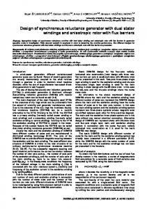
I. Introduction and background The Reluctance Synchronous Machine (RSM) is an AC machine with a three-phase AC stator winding. A transversally laminated 4-pole RSM is shown in Fig. 1 with the relevant geometric parameters and D and Q axes shown. A RSM rotor with a higher D and Q axis inductance difference and ratio results in better RSM performance [4]. The RSM has several advantages that include easy control, synchronous speed, cold rotor, high speed operation and robustness [4]. Improved, low-cost power electronics has allowed the RSM to become a viable option in industry where variable synchronous speed, cool operation and an efficient overall process is required. The main parameter in the control of the RSM is the current vector angle with respect to the Daxis [3]. Maximum Torque Control (MTC) requires a current vector angle of 45 o but when taking into account core losses and saturation can approach higher values closer to 60 o [3]. A design procedure for a 4-pole transversally laminated RSM is presented. This is followed by the implementation of this design in FLUX 10.2 utilising PyFLUX. The simulation results of the design procedure and the final design are then given followed by suggestions for future work.
Fig. 1 Cross section of a 4-pole transversally laminated RSM.
II. RSM design procedure As the RSM rotor rotates there is an interaction between the stator slots and rotor barriers that results in a ripple in the electromagnetic torque. The desirable design outcome is to have maximum mean torque and minimum torque ripple to allow minimal vibrations, acoustic noise and possible mechanical resonances. The rotor is rotated through a predefined angle with a constant current vector angle. The mean electromagnetic torque and torque ripple are then defined as: n
T ex n a T max −T min T ripple= T mean T mean =∑
where a n T ex T max T min
(1) (2)
= First element in electromagnetic torque waveform. = Total number of elements in electromagnetic torque waveform. = Electromagnetic torque at position x in the electromagnetic torque waveform. = Maximum electromagnetic torque. = Minimum electromagnetic torque.
A four-pole induction machine stator identical to that shown in Fig. 1 is utilised with a transversally laminated RSM rotor topology. The geometric parameters changed during the design as shown in Fig. 1 are listed in Table 1. The design as outlined in Fig. 2 investigates the geometric parameters effect on torque production in a linear progression. Essentially, a parameter is varied and the torque waveform analysed to extract the mean torque (eqn. 1) and torque ripple (eqn. 2). Thereafter, the parameter value is chosen where maximum mean torque and minimum torque ripple occurs. This value is then utilised for the design procedure that follows where the process is repeated for the next parameter. The order in which the design proceeds is N rb and β together, W p , α and g . Intuitively, l tw and l rr should be zero. However, this is contradictory to mechanical strength requirements. Thus, l tw and l rr are changed for purely investigative purposes. Table 1 Parameters to be changed during design procedure.
Parameter
Description
N rb
Number of rotor barriers
β=
b bw
bbw +blw Wp
α=
τ τ
Insulation ratio Position of first rotor barrier Pole pitch to pole span ratio
p
g
Length of airgap
l tw
Length of tangential webs
l rr
Length of radial ribs
Fig. 2 Linear progression approach for design procedure
III. Implementation of RSM design in FLUX The design procedure is implemented in FLUX 10.2 using Python scripts incorporating PyFLUX and Python [5]. The FLUX 3-D beta solver utilised allows all required model development, solving and post-processing to be incorporated into one environment. This also allows for insight into the relevant PyFLUX commands required for solving and post-processing. The geometry of the RSM is developed parametrically to allow for quick changes in the geometry. The three stator windings have two parallel paths each assigned as stranded coil conductors with imposed currents defined by three I/O parameters sinusoidally dependant on twice the rotor angle and current vector angle of 45 o . Separate FLUX projects are created for each parameter and Python files utilised to change the parameter during the design as shown in Fig. 3. A distinct modular approach allows reuse of the Python file structure with only slight modifications required.
Fig. 3 Modular structure of Python file for variation of required geometric parameter.
IV. Design results and analysis IV-A Variation of N rb and Mean torque and torque ripple versus beta plots for a range of rotor barriers are shown in Fig. 4. Maximum mean torque occurs around =0.3 for rotor barrier numbers higher than five and minimum torque ripple occurs between =0.1 to =0.3 . A value of =0.3 is chosen along with N rb=6 to allow for ease of manufacturing and mechanical strength. IV-B Variation of W p Torque and torque ripple versus W p is shown in Fig. 5. Maximum mean torque occurs around W p =20 and minimum torque ripple at W p =25 . A value of W p =20 is chosen.
Fig. 4 Mean torque and torque ripple versus beta for a range of rotor barriers.
Fig. 5 Torque and torque ripple versus position of rotor barrier.
IV-C Variation of Torque and torque ripple versus is shown in Fig. 6. Maximum mean torque as well as minimum torque ripple occur at =0.85 . A value of =0.85 is chosen.
Fig. 6 Torque and torque ripple versus pole pitch to pole span ratio
IV-D Variation of g Torque and torque ripple versus airgap length is shown in Fig. 7. Mean torque increases significantly as the airgap length decreases. However, torque ripple also increases as the airgap length decreases. Also, consideration needs to be given to whether an airgap of 0.4 mm is obtainable considering manufacturing tolerances. The airgap is left as 0.8 mm.
Fig. 7 Torque and torque ripple versus airgap length.
IV-E Variation of ltw
and l rr
Both l tw and lrr should be zero to maximise saliency however mechanical requirements impede this. Torque versus l tw and l rr plots shown in Fig. 8 reveal that mean torque decreases as l tw and lrr increase. Torque ripple increases when l tw is close to zero as a result of increases in permeance harmonics. Traditionally, RSM designers have chosen the length of l tw and l rr to be a multiple of the lamination thickness [1,2]. Initial design choices of l tw =2 mm and l rr =2 mm (4x lamination thickness) are chosen. A cross section of the final RSM is shown in Fig. 9.
Fig. 8 Torque versus tangential web and radial rib length
V. Future work Future work and improvements include: • Mechanical Finite Element Analysis to investigate the mechanical strength of the rotor when rotating at nominal speed (1500 rpm) and undergoing mechanical torque changes.
• •
•
Choice of the current vector angle made dynamically during the design to ensure MTC at each simulation step. With no induction machine rotor (no rotor bars), the thermal operating point of the machine changes. An investigation into whether more current can be placed in the stator windings to generate more electromagnetic torque for the final mechanical process can be performed. A prototype of the final RSM should be built and tested in a laboratory environment for verification of performance.
Fig. 9 Cross section of final RSM design
VI. Conclusions A RSM design is dynamically developed using PyFLUX and generic Python in FLUX 10.2. The linear progression approach to the design is outlined and the overall structure of each Python file presented revealing a modular reusable approach. Geometric parameter values are chosen based on where maximum mean torque and minimum torque ripple occurs. After choosing N rb=6 and =0.3 , W p =20 is chosen. Cutout value =0.85 is then chosen. A smaller airgap allows for more torque to be generated but with more torque ripple and owing to manufacturing constraints the nominal airgap length of 0.8 mm is maintained. Finally, maximum mean torque is obtained when ltw and lrr are zero however values of 2 mm are chosen to allow for mechanical rigidity.
VII. References [1] [2] [3] [4] [5]
Niazi, P. “Permanent Magnet Assisted Synchronous Reluctance motor design and performance improvement”, School of Electrical Engineering, Texas A&M University, Texas, USA, 2005. Haataja, J. “A comparative performance study of four-pole induction motors and synchronous reluctance motors in variable speed drives”, Lappeenranta University of Technology, Lappeenranta, Finland, 2003. Bomela, X. & Kamper, M. “Effect of machine design on performance of reluctance synchronous machine”, Conference Record of the 2000 IEEE Industry Applications Conference, 2000, Vol. 1, pp. 515-522. Betz, R. Lagerquist, R. Jovanovic, M. Miller, T. & Middleton, R. “Control of synchronous reluctance machines”, IEEE transactions on industry applications, 1993, Vol. 29, pp. 1110-1122 FLUX users guide, www.cedrat.com