Dynamic energy-aware sensor configuration in multi-application monitoring systems Ozgun Pinarer, Yann Gripay, Sylvie Servigne, Ozgovde Atay, Atilla Baskurt
To cite this version: Ozgun Pinarer, Yann Gripay, Sylvie Servigne, Ozgovde Atay, Atilla Baskurt. Dynamic energy-aware sensor configuration in multi-application monitoring systems. Pervasive and Mobile Computing, Elsevier, 2017, 41, pp.192-204. .
HAL Id: hal-01585263 https://hal.archives-ouvertes.fr/hal-01585263 Submitted on 12 Sep 2017
HAL is a multi-disciplinary open access archive for the deposit and dissemination of scientific research documents, whether they are published or not. The documents may come from teaching and research institutions in France or abroad, or from public or private research centers.
L’archive ouverte pluridisciplinaire HAL, est destinée au dépôt et à la diffusion de documents scientifiques de niveau recherche, publiés ou non, émanant des établissements d’enseignement et de recherche français ou étrangers, des laboratoires publics ou privés.
Dynamic Energy-Aware Sensor Configuration in Multi-Application Monitoring Systems Ozgun Pinarera,b , Yann Gripaya , Sylvie Servignea , Atay Ozgovdeb , Atilla Baskurta a
Univ Lyon, CNRS, France INSA-Lyon, LIRIS, UMR5205, F-69621 Email:
[email protected] b Galatasaray University Ciragan Cad. No:36 34349 Istanbul, Turkey Email: {opinarer, aozgovde}@gsu.edu.tr
Abstract A typical pervasive monitoring system like a smart building depends on an infrastructure composed of hundreds of heterogeneous wireless sensor devices. Managing the energy consumption of these devices poses a challenging problem that affects the overall efficiency and usability. Existing approaches for sensor energy consumption typically assume a single monitoring application to consume sensor data and a static configuration for sensor devices. In this paper, we focus on a multi-application context with dynamic requirements and multi-modal sensor devices. We present 3SoSM, an approach to optimize interactions between application requirements and wireless sensor environment in real-time. It relies on an energy-aware dynamic configuration of sensor devices to lower energy consumption while fulfilling application requirements. To bind together sensor configuration and dynamic management of data streams, we design a sustainable multi-application monitoring system architecture for pervasive environments that collects application requirements for sensor data streams and optimizes them into sensor configurations. To demonstrate the effectiveness of our approach, a set of experiments are designed in the context of smart buildings. We comparatively evaluate our approach to show how dynamic sensor configuration for multiple monitoring applications indeed outperforms the mainstream duty-cycling method. Keywords: pervasive environment, sensor data management, continuous query processing, wireless sensor network
Preprint submitted to Pervasive and Mobile Computing
August 3, 2017
1
2 3 4 5 6 7 8 9 10 11 12 13 14 15 16 17 18 19 20 21 22 23 24 25 26 27 28 29 30 31 32 33 34 35
1. Introduction Smart building applications have long gained attention in the scientific community and nowadays in the industry. Buildings, whether smart or not, are among the primary consumers of the available energy sources today. Therefore, considerable effort is poured into the design of smart buildings where energy consumption is tried to get decreased without sacrificing the satisfaction of the occupants. To accomplish this aim, the components of the building itself, as well as the context of its users, should be continuously monitored by means of streams of data from sensory inputs. A typical pervasive monitoring system like a smart building consists of multi-modal wireless sensor devices that are equipped with sensing, processing and communication facilities. Sensing part can measure physical quantities about the environment with some given sampling rate (sampling frequency), processing part is able to do some computation on the measured values and communication part is able to listen and send data packets to other sensor devices. These deployed wireless devices are autonomous in terms of energy: they have limited energy and battery lifetime. Smart building technology mainly relies on such wireless sensing infrastructure. In this field, initial commercial solutions are Building Automation Systems where a specific set of functionalities such as heating and ventilation control and lighting management is implemented by a single vendor. However, as the sensor infrastructure is becoming a standard component incorporated into the design and construction of the modern buildings, flexible application development by a third party is becoming an issue rather than the infrastructure itself. In this context, one of the main contributions of this paper is to allow multiple applications to exploit the same smart building infrastructure while considering energy consumption of the sensor devices in this infrastructure. Our energy-aware monitoring system continuously adapt to various application requirements, to building actual context and to user configuration. These applications operate on a network of multi-modal wireless sensor devices and use declarative continuous queries to exploit sensor data streams. Application requirements as declared by the application developer can be fulfilled in a multitude of ways: our method translates these requirements as energy efficient acquisition and transmission schedules for the wireless sensor 2
52
network. We propose Smart-Service Stream-oriented Sensor Management (3SoSM), an approach to optimize interactions between application requirements and the wireless sensor environment in real-time. The core of our approach is the definition of a Schedule Time Pattern with acquisition, transmission and reception actions for each device configuration. The dynamic reconfiguration of devices is performed through the real-time update and optimization of Schedule Time Patterns according to application requirements that may change over time. With this approach, we expect to avoid unnecessary data measurements that may occur with static configuration and to promote grouped or even compressed data transmission when possible. In this article, Section 2 presents an overview of our multi-application monitoring system architecture. Formalization of our approach is explained in Section 3 and the energy-aware optimization process is detailed in Section 4. Section 5 gives a brief description of our experimental platform to implement our approach and Section 6 describes the experiments we conducted. Experiment results are discussed in Section 7. Related works are given in Section 8 and finally, conclusions are given in Section 9.
53
2. Overview of 3SoSM
36 37 38 39 40 41 42 43 44 45 46 47 48 49 50 51
54 55 56 57 58 59 60
61 62 63 64 65 66 67 68 69 70
Our 3SoSM approach focuses on a multi-application monitoring system with multi-modal sensor devices (i.e. devices that can measure different physical quantities) and provides finer sensor configuration than duty-cycle and similar techniques. Our proposition of dynamic sensor management based on real-time application requirements is performed at the gateway level, in order to optimize energy consumption of sensor devices independently from the application layer and/or the query engine. 2.1. Monitoring Architecture for Smart Building Applications In this study, we adopt a “declarative monitoring architecture”, built upon a Pervasive Environment Management System (PEMS) as presented in [1, 2, 3]. Using declarative (SQL-like) continuous queries, an application can easily interact with distributed devices like sensors. Figure 1 presents our declarative monitoring application that has 4 main layers: Application, PEMS Query Engine, PEMS Gateway and WSN (Wireless Sensor Network). Application layer provides end-user access to the monitoring system. Application requirements are defined at this layer and are declaratively expressed as a set of continuous queries over distributed services [1]. PEMS 3
71 72 73 74 75 76 77 78 79 80 81
Query Engine is responsible for managing query executions of queries coming from the Application layer. This layer integrates sensor devices as nonconventional, dynamic and heterogeneous data sources. To manage that, it includes a continuous query engine that interacts with services provided by the environment, in particular sensor services. PEMS Gateway stands for managing bidirectional communication and interactions between PEMS Query Engine and WSN. WSN layer represents wireless sensor devices that acquire physical quantity measures and can communicate with other sensor devices and physical gateways. We use the Service-Oriented Continuous Query (SoCQ) framework [1] for the PEMS Application1 ApplicationN Query Engine. The SoCQ engine handles PEMS Query Engine a multi-application mechanism and supPEMS Gateway ports multiple parameterized stream subWSN scriptions to the same device. Moreover, it supports real-time user configuration of applications and context-aware applications Figure 1: Declarative Monitoring Architecture. through queries that can dynamically combine data, streams and services. The user may insert complex continuous queries with conditions over data streams to trigger new interactions with services during their execution. Interactions with services (discovery, invocations of methods, subscriptions to data streams) are handled by PEMS Gateway. However, the SoCQ Engine itself does not overcome the reconfiguration of sensor devices, and thus assumes a pre-existing static configuration. Like for other approaches presented in the Related Works section, it is an issue for the energy enhancement of the system. ...
82 83 84 85 86 87 88 89 90 91 92 93 94 95 96 97
98 99 100 101 102 103 104 105 106 107
2.2. From Dynamic Application Requirements to Dynamic Sensor Configurations We consider that applications define their requirements as a set of continuous queries over parameterized data streams produced by sensor devices. For instance: “Application A1 computes the average temperature over the last 10 minutes, with an update every 5 minutes, with an accuracy of 1 second and a maximum latency of 1 minute”. In this example, the application requests temperature measure data streams from all devices with temperature sensors. To express the application requirements concerning sensor data management, we consider the following parameters targeting sensor measures: • temporal 4
121
window introduces the time interval for calculating the result (for the given example: 10 min); • update periodicity stands for the refreshing rate of the result (5 min); • acquisition periodicity represents the temporal accuracy of measures (1 sec); • maximum latency presents the maximum acceptable delay between the acquisition of data and its transmission to the PEMS layer for result calculation (1 min). temporal window and update periodicity concern the computing of the result, whereas acquisition periodicity and maximum latency are related to acquisition/transmission of data by sensor devices. Here, we propose a novel approach: management and optimization of the real-time application requirements to enhance the energy consumption of the whole system. To fulfill the application requirements, we define a Schedule Time Pattern for each sensor device and configure devices accordingly. Our approach assumes that sensor devices are dynamically configurable [4].
122
3. 3SoSM Formalization
108 109 110 111 112 113 114 115 116 117 118 119 120
123 124 125 126
127 128 129 130 131 132 133 134 135 136 137 138
139 140 141
We consider that application requirements are parameterized stream subscription requests and the network topology is a tree topology. A solution to our optimization problem is individual Schedule Time Patterns, namely sco-patterns. 3.1. Application Requirements Let D be the set of wireless sensor devices in the WSN environment. Each sensor device di ∈ D may have multiple modalities to acquire different physical quantity measures mi ∈ M , e.g., temperature, humidity. Application requirements are defined in terms of data source requirements: targeted sensors d and requested measures m; and of temporal requirements: temporal window β, update periodicity pupd , acquisition periodicity pacq and maximum latency λ. The unit is the second (or millisecond, if required). For clarity, we do not present β, pupd in this paper. We then represent application requirements on sensors at a given time instant by a set of parameterized subscription requests S = {s1 , s2 , . . . , sn }, where: + + si = (di , mi , pacq i , λi ) ∈ D × M × N × N Example 1. Suppose two applications with the following requirements on 6 sensors: Application 1: Temperature (mT ) of sensors d1 , d3 , d5 with an acquisition 5
142 143 144 145 146 147 148
149 150 151 152 153 154 155 156 157 158 159 160 161 162 163 164 165 166 167 168 169 170 171 172 173
174 175 176
periodicity of 2 sec and a latency of 4 sec; Application 2: Humidity (mH ) of sensors d3 , d4 , d5 , d6 with an acquisition periodicity of 5 sec and a latency of 3 sec. Based on the previous notation, all application requirements are represented by a set of parameterized subscription requests: S = {(d1 , mT , 2, 4), (d3 , mT , 2, 4), (d5 , mT , 2, 4), (d3 , mH , 5, 3), (d4 , mH , 5, 3), (d5 , mH , 5, 3), (d6 , mH , 5, 3)} 3.2. Network Topology To transmit data to the central base station (where results are computed), we suppose that deployed wireless sensor devices construct a logical tree (tree topology) where each sensor has only one neighbor to deliver data packets. This tree structure provides a uni-path for each sensor to reach the base station (sink device). In fact, our optimization algorithm relies on known and unique paths, as it does not consider a choice of network paths between two devices. Integrating more complex network topologies, such as mesh networks, would be a future work. However, the tree topology may be updated each time application requirements change, as it triggers a new optimization. For instance [5] proposes a new technique to organize the sensor devices that is likely preferable for outdoor monitoring systems: P-SEP (a prolong stable election routing algorithm). The authors consider two-level sensor device heterogeneities: advanced and normal devices. They propose a clustering mechanism and present new cluster head selecting policy to extend the lifetime of the system (lifetime of the system is evaluated in terms of FND (First Node Dies)). P-SEP puts forth efficient simulation results and network lifetime. Although we do not tackle routing issues, applying our dynamic network behavior due to the dynamicity of the application requirements, with the P-SEP mechanism could produce concrete improvements on the lifetime of the system. In our case, with our assumptions about the network, each sensor device has its own role in the topology based on the current applications and its location: Source (responsible for the data acquisition and transmission) and/or Relay (responsible for the reception and re-transmission), or Sink (responsible for only the reception). Example 2. A tree topology with 6 multi-modal sensor devices and a base station is illustrated in Figure 2. A tree topology has a layered form based on the distance to the base station.
6
Sink
Layer 0
Sensor 0
SR
R
Sensor 1
Sensor 2
Layer 1
S
S
S
S
Sensor 3
Sensor 4
Sensor 5
Sensor 6
Layer 2
Figure 2: A tree-structured topology and different sensor device roles: Source (S), Relay (R), Source+Relay (SR), Sink.
194
3.3. Sco-pattern The idea behind the 3SoSM approach is to create a Schedule Time Pattern for each sensor device. This pattern, described in [6] is a schedule composed of sensor actions, here with three types of actions: acquisition A, reception R, transmission T. Based on their roles, only certain actions are pertinent to sensor devices. Sensor devices can configure themselves with a Schedule Time Pattern, and then execute periodically the scheduled actions: acquire a measure and store it in a memory buffer, transmit all buffered measures one hop towards the sink (and empty the buffer), receive measures from a lower-layer device and store it in a memory buffer. We call this pattern sensor configuration oriented pattern or scopattern. This pattern consists of timestamped events (< timestamp, action > couples) and a length ` (or periodicity) of that pattern. These actions are enclosed by the length of the pattern: event timestamps are in time interval [ 0; ` [. A sco-pattern is denoted by: P = ({(ti , ai )}, `) with ` ∈ N+ , ti ∈ [0; `[, ai ⊂ {Am , T, R} where Am indicates the data acquisition of the physical measure m such as AT for temperature, AH for humidity, etc.
195
4. 3SoSM: Energy-Aware Optimization Process
177 178 179 180 181 182 183 184 185 186 187 188 189 190 191 192 193
196 197 198 199 200 201 202 203
To optimize the energy consumption of the devices, since the communication costs are the most significant part of the energy budget [7], we want to minimize the number of transmission and reception actions of each device: less communication means less consumed energy. We first construct “preliminary” sco-patterns that have a common length with only acquisition actions (Acq) for all the devices. It is then necessary to insert the transmission (Tx) and reception (Rx) actions in these sco-patterns to obtain a solution, composed of the set of complete sco-patterns. A solution is 7
204 205 206 207 208 209 210 211 212 213 214 215
216 217 218 219 220 221 222 223 224 225
226 227 228 229 230
231 232 233
234 235 236
valid if all acquired data traverse the network topology from their source device to the base station before the “latency” associated with that data expires. The optimal solution is a valid solution that minimizes the number of Transmission / Reception actions of each device. The objective of the optimization process is to transform the application requirements into a global schedule and then to build individual scopatterns to configure each device. Application requirements are represented by a set of subscription requests S = {s1 , s2 , s3 , ...}. Hence the energy-aware optimization process can be expressed as a transformation function that gets a set of subscription requests (all subscription requests from all applications) and a network topology N and produces a sco-pattern for each device: f ({s1 , s2 , ..., sn }, N ) = {Pd1 , Pd2 , ...., Pdm }. 4.1. Preliminary Sco-Pattern The preliminary sco-pattern is specific for each sensor device. It is periodic, and its length indicates the periodicity. Each sensor device may have different acquisition periodicities from different applications. However, in order to build a global view of the network, a common length is required: it is the lowest common multiple of acquisition periodicities from all subscription requests. Moreover, the length of the schedule should be greater than any latency of the subscription requests to properly handle data expiration time: The final length is the lowest multiple of this initial common length greater than any data expiration time. Example 3. The common length of the patterns (for the given applications in Example 1) is calculated as: Initial common length `min = LCM (2, 2, 2, 5, 5, 5, 5) = 10 M aximum latency λmax = M AX(4, 4, 4, 3, 3, 3, 3) = 4 F inal length `schedule = 10 sec > λmax Then, based on the periodicity of subscription requests, acquisition actions are defined. Furthermore, each acquisition action is tagged with its maximum latency (from the subscription request). Example 4. Preliminary sco-pattern for d3 with subscriptions {(d3 , mT , 2, 4), (d3 , mH , 5, 3)} : P = ({(0, {A4T , A3H }), (2, A4T ), (4, A4T ), (5, A3H ), (6, A4T ), (8, A4T )}, 10)
8
237 238 239 240 241 242 243 244 245 246 247 248 249 250 251 252 253
254 255 256 257 258 259 260 261
262 263 264 265 266 267 268 269 270 271 272
4.2. Transmission Constraint and Optimization Goal To form a global schedule, we adopt a similar approach to Galpin et al. [8]. A predefined granularity determines the slots in the time space: the schedule is divided into time-slots and each slot may be filled with sensor actions. For the following examples, granularity is set to 0.5 sec (e.g. 20 slots for 10 seconds). The major constraint of the system is that all the acquired data must pass through the network topology up to the base station before the expiration of their “latency” in order to fullfill the application requirements. A transmission action on a sensor device during a single time slot stands for a transmission of all the data (acquired by itself and received from lower-layer neighbors) not yet sent, including acquisitions on the same time slot. This transmission action requires a reception action at the same time slot on the sensor device that receives the data. Besides there are other constraints due to the radio protocol such as a device can only receive data from a single device at a time on the same time slot and a device can not receive and send on the same time slot. 4.3. Searching Optimal Communication Slots We propose an optimization algorithm to choose the optimal communication slots from the preliminary sco-pattern. The optimization process starts by propagating transmission and reception constraints due to the acquisition events in a bottom-up process, and then analyzes the possible reception actions of the base station and tries to find the most energy efficient communication slots, and finally propagates those choices to lower layers and continues the analyze in a top-down process. 4.3.1. Schedule Table Initialization We use a schedule table to represent the sensor action slots for Tx/Rx. Each sensor device has its own schedule and each schedule is composed of two parts: transmission and reception part. The length of the schedule is defined by the common length of preliminary sco-patterns. Each line of the schedule table corresponds to an acquired measure: its transmission action for the transmission part and its reception action for the reception part. The transmission part indicates the possible transmission slots for the sensor device for each acquired measure. According to the latency information λ, every sensor device has the initiative to keep the data (instead of 9
273 274 275 276 277 278 279 280 281
282 283 284 285 286 287 288 289 290 291 292 293 294
295 296 297 298 299 300 301
302 303 304 305 306 307 308
sending it immediately) and send it at an optimal later moment under the condition that this acquired data arrives at the base station before the expiration of its latency. The reception part represents the possible reception slots for each data coming from lower-layer neighbors (zero, one or several depending on the network topology). Schedule Table for Sensor 3, Sensor 1 and Sensor 0 (sink device) are illustrated in Figure 3. We propagate bottom-up constraints for data transmission and reception based on latencies (from preliminary sco-patterns) and on the network topology. Transmission Part. Information from the preliminary sco-pattern is used to fill the transmission part. For a given sensor device, each acquired data and each received data is represented as a line in the transmission part. A line is filled with the residual latency information starting from the time slot where the device acquires the data or from the time slot following the time slot where the device received the data, and until residual latency reaches 0 (in fact, 1 time slot before at 1 hop from the sink, 2 time slots at 2 hops, etc.). For each device d, Td = [ei,j ] is a 2D matrix with dimensions md xn. md is the number of data to transmit and n stands for the number of time slots. ei,j represents a potential transmission event of data i at time slot j: ei,j = λi,j is the residual latency, ei,j = 0 means that data i can not be transmitted at that time slot. Example 5. Transmission parts of the schedules of Sensors 3 and 1 are presented respectively in Figure 3a, 3b. For instance, Sensor 3 measures temperature and humidity values. For A2#1 (first acquisition for humidity), the latency is 3sec. Hence, to send that data, Sensor 3 has 5 slots (t=0,0.5, 1, 1.5, 2 sec) before the latency is expired as it is 2 hops from sink. Transmission part of the schedule of Sensor 1 covers transmission of its own data and also received data from Sensor 3 and 4 (see Fig 3b). Reception Part. For a given sensor device, the reception part is based on the transmission part of the schedules of lower-layer neighbors. Each line represents a data to receive and is linked to one line from the transmission part of the source device. Possible reception slots are filled with the data residual latency from the corresponding transmission time slot. For each device d, Rd = [ei,j ] is a 2D matrix with dimensions md xn where md is the number of data to receive and n stands for the number of time slots. 10
(a) Schedule of Sensor 3 (Acquisition + Transmission).
(b) Schedule of Sensor 1 (Acquisition + Reception + Transmission).
(c) Schedule of Sensor 0 (Sink device) (Reception). Figure 3: Schedules (highlighted slots are the optimal communication slots based on our process).
309 310 311
312 313 314 315
316 317 318
ei,j represents a potential reception event of data i at time slot j: ei,j = λi,j is the residual latency, ei,j = 0 means that data i can not be received at that time slot. Example 6. For the given example, reception parts of the schedule for Sensor 1 and Sink are represented respectively in Figure 3b and 3c. For instance, reception part of Sensor 1 represents the possible reception slots for each acquired data of Sensor 3 and 4 with their residual latency. 4.3.2. Optimal Choice of Tx/Rx Slots For each device di , potential transmission and reception slots are now identified in their schedule table (matrices Tdi and Rdi ). The optimization 11
319 320 321 322 323 324 325 326 327 328 329 330 331 332 333 334 335 336 337 338 339
process should now choose the most energy-efficient slots, in order to minimize the number of Tx/Rx slots for each device. From the reception part of the schedule, the algorithm tries to group the receptions from the same sensor device. For each time slot, it calculates the total number of possible receptions for each neighbor. The algorithm searches the latest slot in which maximum number of reception can occur. The latest slot indeed creates more opportunities for the lower-layer devices. Otherwise, it would force the lower-layer devices to send the data earlier. In our example, the algorithm analyzes reception part of Sensor 0 (Figure 3c). It starts by deciding the best communication slot for Sensor 1 and then for Sensor 2. For Sensor 1, the algorithm chooses t=7.5 since the maximum of possible receptions is 6 and the latest occurrence of 6 is at t=7.5. Slot occupancy is updated: the slot for t=7.5 becomes occupied. Then the algorithm repeats the same decision process for Sensor 2 and chooses t=7, as the latest possible occurrence of value 4 is at t=7. Although t=7.5 is the actual latest maximum, this slot is already occupied, so the communication slot for Sensor 2 is set to t=7. The status of the process after the first iteration is given in Figure 4. The algorithm updates the reception part of the device by defining the unique Rx slot for each concerned data, then it repeats the same process to decide communication slots for remaining data. This iteration continues until all data have a defined Rx slot.
Figure 4: Searching for Optimal Rx Slot on Sensor 0 Slot occupancy: Free -, Occupied X.
340 341 342 343 344 345 346 347 348 349
Our optimization algorithm is a greedy algorithm [9]. Greedy algorithms are often used in ad hoc mobile networking to efficiently route packets with the fewest number of hops and the shortest delay possible. Here, the best solution for Rx slots is found locally on the sink device. Chosen Rx slots are propagated to the Tx part of lower-layer neighbors in the network topology. Tx/Rx constraints are then locally updated and the process iterates for those devices. This top-down process continues until all Tx/Rx slots are defined for all devices. The finalized reception part of Sensor 0 is illustrated in Figure 3c. The green slots are the optimal slots found by our algorithm. Finalized schedules of Sensor 1 and Sensor 3 are also presented in Figure 3.
12
350 351 352 353
4.4. Building Complete sco-pattern Once schedules are finalized after searching optimal communication slots for each device, the last step is to extract Tx/Rx events to obtain the complete sco-patterns.
355
Example 7. Here are the sco-patterns for the sensor devices of our example:
356
P1 = ({(0, {AT }), (1.5, {R}), (2, {AT , R}), (2.5, {T }), (4, {AT }), (6, {AT }), (6.5, {R}), (7, {R}), (7.5, {T }),
357
(8, {AT }), (9, {R}), (9.5, {T })}, 10)
358
P2 = ({(0.5, {R}), (1, {R}), (1.5, {T }), (5, {R}), (5.5, {T }), (6, {R}), (6.5, {R}), (7, {T })}, 10)
359
P3 = ({(0, {AT , AH }), (2, {AT , T }), (4, {AT }), (5, {AH }), (6, {AT }), (7, {T }), (8, {AT }), (9, {T })}, 10)
360
P4 = ({(0, {AH }), (1.5, {T }), (5, {AH }), (6.5, {T })}, 10)
361
P5 = ({(0, {AT , AH }), (1, {T }), (2, {AT }), (4, {AT }), (5, {AH , T }), (6, {AT , T }), (8, {AT })}, 10)
362
P6 = ({(0, {AH }), (0.5, {T }), (5, {AH }), (6.5, {T })}, 10)
354
367
Once sco-patterns are completed, they are sent by the Gateway to sensor devices to configure them. Sensor devices then execute the given actions periodically, and data flow to the base station where continuous queries are computed. If an application changes its requirements, the configuration process starts again from the beginning.
368
5. Experimental Platform
363 364 365 366
369 370 371
372 373 374 375 376 377 378 379 380 381 382 383
In this section, we present the tools used in this study: SoCQ Engine as a continuous query engine and WSNet simulator for the wireless sensor network environment. 5.1. Continuous Query Engine: SoCQ Engine As a framework for PEMS, we use the SoCQ (Service-oriented Continuous Query) framework [1]. It takes a data-oriented perspective on the pervasive environment: it provides a unified view and access to the various and heterogeneous resources available in the environment. Pervasive applications can then be created in a declarative way using service-oriented continuous queries over such an environment. Within the SoCQ framework, XD-relations (eXtended Dynamic Relations) represent standard relations, that may be updated, or data streams, that continuously produce data. The definition of XD-relations can also include virtual attributes and binding patterns that together enable queries to interact with distributed services: service discovery, method invocation, stream 13
384 385 386 387 388 389 390 391 392 393 394 395 396 397 398 399 400 401
subscription. Queries may be one-shot queries (like standard SQL queries) or continuous queries (with a dynamic result, like a stream). Furthermore, invocations of service methods and subscriptions to service streams can be parameterized. We illustrate SoCQ in the context of Smart Building. Table 1 shows a discovery query, the resulting XD-Relation, then a one-shot query and a continuous query over this XD-Relation. The discovery query (DISCOVER Services) searches for sensor services that provide a location, a method to get the current temperature, and a continuous stream of temperature measures. The resulting XD-Relation TemperatureServices has one ServiceID attribute (here, the URI of a sensor), a Location, and a virtual attribute for Temperature. When executed, the one-shot query (SELECT ONCE) selects services located in a given room and retrieve the current temperature by invoking getTemperature method. While executing, the continuous query (SELECT STREAMING) subscribes to the temperature stream of every discovered service to build a resulting data stream. If new services are discovered and/or some services become unavailable, the continuous query automatically adapts the corresponding stream subscriptions. Table 1: Example of SoCQ queries for a Smart Building. CREATE RELATION TemperatureServices ( ServiceID SERVICE, Location STRING, Temperature NUMBER VIRTUAL ) USING ( getTemperature[ServiceId]():(Temperature), temperature[ServiceId]():(Temperature) STREAMING) AS DISCOVER SERVICES PROVIDING PROPERTY Location STRING, METHOD getTemperature ( ) : ( NUMBER ), STREAM temperature ( ) : ( NUMBER )
402 403 404 405 406 407 408 409 410 411
SELECT * ONCE FROM TemperatureServices WHERE Location = ”501.340” USING getTemperature;
SELECT * STREAMING UPON insertion FROM TemperatureServices USING temperature[1];
5.2. WSN Simulator: Modified WSNet In our platform, we integrated the WSN simulator WSNet [10]. WSNet is a modular event-driven simulator, more precisely a discrete event simulator (DES). WSNet adopts basic functionality of DES : in order to avoid simulating every time splice, the time line is split into events and no change is presumed to occur in the system between consecutive events; thus the simulation can directly jump in time from one event to the next. However, as the PEMS works on real-time, we modified the time scheduler of the WSNet simulator to avoid time scheduling difference: we introduced a time factor to run experiments in real-time or n-times faster (×10, ×20. . . ).
14
412 413 414 415 416 417 418 419 420 421 422 423 424 425 426 427 428
429
430 431 432 433 434 435 436 437 438 439 440 441 442 443 444 445 446
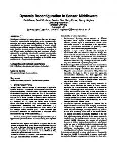
5.3. Gateway: 3SoSM Gateway In a declarative monitoring architecture (see Figure 1), the Gateway is a technical bridge between two environments: it manages interactions and bidirectional communication between the PEMS Query Engine and the WSN. We implemented the 3SoSM principles in a 3SoSM Gateway . It is implemented in Java, and interacts with the SoCQ engine and WSNet. 3SoSM Gateway has two primary modules: the Service Manager, that manages SoCQ services representing available sensor devices (real devices or simulated devices); and the Subscription Manager, that continuously analyses application requirements to generate new sco-patterns for sensor devices when required. In a typical scenario, multiple applications launch continuous queries concerning sensors to the PEMS. The gateway manages required parameterized stream requests and, according to the 3SoSM optimization process, generates optimal sensor configurations. With our integrated prototype, we can execute multiple SoCQ queries that dynamically subscribe to streams provided by WSNet sensor devices. The Gateway transparently optimizes the subscriptions and configures the WSNet sensor devices with sco-patterns. 6. Experiments 6.1. Experimental Setup The simulations are performed using the modified WSNet. We simulate one part of the topology of our physical platform SoCQ4Home deployed in our LIRIS laboratory: 70 sensor devices are located at specific positions over a floor of the building (10m × 60m × 4m). The topology is illustrated in Figure 5. The deployed sensor devices have fixed positions during the simulation and we consider that they have enough energy until the end of the simulation. During the simulation process, the initial energy level of sensor devices is set on purpose to emphasize the lifetime difference between both cases. We adopt known pervasive environment communication protocol Zigbee IEEE 802.15.4, simulated with a UDG propagation model (which is a strong simplification for building environments, as it does not take into account environmental effects), 35m transmission range, and basic radio module states for devices (idle, active, sleep, transmission, reception). Calculation of energy consumption is based on CPU and radio components, adopted from [7]: Edevice = ECP U + Eradio = ECP U + (Esleep + ET X + ERX ), with Ecomponent/mode = 15
10 source sensors relay sensors source−relay sensors sink device
9 8
y−axe (m)
7 6 5 4 3 2 1 0 0
5
10
15
20
25
30
35
40
45
50
55
60
x−axe (m)
Figure 5: Topology of the network (Sensor roles are set based on the Application 1 of the scenario given below).
447 448 449 450 451 452 453 454 455
456 457 458 459 460 461 462 463 464 465 466 467 468 469 470 471 472
Imode .Vdrain . M tmode . This model is a well-known energy consumption calculation model preferred by many researchers. For instance the paper [11] proposes a temperature-aware task mapping approach for the mapping of multiapplication to NoC-based many-core systems by balancing workloads among cores. In our study, we adopt a similar approach to calculate the energy consumption of all devices. We implemented sensor devices for WSNet so that they can reconfigure themselves when they receive a new SCO-Pattern packet, and so that WSNet can monitor their simulated energy consumption while executing sensor actions. 6.2. Experimental Scenario To evaluate our approach, we compare 2 types of architecture: 1) an architecture with basic duty-cycle WSN devices, requiring a static configuration predefined according to scenario requirements; 2) an architecture with 3SoSM approach where WSN devices can be dynamically configured with sco-patterns generated by the 3SoSM Gateway. We design four scenarios: “Temperature of Occupied Rooms”, “Comfort Temperature Range”, “Room occupancy based on CO2 emission” and “Luminosity of rooms”. Each scenario is performed during one day (1440min). Here, we present only one of the performed scenarios due to space limitations. Scenario “Temperature of Occupied Rooms”: One of the features of a typical smart building is monitoring temperatures and occupancy of the environment. Here we suppose that occupancy sensor devices are not always active but has their own duty cycle for detecting the motion. In this scenario, there exists two applications: Application 1: Monitor the temperature of each room with a data acquisition every 15 sec and a latency of 60 sec. 16
473 474 475 476 477 478 479 480 481 482 483 484 485 486 487 488 489 490 491 492 493 494 495 496 497 498 499 500 501 502 503 504 505 506 507 508
Application 2: Monitor temperature of occupied rooms with a data acquisition every 1 sec and a latency of 4 sec. Here, Application 1 requests the temperature from all temperature sensor devices with given application requirements. Application 2 also requests a temperature with a special constraint: it intends to track the temperature only for occupied rooms. For this application requirement, occupancy and temperature sensor devices are needed. For the duty-cycle approach, we adopt a static configuration. In this case, we consider the worst case situation: occupation may be true at any location during the simulation. Based on this constraint, sensor devices are configured with: pacq = 1sec, ptx = 4sec (periodic transmission) In our approach, we propose a dynamic sensor configuration based on the real-time context. To respond to Application 1 and Application 2, sets of SoCQ queries are implemented. For Application 2, from the occupancy stream, we extract the location attribute of the occupied rooms. Then, we list the temperature sensor devices that are located in these rooms and implement a new stream query to subscribe to those temperature services with given application requirements. Since these are continuous queries, once a room is not occupied any more or an unoccupied room become occupied, lists are refreshed and new subscriptions or unsubscriptions are handled in realtime. Then, the 3SoSM Gateway creates schedules for each sensor device and generates sco-patterns to configure sensor devices accordingly. Briefly, Application 1 receives temperature data from relevant devices under every condition. However, Application 2 has a remarkable condition: at least one room should be occupied so that it starts to receive temperature data. Here, there are two subscriptions to the same set of temperature sensor devices located in occupied rooms with different application requirements. During the simulation (one day), energy consumption (in terms of joules) of every sensor are monitored periodically and logged. Besides, three more scenarios are performed. Scenario 2 consists of tracking temperature of each room and requesting more frequently temperatures for rooms that are out of the current comfort temperature range. Scenario 3 is based on the occupancy information retrieved from CO2 emission detected in the room and scenario 4 is related to the luminosity of a classroom. For these scenarios, two applications with different application requirements are executed during a day.
17
Consumed energy of source−relay sensor 2000
with duty cycle
consumed energy (joule)
1800
with 3SoSM
1600 1400 1200 1000 800 600 400 200 0 0
(a) Occupancy of a room (24h).
60
120 180 240 300 360 420 480 540 600 660 720 780 840 900 960 1020 1080 1140 1200 1260 1320 1380 1440 time (min)
(b) Average consumed energy (in joule) of a source-relay device (24h). Upper line for duty cycling, lower line for 3SoSM.
Figure 6: Occupancy information and Energy consumption of the most significant device type: source-relay device with duty cycling and with our approach 3SoSM.
509
510 511 512 513 514 515 516 517 518 519 520 521 522 523 524 525 526 527 528 529 530 531 532
7. Results and Discussion During the experiments, energy consumption of each sensor device is monitored. Figure 6 shows the average energy consumption of source-relay devices. As a remark, the sink device is not considered as a part of this energy consumption calculation. Here, we present the results of the first scenario in detail for one day (1440min). Firstly, the room is not occupied (see Figure 6a), hence the 3SoSM Gateway creates a schedule and configures the relevant sensor devices according to that situation. Once the room is detected as occupied, the 3SoSM Gateway re-creates a schedule and re-configures the relevant sensor devices. In fact, the 3SoSM Gateway creates a new schedule and configures sensor devices to adapt to each contextual change in the environment. Thus, adapting the system to the dynamic context avoids sensor devices from unnecessary data acquisitions and transmissions. Hence, the economy of energy can be achieved with this context-awareness, as shown in Figure 6b. Evolution of the energy consumption for the WSN can be observed with heat maps as well. Figure 7 represents the heat map of the network based on the energy level of the sensor devices at the end of the simulation (t=24h), with duty-cycle method (Figure 7a) and with our 3SoSM approach (Figure 7b), according to the given topology (see Figure 5). With the settings of the scenario “Temperature of Occupied Rooms”, we observe that our approach 3SoSM enhances the lifetime of the sensor devices significantly. For source-relay sensor devices, with given application requirements, 3SoSM extends their lifetime by 8.9 times on average. 18
(a) Heatmap of remaining energy at t=24h with duty cycle.
(b) Heatmap of remaining energy at t=24h with 3SoSM.
Figure 7: Heatmap of remaining energy with duty-cycle and with 3SoSM. Table 2: Summary of the Experiments. Scenarios
Temperature of Occupied Rooms Comfort Temperature Range Room Occupancy based on CO2 Luminosity of Rooms
533 534 535 536 537 538 539 540 541 542 543 544 545 546 547 548 549 550 551 552
Application Parameters Application 1 Application 2 acq p λ pacq λ (sec) (sec) (sec) (sec) 15
60
1
4
20
60
10
30
120
15
30
100
20
Lifetime (day) Duty cycling
3SoSM Approach
15
146
20
9
90
60
11
95
80
10
34
By applying our approach to given application requirements, we optimize the energy consumption and reduce the unnecessary communication cost. Obtained results on energy saving and lifetime extension depend on the application requirements and the context of the application such as temperature and presence. For the current settings, the most unfavorable case is the situation where every room is occupied during the entire simulation time. Even in that case, 3SoSM achieves a concrete energy enhancement since the regular duty-cycle approach does not benefit from latency requirement which provides a tangible energy saving by allowing grouped transmission of multiple acquired data. Besides, the details of the other performed scenarios are summarized in Table 2 for each scenario, application requirements are given and the average lifetime of source-relay sensor devices are presented. We also obtain a significant energy enhancement and a lifetime extension by avoiding unnecessary communication. However, balancing the workload of the network over the sensor devices like [11] introduces, advanced clustering mechanism like [5] presents, may further enhance the network lifetime and the obtained results. [5] presents that with a clustering mechanism and selecting cluster headers in an optimal way may extend the lifetime of the network better than any other cluster 19
557
based networks. With more populated topologies and with massive subscription requests, a discussion about the optimization process appears: in which conditions our approach may fail to find the optimal slots on the schedules (since a slot is reserved for a single device)? In these cases, granularity should be decreased to have enough slots for the sensor devices.
558
8. Related Works
553 554 555 556
559 560 561 562 563
564 565 566 567 568 569
570 571 572 573 574 575 576 577 578 579 580 581 582 583 584 585 586 587
WSN are related to several different research domains such as pervasive environment, and smart building systems. In this paper, we give a brief summary of the following research areas that are concerned by our study: energy issues in WSN, sensor network query processing (SNQP), sensor-based Smart Building Management Systems (SBMS). Energy Issue in WSN. Wireless devices bring important constraints such as limited battery lifetime. [12] classifies the existing studies on energy consumption of wireless sensor devices into 3 subgroups: duty-cycle, data-driven and mobility-based approaches. Our sensor configuration based subscription management approach benefits from scheduled rendezvous of duty-cycling and adaptive sampling/transmission of data-driven approaches. Sensor Network Query Processing. The main functionality of Sensor Network Query Processors (SNQP) is to handle continuous queries and sensor data streams [13]. [14, 15] propose an adaptive in-network aggregation operator ADAGA for query processing on sensor devices in order to filter and reduce the volume of sensor data. The main functionality of ADAGA is to regulate/adjust sensor activities based on energy levels and memory usage of sensor devices. As we propose in our own study, ADAGA is also capable of processing query parameters but the study does not tackle multi-application context and multi-modality of wireless devices as proposed in our own work. We use the Service-oriented Continuous Query (SoCQ) Engine [1] to manage sensor data streams. SoCQ has a strong advantage from its rivals (especially SNEE [8]) as it supports multi-application contexts. However, it supports neither energy-awareness nor real-time sensor configuration. Our approach provides these features and improvement to the SoCQ Engine. Among available technologies for SNQP, [8] is the closest study to our approach. This study deal with the conflict between the quality of service and sensor acquisition/transmission settings. Authors propose an optimization of application requests and the generation of a query execution plan. Generated 20
588 589 590 591 592
593 594 595 596 597 598 599 600 601 602 603 604 605 606 607 608 609 610 611 612 613 614 615 616 617 618 619 620 621 622 623 624
execution plan provides a global view of the network and a schedule that shows when to execute a sensor action (sleep, listen, receive/send a packet). In terms of sensor scheduling and parametrization of a query, this approach is highly close to ours. Still, query execution plan covers a single query with a single expectation. Sensor-based Building Systems. Some other studies focus on the design and data management aspects as well. Most of those approaches are proposed for a specific application and adopt a static configuration for sensor devices. Sensor-actuator based environment management systems are also studied in this area. [16] mentions that sensor-actuator interactions has a significant effect on efficient building monitoring. Moreover, the study points out that estimation of our daily activities has a crucial role on managing heterogeneous sensor devices in the environment and provides energy saving and longer lifespans. [5] indicates that clustering and energy efficiency have been considered in wide area of WSN applications and propose a mechanism in which clusters are dynamically built up by neighbor nodes, to save energy and prolong the network lifetime. [17, 18] are the closest studies to ours. [17] presents intelligent building architecture based on a self-adapting intelligent gateway. [18] presents selfadapting algorithms for context-aware systems. These studies propose dynamic system management while processing user preferences. However, these studies are bounded by predefined building applications and the relation between application requirements and sensor configuration is not established. Besides, these approaches do not benefit from the potential reconfiguration of acquisition and transmission frequencies: sensor configuration stays static during the system lifetime. Moreover, energy consumption within the WSN is not considered as a major issue. [19] is also close to our approach. Author implicates event-triggered dynamic sensor configuration. The study proposes a ZigBee-based intelligent self-adjusting sensor platform (ZiSAS) that can autonomously reconfigure middleware, network topology, sensor density, and sensing rate based on the environmental situation. However, unlike our proposition, user preferences, application requirements, query mechanism or data stream processing are not handled. Overview of most known existing studies on Smart Building applications is summarized in Table 3. For the categorization of these studies, we benefit from the key functionalities of a Smart Building Management System 21
Table 3: Overview of most known existing studies on Smart Building applications. Study Doukas et al. [21] Chen et al. [22] Byun et al. [19] Xiang et al. [23] Rutishauser et al. [24] Servigne et al. [25] Mamidi et al. [26] Kailas et al. [27] Agarwal et al. [28] Preisel et al. [29] Schor et al. [30] Li et al. [31] 3SoSM
MultiApp
Dynamic User Config.
– – – – – – – – – – – – √
– – – – – – – – – – – – √
ContextAwareness √ √ √ √ √ – √ √ √ – √ √ √
RealTime Sensor Config. – – √
EnergyAware Monitoring – – √
– – – – – – – – – √
– – – – – – √ √ √ √
Query Engine – – – √ √ – – – – – – – √
Experimentation Real Testbed Simulation Real Testbed Real Testbed Real Testbed Real Testbed Real Testbed Real Testbed Real Testbed Real Testbed Real Testbed Real testbed Real Testbed and Simulation
642
(SBMS) [20]. The last line of the table is allocated for our approach 3SoSM. Our research motivation is that the existing approaches are mostly WSN-level techniques that do not tackle real-time dynamic interactions between application continuous queries and the physical environment, in a multi-application context where sensor devices are multi-modal and requirements are dynamic. Hence, this lack creates a gap between the computing environment and the physical environment, that can be both managed by pervasive applications. To address this gap and propose a clear solution for multi-application monitoring systems, we design a sustainable multi-application monitoring system architecture for pervasive environments that collects application requirements for sensor data streams and optimizes them into sensor configurations. We propose energy-aware dynamic sensor device re-configuration (as a result of an optimization process) to lower energy consumption while fulfilling real-time application requirements. Compared to existing studies, our approach 3SoSM provides a multi-application mechanism and allows dynamicity for user configurations and network-aware sensor management while optimizing the sensor communication for enhancing energy consumption by real-time sensor configuration.
643
9. Conclusion
625 626 627 628 629 630 631 632 633 634 635 636 637 638 639 640 641
644 645 646 647 648
In this paper, we focus on one of the major challenges of pervasive monitoring systems like smart buildings: how to optimize/reduce the energy consumption of the monitoring architecture itself while managing sensor data streams. Existing studies do not tackle the energy consumption of the monitoring system and commonly adopt static configurations for sensor devices. 22
664
Since application requirements are dynamic with the context, a dynamic sensor configuration can be a suitable option to solve this problem. We introduce a sustainable declarative monitoring architecture where we adopt the PEMS principles to separate application development and optimization of device interactions. We present our approach 3SoSM that is based on a WSN scheduling mechanism for sensor actions. We propose an optimization algorithm to find the optimal communication time slots. As an outcome, an optimized schedule generates sco-patterns to configure each device. We introduce our implementation 3SoSM Gateway that supports the optimization process for multiple parameterized subscriptions from dynamic application requirements. Our approach is validated by the experiments using the SoCQ Engine and a modified WSNet simulator. Moreover, our approach gives opportunities to use real testbed data and simulation data which is not so common in the pervasive environment research domain. Smart building applications are our target application, however, this approach can be applicable to other data-centric pervasive environments as well [2].
665
Conflict of Interest
649 650 651 652 653 654 655 656 657 658 659 660 661 662 663
667
The authors declare that there is no conflict of interests regarding the publication of this paper.
668
References
666
669 670
671 672 673
674 675 676 677
678 679 680
[1] Y. Gripay, F. Laforest, J.-M. Petit, Socq: A framework for pervasive environments, in: ISPAN’09, IEEE, 2009, pp. 154–159. [2] S. Surdu, Y. Gripay, V.-M. Scuturici, J.-M. Petit, P-bench: benchmarking in datacentric pervasive application development, in: Transactions on Large-Scale Data-and Knowledge-Centered Systems XI, Springer, 2013, pp. 51–75. [3] S. Servigne, Y. Gripay, O. Pinarer, J. Samuel, A. Ozgovde, J. Jay, Heterogeneous sensor data exploration and sustainable declarative monitoring architecture: Application to smart building, ISPRS Ann. Photogramm. Remote Sens. Spatial Inf. Sci IV-4/W1 (2016) 97–104. [4] C. Perera, A. Zaslavsky, M. Compton, P. Christen, D. Georgakopoulos, Semanticdriven configuration of internet of things middleware, in: SKG’13, IEEE, 2013, pp. 66–73.
23
681 682 683 684
685 686 687
688 689 690
691 692
693 694
[5] P. G. V. Naranjo, M. Shojafar, H. Mostafaei, Z. Pooranian, E. Baccarelli, P-sep: a prolong stable election routing algorithm for energy-limited heterogeneous fogsupported wireless sensor networks, The Journal of Supercomputing 73 (2) (2017) 733–755. [6] O. Pinarer, Y. Gripay, S. Servigne, A. Ozgovde, Energy enhancement of multiapplication monitoring systems for smart buildings, in: International Conference on Advanced Information Systems Engineering, Springer, 2016, pp. 131–142. [7] O. Pinarer, A. Ozgovde, Improving the energy efficiency of wearable computing units using on sensor fifo memory, International Journal of e-Education, e-Business, eManagement and e-Learning 5 (2) (2015) 105. [8] I. Galpin, A. A. Fernandes, N. W. Paton, Qos-aware optimization of sensor network queries, The VLDB Journal 22 (4) (2013) 495–517. [9] I. Cardei, M. Cardei, Energy-efficient connected-coverage in wireless sensor networks, International Journal of Sensor Networks 3 (3) (2008) 201–210.
695
[10] Wsnet / worldsens simulator, http://wsnet.gforge.inria.fr/.
696
[11] S. Cao, Z. Salcic, Z. Li, S. Wei, Y. Ding, Temperature-aware multi-application mapping on network-on-chip based many-core systems, Microprocessors and Microsystems 46 (2016) 149–160.
697 698
699 700
701 702
703 704 705
706 707 708
709 710 711
712 713 714
[12] G. Anastasi, M. Conti, M. Di Francesco, A. Passarella, Energy conservation in wireless sensor networks: A survey, Ad hoc networks 7 (3) (2009) 537–568. [13] F. Jabeen, S. Nawaz, In-network wireless sensor network query processors: State of the art, challenges and future directions, Information Fusion 25 (2015) 1–15. [14] A. Brayner, A. L. Coelho, K. Marinho, R. Holanda, W. Castro, On query processing in wireless sensor networks using classes of quality of queries, Information Fusion 15 (2014) 44–55. [15] A. Brayner, A. Lopes, D. Meira, R. Vasconcelos, R. Menezes, An adaptive in-network aggregation operator for query processing in wsn, Journal of Systems and Software 81 (3) (2008) 328–342. [16] F. Viani, F. Robol, A. Polo, P. Rocca, G. Oliveri, A. Massa, Wireless architectures for heterogeneous sensing in smart home applications: Concepts and real implementation, Proceedings of the IEEE 101 (11) (2013) 2381–2396. [17] J. Byun, S. Park, Development of a self-adapting intelligent system for building energy saving and context-aware smart services, IEEE Transactions on Consumer Electronics 57 (1) (2011) 90–98.
24
715 716 717
718 719 720
721 722
723 724 725
726 727
728 729
730 731 732
733 734 735
736 737 738
739 740 741
742 743 744
745 746
747 748
[18] T. Cioara, I. Anghel, I. Salomie, M. Dinsoreanu, G. Copil, D. Moldovan, A selfadapting algorithm for context aware systems, in: RoEduNet’10, IEEE, 2010, pp. 374–379. [19] J. Byun, B. Jeon, J. Noh, Y. Kim, S. Park, An intelligent self-adjusting sensor for smart home services based on zigbee communications, IEEE Transactions on Consumer Electronics 58 (3) (2012) 794–802. [20] T. A. Nguyen, M. Aiello, Energy intelligent buildings based on user activity: A survey, Energy and buildings 56 (2013) 244–257. [21] H. Doukas, K. D. Patlitzianas, K. Iatropoulos, J. Psarras, Intelligent building energy management system using rule sets, Journal of Building and Environment 42 (10) (2007) 3562–3569. [22] H. Chen, P. Chou, S. Duri, H. Lei, J. Reason, The design and implementation of a smart building control system, in: ICEBE’09, Citeseer, 2009. [23] S. Xiang, W. Wu, K.-L. Tan, Optimizing multiple data acquisition queries in sparse mobile sensor networks, in: MDM’12, IEEE, 2012, pp. 137–146. [24] U. Rutishauser, J. Joller, R. Douglas, Control and learning of ambience by an intelligent building, IEEE Transactions on Systems, Man and Cybernetics, Part A: Systems and Humans 35 (1) (2005) 121–132. [25] S. Servigne, Y. Gripay, J.-M. Deleuil, C. Nguyen, J. Jay, O. Cavadenti, R. Mebrouk, Data science approach for a cross-disciplinary understanding of urban phenomena: Application to energy efficiency of buildings, Procedia Engineering 115 (2015) 45–52. [26] S. Mamidi, Y.-H. Chang, R. Maheswaran, Improving building energy efficiency with a network of sensing, learning and prediction agents, in: Proceedings of the 11th AAMAS, Vol. 1, IFAAMAS’12, 2012, pp. 45–52. [27] A. Kailas, V. Cecchi, A. Mukherjee, A survey of communications and networking technologies for energy management in buildings and home automation, Journal of Computer Networks and Communications 2012. [28] Y. Agarwal, B. Balaji, R. Gupta, J. Lyles, M. Wei, T. Weng, Occupancy-driven energy management for smart building automation, Journal of Power 50 (100) (2010) 150. [29] M. Preisel, A. Diaz, W. Wimmer, Energy consumption of smart meters, Journal of Information and Communication Technologies (2013) 37. [30] L. Schor, P. Sommer, R. Wattenhofer, Towards a zero-configuration wireless sensor network architecture for smart buildings, in: BuildSys’09, ACM, 2009, pp. 31–36.
25
749 750 751
[31] C. Li, F. Meggers, M. Li, J. Sundaravaradan, F. Xue, H. Lim, A. Schlueter, Bubblesense: wireless sensor network based intelligent building monitoring, Proceedings of the ICT4S’13 (2013) 159–166.
26