... Biomechanical Models. Philip Pratt, Danail Stoyanov, ..... Lerotic, M., Lee, S.L., Keegan, J., Yang, G.Z.: Image constrained finite element modelling for real-time ...
Dynamic Guidance for Robotic Surgery Using Image-Constrained Biomechanical Models Philip Pratt, Danail Stoyanov, Marco Visentini-Scarzanella, and Guang-Zhong Yang Institute of Biomedical Engineering Imperial College of Science, Technology and Medicine, London SW7 2AZ, UK {p.pratt,danail.stoyanov,mv402,g.z.yang}@imperial.ac.uk Abstract. The use of physically-based models combined with image constraints for intraoperative guidance is important for surgical procedures that involve large-scale tissue deformation. A biomechanical model of tissue deformation is described in which surface positional constraints and internally generated forces are derived from endoscopic images and preoperative 4D CT data, respectively. Considering cardiac motion, a novel technique is presented which minimises the average registration error over one or more complete cycles. Features tracked in the stereo video stream provide surface constraints, and an inverse finite element simulation is presented which allows internal forces to be recovered from known preoperative displacements. The accuracy of surface texture, segmented mesh and volumetrically rendered overlays is evaluated with detailed phantom experiments. Results indicate that by combining preoperative and intraoperative images in this manner, accurate intraoperative tissue deformation modelling can be achieved.
1
Introduction
Image guidance plays an important role in the deployment of minimally invasive surgery for complex procedures. It needs to be capable of seamlessly integrating preoperative and intraoperative images of dynamic anatomical structure, thereby enhancing the surgeon’s view with detailed navigational cues, attaining a high level of spatiotemporal accuracy. To this end, physically-based modelling has attracted significant interest since during surgery, the exposed tissue surface for co-registration with preoperative data is typically small, and the approach allows for the effective incorporation of biomechanical constraints. The primary target application for this work is vessel identification and harvest prior to TECAB, but it is also applicable to image-guided liver resection and partial nephrectomy for the removal of metastases, in the presence of respiratory motion. Dynamic guidance systems present significant technological challenges, but several notable advances have already been made. Sun et al. [1] describe a method for modelling tissue retraction during image-guided neurosurgery. A poroelastic brain model is driven by the stereoscopically-measured motion of a retractor to produce a full volume displacement field, which is used to update the preoperative MR images. Szpala et al. [2] derive a sequence of linear free-form T. Jiang et al. (Eds.): MICCAI 2010, Part I, LNCS 6361, pp. 77–85, 2010. c Springer-Verlag Berlin Heidelberg 2010 �
78
P. Pratt et al.
deformations from preoperative CT images, which are applied subsequently to a high-quality heart mesh model generated at end-diastole. Temporal synchronisation is driven by an electrocardographic trigger signal, whereas spatial registration of optically-tracked phantom casing and endoscope coordinate systems is achieved using linear least squares error minimisation. Figl et al. [3] build a 4D B-spline motion model of the beating heart from multiple coronary CT phases. Temporal alignment with endoscopic video is obtained using an ECG signal. Two methods are proposed for spatial alignment: the first considers model registration to 3D feature positions tracked in the endoscopic feed, and the second employs photo-consistency as a similarity metric. Su et al. [4] propose a near real-time 3D-CT to stereo endoscopic video registration method for robot-assisted partial nephrectomy. Selected features on the kidney surface are tracked from one video frame to the next, and are registered to a preoperatively-generated model of the anatomy using a modified iterative closest point technique. Lerotic et al. [5] introduce an image-constrained linear finite element simulation of the lung parenchyma capable of real-time performance. A model for the motion of points on the lung surface, incorporating amplitude, period and phase parameters, is fitted to landmarks acquired from preoperative MR scan data at full inhale and exhale. The motion model parameters are optimised using golden section search, which is then used to provide surface constraints for the finite element simulation which, in turn, determines the overlay deformation. However, existing methods fail to combine preoperative and intraoperative images in a way that is simultaneously accurate for surface texture, segmented mesh and volumetrically rendered overlay regimes. Furthermore, initial spatiotemporal registrations typically do not exploit positional data acquired over an extended period of time. This paper proposes a method which achieves these goals, and promises to enhance the surgeon’s sensory experience, reduced initially as a direct consequence of minimally invasive robotic access. The method is also applicable to the wider context that includes preoperative rehearsal and intraoperative simulation of tool-tissue interaction, where the surface constraints are derived or enhanced, respectively, by known instrument positions. The method has also been implemented to exploit GPU acceleration and is capable of realtime operation, thus facilitating practical clinical use.
2 2.1
Material and Methods Stereo Feature Tracking
In this study, the exposed tissue surface geometry is captured by the da Vinci stereo endoscope, with camera calibration following Zhang [6]. The motion tracking technique described by Stoyanov et al. [7] is used to recover tissue surface motion. Robust performance is ensured by using a combination of landmarks,
Dynamic Guidance for Robotic Surgery
79
including maximally stable extremal regions (MSER) and traditional gradientbased image features. 2.2
Spatiotemporal Registration
The problem is formulated as a least-squares distance optimisation problem over projected 3D fiducial positions segmented from scan data and corresponding points recovered from the stereo video sequence. Rather than perform the optimisation at a single point in time, squares of the residual distances are summed over one or more complete phases of cardiac motion. It then remains to find the minimal overall sum by varying the initially unknown temporal phase difference between the first 4D scan phase and the first video frame. Symbolically, if fiducials are indexed by i and video frames by j, and λ is the temporal phase shift, and θx , θy , θz , tx , ty , tz are the rotations and translations, respectively, that parameterise the transformation R from the scan coordinate system to the camera coordinate system, then the quantity to be minimised is � �� 2 2 � pL (R si (τj + λ)) − tL (τj ) � + � pR (R si (τj + λ)) − tR (τj ) � (1) i,j
where pL and pR are the left and right 2D vector-valued projection functions, including lens distortion, determined by the stereo camera calibration stage. The si represent the 3D fiducials coordinates derived from scan data, and the tL and tR are the 2D coordinates of the corresponding left and right points in the video sequence. They are evaluated at the discrete points in time τj corresponding to each video frame. Scan phases and video frames are assumed to extend through time in a cyclic manner, and linear interpolation in time is used to evaluate fiducials coordinates lying between scan phases. 2.3
Finite Element Simulation
In previous work, Miller et al. [8] describe the total Lagrangian explicit dynamics (TLED) algorithm. An efficient GPU implementation is used here to model deformation of the heart resulting from surface positional constraints and internal forces implied by the original 4D scan motion. In contrast to the updated Lagrangian formulation, this method expresses stress and strain measures in terms of the reference configuration. As such, many quantities can be either completely or partially precomputed, and together with an explicit integration scheme, the algorithm enables nonlinear finite element simulation using relatively complex meshes at interactive rates. Using the notation of Bathe [9], the equations of motion for a mesh comprising N nodes, written in semi-discrete form and expressed in terms of the �� � displacements U = u0 u1 . . . u3N −1 from the initial configuration, are ¨ + C tU ˙ +t F = tR M tU 0
(2)
80
P. Pratt et al.
˙ and t U ¨ are the velocity and acceleration vectors, respectively, and M is where t U the constant lumped mass matrix. The damping matrix C = αM is assumed to be proportional to the mass matrix, where α is the Rayleigh damping coefficient. The vectors t0 F and t R represent the nodal reaction forces equivalent to element stresses, and externally applied forces, respectively. Subsequent time discretisation, with step size Δt, and application of an explicit central difference integration scheme gives the following update rule � � 2 Δt t 2 αΔt t+Δt ( R −t0F) + 2 tU + ( − 1) t−ΔtU U= (3) 2 + αΔt M 2 The constitutive law employed is that of a compressible neo-Hookean material. The following constants are used in the simulation: Young’s modulus E = 3.0E+ 3 03 Pa; Poisson’s ratio ν = 0.45; material density ρ = 1.0E + 03 kg/m ; and mass damping coefficient α = 7.5E+01. In this instance, the equations of motion are integrated using the conservatively small time step of Δt = 0.0002 seconds. 2.4
Mesh Generation and Temporal Smoothing
The heart phantom is segmented from the initial scan phase using edge-based snakes, as made available in the ITK-SNAP tool (see Yushkevich et al. [10]). Additional manual segmentation follows to make the simplification whereby the phantom is assumed to have a solid spherical topology. Subsequently, the highresolution surface mesh, generated at the voxel level, is further simplified using quadric edge collapse decimation to a resolution suitable for interactive finite element simulation. Finally, tetrahedralisation is applied using Gmsh [11], and the resulting mesh is optimised for element quality. The Image Registration Toolkit (see Rueckert et al. [12] and Schnabel et al. [13]) is used to determine the sequence of 3D tensor product B-spline deformations which maps the initial phase on to each subsequent phase in turn. These deformations are applied to the initial tetrahedral mesh to create a sequence of vertex displacements at discrete points in time. Finally, cyclic 1D B-splines over the time dimension are fitted through each vertex, both to smooth the motion implied from the scan sequence and to provide a means for obtaining phantom geometry at arbitrary positions in the cardiac cycle. 2.5
Application of Surface Constraints
Once a spatial and temporal registration has been established, tracked features in the initial video frame are associated with interpolated mesh node positions at the corresponding point in time. For each feature, the nearest node is identified in the collection of mesh surface nodes. These associations are maintained throughout the duration of the simulation. Each such node will have one or more feature associations, and as the latter displace over time, the average of their displacements is assigned to the node displacement, thereby enforcing a dynamic positional constraint. Typically, the simulation time step is smaller than the period of each video frame, so linear interpolation is applied to all positional
Dynamic Guidance for Robotic Surgery
81
constraints over the duration of the frame. In addition, static regions in the original scan, comprising the heart phantom mounting, are segmented and meshed, and then used to locate surface mesh nodes that are to be held fixed with zero displacement during the simulation. 2.6
Force Recovery and Resolution
The method of force recovery and resolution described by Pratt [14] is used to incorporate cyclic organ motion derived from 4D scan data. Firstly, the forward update rule given by equation 3 is inverted, such that the externally applied forces can be expressed in terms of known displacements, as follows � � M αΔt αΔt t+Δt t t t−Δt ) − 1) R= U − 2 U − ( U +t0F (4) (1 + Δt2 2 2 Subsequently, in the absence of positional constraints, if the recovered forces were to be applied at the appropriate instants during forward simulation, then the original motion would result by construction. In the presence of positional constraints, however, the recovered forces must be resolved from the global coordinate systems into systems local to each mesh element. At a given node, the recovered force r at that node is shared equally amongst the M elements to which it belongs. Symbolically, the contribution from each node in each element is written barycentrically as the weighted sum of adjacent element edge vectors b0 , b1 and b2 , as follows 1 r = w0 b0 + w1 b1 + w2 b2 M
(5)
By expressing these forces in terms of local geometry in this manner, they are made to act in the directions consistent with external constraint-induced deformation. In practice, the inverse and forward simulations are performed simultaneously to avoid storage of intermediate results. Forces are always recovered from the original displacements, and are expressed in terms of the original geometry. The forward simulation is then propagated using forces implied by the current geometry. 2.7
Overlay Deformation
As the current geometry is updated in time, the resulting new node positions are used to deform high-resolution overlay information in one of three ways. Firstly, high-resolution meshes segmented and built from the original CT scan data are embedded in the finite element mesh by associating each vertex in the former with its containing element, and precomputing their barycentric coordinates. Vertex update is then performed by transforming back to the global coordinate system in the context of the current geometry. Secondly, volumetrically rendered scan data is deformed by slicing each tetrahedral element individually, from back to front in planes perpendicular to the z-axis, and alpha-compositing
82
P. Pratt et al.
the results. The resulting overlays are presented using the Inverse Realism technique described by Lerotic et al. [15]. Finally, preoperatively determined surface landmarks and annotations are rendered as textures covering the finite element mesh, and are alpha-blended directly with the output video feed. 2.8
Validation
In order to assess 2D overlay accuracy when positional surface constraints are combined with recovered and resolved internal forces, the results of manual frame-by-frame video feature tracking are compared, considering the left stereo channel, with the positions of equivalent textured features rendered using the deforming geometry. In addition to the combined case, results are also evaluated for simulations where surface constraints and internal forces are applied individually. A similar approach is adopted for 3D validation, where simulation results are compared over multiple cardiac cycles against the spatial locations of volumetric features identified in the original scan data.
3
Results and Discussion
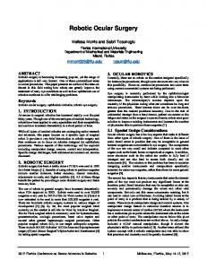
For quantitative assessment of the proposed method, detailed phantom experiments were conducted using a Chamberlain Group CABG beating heart phantom. In the first instance, the phantom was scanned at 90 bpm with a Philips 64-slice CT scanner, producing 20 uniformly spaced phases. Fiducial markers embedded in the outer layer of the phantom were manually segmented in each of the phases in order to recover the sequence of spatial locations. Using the corresponding left and right 2D stereo locations of five such fiducials in the captured da Vinci endoscope video stream, the optimal spatiotemporal registration produced by the procedure described in section 2.2 had average left and right errors of 0.4712 mm and 0.4667 mm, respectively. The output frames in figure 1 shows an original image captured from the da Vinci endoscope, the same frame blended with the spatiotemporally registered FEM mesh, and surface texture and internal structure overlay regimes. The results shown on the left of table 1 compare 2D surface overlay accuracies against a typical feature manually tracked in the left video stream, considering the surface-only, force-only (i.e. volume) and combined constraint modes. Average and maximum errors, and root-mean-square deviations are determined over
Fig. 1. Single da Vinci endoscope video frame, registered FEM mesh and overlays
Dynamic Guidance for Robotic Surgery
83
Table 1. Projected surface texture and internal structure overlay errors surface overlay internal overlay error (mm) surface volume combined surface volume combined average 0.33 0.69 0.36 1.05 0.16 0.83 maximum 0.64 1.40 0.68 2.16 0.32 1.75 RMSD 0.36 0.80 0.40 1.21 0.18 0.92
Fig. 2. Overlay errors for surface texture (2D) and internal structure (3D) regimes
Table 2. Relative analysis of fiducial deformation and overlay errors error (mm) fiducial #1 fiducial #2 fiducial #3 fiducial #4 fiducial #5 average deformed 0.23 0.31 0.20 0.23 0.23 0.24 volume 0.25 0.30 0.20 0.23 0.33 0.26
a period covering three complete cardiac cycles. It can be seen that the application of surface constraints alone gives rise to the most accurate overlay, but that the inclusion of recovered and resolved forces degrades the performance only marginally. The left graph in figure 2 illustrates the manner in which overlay accuracy changes during this period. Similarly, the results shown on the right of table 1 compare the location of a typical deforming feature identified in the original CT scan against the location of the same feature produced by barycentric interpolation of the point embedded in the FEM tetrahedral mesh, undergoing deformation implied by each of the constraint modes. As expect, simulation using only recovered and resolved forces produces the most accurate overlay. However, the combined constraint mode performs better than the application of surface constraints alone. The right graph in figure 2 illustrates changes in overlay accuracy during three consecutive cardiac cycles. Thus it can be seen that the combined constraint mode offers a good compromise over the surface-only and internal force-only alternatives, and results in a level of accuracy acceptable for dynamic guidance during interventions.
84
P. Pratt et al.
In-depth analysis of the different factors affecting the total overlay error reveals that a significant proportion can be attributed to the recovery of 3D Bspline deformations, as described in section 2.4. Table 2 compares the positions of fiducials manually segmented from each scan phase against the positions resulting from 3D B-spline deformation of the first phase, and also the full simulation results using the force-only constraint mode. Again, results are averaged over three complete cardiac cycles. They differ marginally, indicating that temporal smoothing and the simulation itself contribute relatively little to the total error.
4
Conclusion
This work proposes a new modelling framework for fusing preoperative tomographic and intraoperative endoscopic data in a dynamic environment, such that accurate overlays can be rendered in both surface texture and internal structure regimes. A physically-based, inverse finite element simulation transforms preoperative motion into a representation where it can be readily combined with tissue surface constraints. Furthermore, the method is cast in a setting that fulfils the key requirement of real-time operation, necessary to guarantee minimal latency in the surgeon’s visual-motor feedback loop. Finally, a novel spatiotemporal registration technique is described which minimises errors over one or more complete cardiac cycles.
References 1. Sun, H., Kennedy, F.E., Carlson, E.J., Hartov, A., Roberts, D.W., Paulsen, K.D.: Modeling of brain tissue retraction using intraoperative data. In: Barillot, C., Haynor, D.R., Hellier, P. (eds.) MICCAI 2004, Part II. LNCS, vol. 3217, pp. 225– 233. Springer, Heidelberg (2004) 2. Szpala, S., Wierzbicki, M., Guiraudon, G., Peters, T.M.: Real-time fusion of endoscopic views with dynamic 3-D cardiac images: A phantom study. IEEE Transactions on Medical Imaging 24(9), 1207–1215 (2005) 3. Figl, M., Rueckert, D., Hawkes, D., Casula, R., Hu, M., Pedro, O., Zhang, D.P., Penney, G., Bello, F., Edwards, P.: Image guidance for robotic minimally invasive coronary artery bypass. In: Dohi, T., Sakuma, I., Liao, H. (eds.) MIAR 2008. LNCS, vol. 5128, pp. 202–209. Springer, Heidelberg (2008) 4. Su, L.M., Vagvolgyi, B.P., Agarwal, R., Reiley, C.E., Taylor, R.H., Hager, G.D.: Augmented reality during robot-assisted laparoscopic partial nephrectomy: Toward real-time 3D-CT to stereoscopic video registration. Urology 73(4), 896–900 (2009) 5. Lerotic, M., Lee, S.L., Keegan, J., Yang, G.Z.: Image constrained finite element modelling for real-time surgical simulation and guidance. In: Proceedings of the IEEE International Symposium on Biomedical Imaging, pp. 1063–1066 (2009) 6. Zhang, Z.: A flexible new technique for camera calibration. IEEE Transactions on Pattern Analysis and Machine Intelligence 22(11), 1330–1334 (2000) 7. Stoyanov, D., Mylonas, G.P., Deligianni, F., Darzi, A., Yang, G.Z.: Soft-tissue motion tracking and structure estimation for robotic assisted MIS procedures. In: Duncan, J.S., Gerig, G. (eds.) MICCAI 2005, Part II. LNCS, vol. 3750, pp. 139– 146. Springer, Heidelberg (2005)
Dynamic Guidance for Robotic Surgery
85
8. Miller, K., Joldes, G., Lance, D., Wittek, A.: Total lagrangian explicit dynamics finite element algorithm for computing soft tissue deformation. Communications in Numerical Methods in Engineering 23, 121–134 (2007) 9. Bathe, K.J.: Finite Element Procedures. Prentice-Hall, Inc., Englewood Cliffs (1996) 10. Yushkevich, P.A., Piven, J., Cody Hazlett, H., Gimpel Smith, R., Ho, S., Gee, J.C., Gerig, G.: User-guided 3D active contour segmentation of anatomical structures. Neuroimage 31(3), 1116–1128 (2006) 11. Geuzaine, C., Remacle, J.F.: Gmsh: a three-dimensional finite element mesh generator with built-in pre- and post-processing facilities. International Journal for Numerical Methods in Engineering 79(11), 1309–1331 (2009) 12. Rueckert, D., Sonoda, L.I., Hayes, C., Hill, D.L.G., Leach, M.O., Hawkes, D.J.: Non-rigid registration using free-form deformations: Application to breast MR images. IEEE Transactions on Medical Imaging 18(8), 712–721 (1999) 13. Schnabel, J.A., Rueckert, D., Quist, M., Blackall, J.M., Castellano-Smith, A.D., Hartkens, T., Penney, G.P., Hall, W.A., Liu, H., Truwit, C.L., Gerritsen, F.A., Hill, D.L.G., Hawkes, D.J.: A generic framework for non-rigid registration based on non-uniform multi-level free-form deformations. In: Niessen, W.J., Viergever, M.A. (eds.) MICCAI 2001. LNCS, vol. 2208, pp. 573–581. Springer, Heidelberg (2001) 14. Pratt, P.: Image guidance and surgery simulation using inverse nonlinear finite element methods. In: Bello, F., Edwards, E. (eds.) ISBMS 2008. LNCS, vol. 5104, pp. 185–190. Springer, Heidelberg (2008) 15. Lerotic, M., Chung, A.J., Mylonas, G., Yang, G.Z.: pq-space based nonphotorealistic rendering for augmented reality. In: Ayache, N., Ourselin, S., Maeder, A. (eds.) MICCAI 2007, Part II. LNCS, vol. 4792, pp. 102–109. Springer, Heidelberg (2007)