Hindawi Publishing Corporation International Journal of Manufacturing Engineering Volume 2016, Article ID 8697453, 14 pages http://dx.doi.org/10.1155/2016/8697453
Research Article Dynamic Interaction between Machine, Tool, and Substrate in Bobbin Friction Stir Welding Mohammad K. Sued1,2 and Dirk J. Pons1 1
Faculty of Manufacturing Engineering, Universiti Teknikal Malaysia Melaka, Hang Tuah Jaya, 76100 Durian Tunggal, Melaka, Malaysia 2 Mechanical Engineering, University of Canterbury, Private Bag 4800, Christchurch 8140, New Zealand Correspondence should be addressed to Dirk J. Pons;
[email protected] Received 14 January 2016; Revised 15 March 2016; Accepted 20 March 2016 Academic Editor: Hailiang Yu Copyright © 2016 M. K. Sued and D. J. Pons. This is an open access article distributed under the Creative Commons Attribution License, which permits unrestricted use, distribution, and reproduction in any medium, provided the original work is properly cited. The bobbin friction stir welding (BFSW) process has benefits for welding aluminium alloy 6082-T6 in the boat-building industry. However this alloy is difficult to weld in the thin state. There are a large number of process variables and covert situational factors that affect weld quality. This paper investigates how tool holder and machine-type affect BFSW weld quality of 4 mm Al6082-T6. The variables were tool features (three types), machine-controller type (two types), and tool holder (fixed versus floating). Fourier analysis was performed on motor spindle current to determine the frequency response of the machine. An interaction was found between the computer numerical control (CNC), the degrees of freedom of the tool holder, and the substrate (workpiece). The conventional idea that the welding tool has a semisteady interaction with the substrate is not supported. Instead the interaction is highly dynamic, and this materially affects the weld quality. Specific vibrational interactions are associated with poor welding. The CNC machine-type also emerges as a neglected variable that needs to be given attention in the selection of process parameters. Although compliance in the tool holder might seem useful, it is shown to have negative consequences as it introduces tool positioning problems.
1. Introduction Friction stir welding (FSW) technology involves a solid-state bonding by a nonconsumable tool that rotates and mechanically travels through the workpieces to be joined. Tool rotation generates heat for material softening and closes the weld behind [1]. Typical applications are joining of aluminium, though other materials are possible including dissimilar materials. The technology, originally patented by Thomas et al. [2], has been applied to shipbuilding, automotive, and aerospace industries [3, 4]. Nonetheless, there is much that is still unknown about the process. There are two fundamental types of FSW technology, based on the tool features: single and twin flanges. The singlesided tool or conventional friction stir welding (CFSW), as the name suggests, has only a single flange, and it engages with only one side of the substrate. This tool design is the main one
used in the field and dominates the research literature. It has a potential for incomplete root penetration, unless additional effort is taken with backing plates or two-sided welds; hence it is suitable for joining thicker materials. In contrast the twinflanged tool, which is shaped like a bobbin, hence bobbin friction stir welding (BFSW), locates a flange at both sides of the substrate. The idea is that this generates more heat [5] and better process-setup than the CFSW [6]. In principle this might be a better tool to use in industry, but adoption has been slow as there are a number of difficulties with the bobbin design. The issue is that there are numerous variables that affect weld quality, especially for thin sheets. The relationships between these variables and their effects on quality are complex and incompletely understood. It is tempting to think that the friction stir welding literature would be so well developed that all the fundamental mechanics must be well understood and it should be easy to optimise the process
2
International Journal of Manufacturing Engineering Rotation
Travel direction
Advancing side
z
x
y
Retreating side
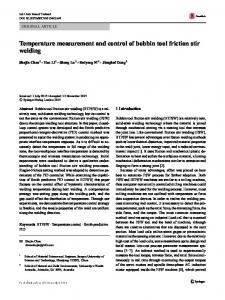
Figure 1: Tool and directional conventions.
settings for a given situation. To some extent this is true for the CFSW, but even then not entirely. It is certainly untrue for the BFSW and the issues are particularly acute for thin sheet, less than about 6 mm, whereas thick plate of say 25 mm is not problematic to the same extent. There is a small but growing research literature on this type of tool and its application to thin sheet, which seeks to overcome these problems [7, 8]. The present paper reports on empirical results from friction stir welding trials, for the BFSW configuration, with the focus on the dynamic interaction between the tool and the substrate, and hence also the control characteristics. This work was initiated because the authors noted in their empirical testing that the addition of a load-cell platform under the substrate significantly affected the kinematics of the tool and reduced the quality of the weld, compared to the same setup without the load-cell platform. This drew attention to a coupled problem whereby the stiffness of the setup affects the tool-substrate interaction, via forces and displacements, and this affects the weld quality. The paper explores this causality.
2. Background 2.1. Welding Forces. During the welding process, mechanical force is generated at the interface between the tool and workpiece. This is measured in the 𝑥, 𝑦, and 𝑧 directions relative to the weld direction; see Figure 1. A number of studies have quantified these forces as a function of the process parameters. The spindle speed influences the mechanical forces, with slow rotation causing higher mechanical forces [9], especially in the 𝑦 and 𝑧 directions [10]. The 𝑧 force appears to be most affected by tool shoulder diameter, rotation, and welding speed and the 𝑦 force by welding speed, pin diameter, and interaction between tool diameter and rotation speed [11]. Other works involving force measurement have included the effect of varying speed and rotation [12] and a comparison between CFSW and BFSW [6]. The literature generally expects that the magnitudes of these forces will correspond, in ways incompletely defined, to the welding process parameters. However the actual
mechanics of the tool are complex, and the kinematics do not show a simple constant-velocity progression in the 𝑦-axis as the case might first seem. The slenderness of the BFSW tool means that it moves in a dynamic way relative to the substrate, and various complex oscillations in the kinetics and kinematics may be observed. These dynamics arise from the interaction between the tool, the substrate, and the plastic material flow that is stirred around the tool [13]. The resulting dynamic forces are propagated into the welding machine; this is usually a computer numerical control (CNC) machine of the milling-type configuration. Consequently, there can be an interaction between the dynamics of the welding process and the control system of the CNC machine. Only a few studies have considered how the dynamic response of the tool might affect weld quality. For example, a bilobed polar plot has been used to visualise the dynamic response [14]. That study was focused mainly on tool features. The forces were captured by a specialised instrumented tool head. Those authors reasoned that the highest strength weld corresponded to low angular rotation values of the maximum force and high ratios of maximum-to-minimum force on the tool. Polar plots have also been used [15] to represent resultant force. In that study, tool features were constant, but the spindle speed and travel speed were varied. They concluded that defect-free welds should be expected when the resultant force acts in the region between the trailing edge and advancing side. Others have adopted signal processing methods, namely, fast Fourier transform (FFT), to reveal frequencies of the force signal [16]. This method has been used to characterise the trends for different tool run-out [17]. Imbalanced 𝑥 and 𝑦 force magnitudes have been associated with greater tendency to produce voids in the weld [13], though the mechanisms are incompletely understood. These imbalanced forces only occurred at low frequency; hence the study concluded that prevention thereof could reduce voids. The same team applied neural networks to the Fourier trends to predict good and bad welds and correctly identified 95% of the testing set [18]. The main trends identified were that bad welds had forces of high magnitude but low frequency. However this of itself does not explain the underlying causality. It could even be that some other factor caused the bad welds which then caused the observed force characteristic. Issues with fixtures being associated with bad welds were identified by Arbegast and Patnaik [19], in the aluminium context. However, the growth of the knowledge in the specific area is slow. Consequently there is a need to better understand the causal relationships between process parameters and weld quality. Several subparts to this problem may be identified. 2.2. Gaps in the Body of Knowledge. There are kinetic and kinematic aspects of this problem, which are related via the stiffness of the substrate material and the stiffness of the tool [20]. Besides that, there are also effects due to the finite mechanical stiffness of the apparatus (e.g., CNC machine) and the effective stiffness of its electronic control strategy. These issues can be classified as a dynamic interaction between the tool and the substrate. At this stage the problem is poorly understood.
International Journal of Manufacturing Engineering The first gap is the imperfection of existing measurement methods. Although there have been efforts to study these dynamic signals, there are still many areas that need to be covered. For example, previous works are only focused on the dynamic response through force measurement or through the proxy of complex mathematical calculations. Furthermore, previous studies were primarily for a single-sided shoulder tool, rather than the bobbin tool, which is expected to have very different characteristics. There is no known research into characterising the BFSW process variability based on the dynamic response. Although the underlying physics for the CFSW is applicable to BFSW, it is apparent that the additional shoulder affects the functional behaviour of the tool [21]. The second gap is the limited number of variables admitted to most analyses and experiments. Existing research into the BFSW has focused on the influence of only a few variables: primarily linear and rotation speed, material type, and a variety of tool features. Even so the landscape of all possible process settings has not been explored typically because each of the above variables has been tested with only a few levels in anyone study [22–24]. Other production variables can be anticipated that have not received any attention. Specifically, the causal effect of machine-type and tool holder has not been addressed. This is an important potential limitation because reported studies use specific hardware which varies greatly in its construction, including dedicated friction stir welding machines [5], milling machines [25], or robotics [26]. These machines have differences in rigidity, clamping, induction motor characteristics, and controller algorithms. However these characteristics are invariably taken for granted: they have not been considered variables in their own right and are seldom reported on in the literature. The authors’ experience shows that even the addition of a stiff load-cell platform under the substrate can significantly affect the kinematics of the tool and the quality of the weld, and this is attributed to the small additional compliance that it inserts in the load path. It is also to be expected that the tool-substrate interaction will be affected by the mechanical stiffness of the whole apparatus and the effective stiffness of its control strategy. There is risk that these machine-specific characteristics could be having a profound covert and underreported effect on the welding process. This would be consistent with the observation that the external validity of many BFSW studies is poor; that is, the process settings are difficult to transfer from one situation to another. No studies have explored these covert stiffness variables. Similarly the vertical fixation of the fixed-gap bobbin tool also has a stiffness, especially if it floats, and this has not yet been reported. There is research on bobbin tools that are controlled by an actuator for positioning and rotation, known as adaptive bobbin tools [27]; see also [5, 28]. The success of this type of tool has been shown for different grades of aluminium, thickness, and conditions [29, 30]. However, the adaptive tool head involves specialised hardware that is costly. A simple approach is preferred so that the technology can be widely applied in industry. Although a simple version of floating tool has been presented by The Welding Institute for thick material using a dedicated FSW machine, there is no literature on the feasibility of using a conventional floating
3 tool holder on a CNC machine, especially not for a different welding regime like the BFSW of a thin plate aluminium. Thus, there is a need to understand the dynamic engagement of the BFSW tool with the welding substrate. This dynamic engagement is evident in the time-varying forces and torques in the different axes, which in turn are consequences of processes, imperfectly understood, involving the way the tool grabs and releases plasticised weld material, the stiffness of the mechanical systems that hold the tool and the substrate, and the way the CNC control system interacts with the dynamic response. This is worth exploring for the potential to improve weld quality and reproducibility in thin plate BFSW.
3. Experimental Approach 3.1. Purpose. The purpose of this work was to assess the dynamic response of the BFSW processes for two primary variables: different CNC machines and controllers (two levels) and tool fixation (two levels). The following secondary variables were admitted to the study: tool features, interference fit of tool to substrate, travel speed, and spindle speed. The research was explorative and hence selected key combinations of the above variables, as opposed to attempting a full factorial design. The material under examination was thin plate aluminium, specifically Al6082-T6. This is a difficult material to weld, particularly in the thin state, and is prone to forming defects. It has a narrow window of process settings, but there is disagreement in the literature about these ranges [31, 32]. Consequently, from a production quality perspective, the process for welding this alloy is not in control, and this strongly implies that other covert variables are involved. A factorial design of experiments approach is only useful if all the key variables have been identified, and since this is not the case for this alloy it is prudent to take a more exploratory approach. 3.2. Approach. Material of extruded plate AA6082-T6 with dimensions of 270 mm × 260 mm × 4 mm was friction stir welded in a butt joint configuration using a bobbin tool. The variables under examination were (1) tool features, (2) interference between tool and substrate, (3) type of machine, (4) tool holder, and (5) welding parameters. Tool Features. Two fixed-gap tools were fabricated from H13 material. The pin feature variables admitted to the study were cylinder pin and cylinder pin with three flats. The shoulder diameter and the pin diameter were 12 mm and 6 mm, respectively. These tools had flat shoulders. These features are representative of typical bobbin tools for thin plate [21, 32]. Other features that can be included on such tools are threads or other geometric protrusions on the pin and scrolls on the shoulder. Such features are common on tool for thick plate, as the geometry is easier to manufacture, and common opinion holds that they are necessary in the thick situation. However these features have marginal or uncertain efficacy in the case of thin material, and coupled with the difficulty of manufacture with small tools, this means that such features are used only occasionally. The fabricated tools for this study are shown in Figure 2.
4
International Journal of Manufacturing Engineering
𝜙13 𝜙12
𝜙6
(i) 𝜙13
5.6
0
3 flats
A
A
(ii) (a)
(b)
Figure 2: Bobbin tool. (a) Fabricated tool. (b) Cross section at pin area, A-A. (i) Cylinder pin. (ii) Cylinder pin with 3 flats. Figure is not to scale and the unit of the drawings is in mm.
Interference between Tool and Substrate (“Shoulder Gap”). Two settings were applied, namely, 0% and 3.75% interference. Tools were produced at 3.85 mm and 4 mm of shoulder gap (distance between top and bottom shoulder). Interference refers to the degree to which the tool-gap is smaller than the thickness of the substrate plate. This is an important variable for weld quality [20]. The mechanism is believed to be that the compression packs the weld zone with material; or to put it in another way, the compression replaces the material that is inevitably lost from the weld due to ejection at tool entry, swarf, and chips.
Floating tool holder
Bobbin tool
Fixture
Figure 3: Floating tool holder.
Machine Type. Two different brands of CNC machine were tested. These were comparable in physical size, both were 3axis CNC machines, but from different manufacturers. The machines were (a) 1996 Okuma MX-45VAE with OSP 700 M control unit and (b) 2000 Richmond VMC 600 with Fanuc control unit. The Okuma machine had a 10-horsepower spindle motor and the Richmond had 14-horsepower capability.
The tool was then positioned between the plate thicknesses prior to welding. When the tool rotated and travelled, the tapered substrate aided self-positioning of the tool. The use of a commercially available floating tool holder in the CNC machine market for FSW is believed to be a novel approach because there is no mention of such an idea in the literature.
Tool Holder. The tool could be fixed in the spindle or allowed to float vertically (in the axis of the spindle) with the application of the floating tool holder. A floating collet as used for tapping threads was used in the latter case; see Figure 3. This is a commonly available tool holder, though not previously applied to BFSW. It was expected that a floating tool would permit the tool to follow variations in plate thickness or thermal distortion in the vertical axis, both of which do occur in practice [33]. The floating tool holder had a vertical tolerance of 4 mm and a downforce of about 14.5 N as well as fitting clearance of about 1 mm. It consisted of adapters for various sizes of tools. To take the advantage of the floating tool holder, substrate plates were tapered at the entry position.
Welding Parameters. For the welding parameters, the tests were done in the range of 800 rpm–1000 rpm of the spindle speed with 50 mm/min to 200 mm/min of the travel speed. These parameters were selected by the authors from the prior experiments. The current literature lacks consistency in the parameters suggested for similar thickness of aluminium alloys. Some studies have used slower spindle speed [30, 32] and others used higher [34]. However, in the present study, there was a fixed entry parameter of 800 rpm spindle speed and 45 mm/min travel speed, causing an entry region of about 30 mm. However, data collected in the entry phase were not used for the present analysis. The reason was to eliminate the inconsistent signals related to material readiness (entry) and availability (exit) as well as heat level.
International Journal of Manufacturing Engineering
5
Clamp meter
NI DAQ
(a)
(b)
Figure 4: Measurement of current using the current (𝐼) clamp meter on a spindle input. (a) Clamp meter. (b) Workstation.
3.3. Instrumentation Methodology. Process responses generated during the welding process were measured using a current (𝐼) clamp meter which was attached at the input current of the spindle motor; refer to Figure 4. The hardware comprised a National Instrument (NI) data acquisition (DAQ) platform. LabVIEW software was used and a fast Fourier transform (FFT) approach was adopted to study the signal trends. This was done in the MATLAB 2013b environment. The dynamic measurement and analysis of motor current are uncommon in the FSW literature and a potential area to explore. This approach is inexpensive and quick to set up and therefore has the potential for real-time control. In addition it avoids the limitations of other instrumental approaches, where it is not uncommon for transducers to be displaced during the welding process or subject to high temperature.
4. Results The FFT represents the frequency of occurrence of various magnitudes of the measured variable (electrical current) produced as a response to the BFSW process. Three frequencies can be identified: fundamental, harmonic, and subharmonic. The magnitudes of these frequencies were found to depend strongly on the process parameters used in each case. The fundamental frequency (𝑓) was the main frequency associated with the system and corresponds to the rotation speed of the spindle. The harmonic frequencies were the major multiples of the fundamental frequency (𝑥⋅𝑓, where 𝑥 is an integer) and the subharmonic frequencies were the frequencies below the fundamental frequency (𝑦 ⋅ 𝑓, where 𝑦 is the fractional number). Other low amplitude signals also blended into these frequencies, and these were intrinsic to the rotating motor. 4.1. Machine Sensitivity. Figure 5 depicts the responses of the current clamp meter measurement from the 3-axis CNC machines. Based on the amplitude plots, it can be seen that the Richmond machine has an electrical control system with less sensitivity towards changes of the process loading, besides having a slight peak of low frequency at high travel speed. The fundamental frequency of the Richmond machine was comparable in both feed settings.
On the other hand, the Okuma machine showed lower frequency signals for both settings. This included the presence of subharmonic frequencies at 1/3, 1/2, and 2/3 of the fundamental signal. This implies that the system has low impedance. This can be the result of motor efficiency or the electrical components [35]. In general, with constant voltage supplied to the system and with a low impedance condition, the current input will rise. Low frequencies, especially subharmonic frequencies, are known to affect the stability of electronic components; hence they can affect the machine stability. Based on Jaber et al. [36] it is known that when subharmonic frequencies are present, the stability of the motor may be jeopardised by decreasing torque and motor speed. This is also consistent with other results [13, 18] where bad welds were associated with high current amplitudes at low frequencies. The welds produced by both machines had internal defects, where the cross section was not entirely solid with weld material. This is characterised by a longitudinal tunnel defect. This was not entirely unexpected given the known difficulty of welding thin plate 8082-T6. These defects are consistent with other observations that this type of observed current fluctuation often indicates poor welds [37]. The present results show that in marginal welding situations the machine factor has less to do with the physical size of the machines or the power of their drives, but the nature of the electronic control systems, particularly how the electrical control system responds to dynamic changes of the load during welding. We propose that this changes the position of the tool relative to the weld-pool and thus alters material flows within the weld, which causes variability in weld formation. This is discussed later. 4.2. Tool Holder: Fixed versus Floating. The self-reacting tool has been suggested by TWI in the early stages of the technology invention. However, the adoption and publication of results are limited, and the implementation of dynamic float control is complex and expensive [38]. In the present work a novel floating tool holder was used for adaptable tool positioning and for continuous contact with the substrate. The Okuma machine was selected for further investigation as its electrical components had been shown to be more sensitive.
6
International Journal of Manufacturing Engineering 0% interference, 6 mm diameter cylinder pin
800
600
500
500
400
f
300 200
400
f
300 200
100 0
Float, 800 rpm, 400 mm\min, Richmond
700
Float, 800 rpm, 200 mm\min, Richmond
600 Amplitude
Amplitude
700
0% interference, 6 mm diameter cylinder pin
800
100
2·f
0
4
8
12
16
20
24
28
32
36
40
44
0
48
2·f
0
4
8
12
16
Frequency (Hz) (a)
1/2 · f
500 300
2·f
200
Float, 800 rpm, 400 mm\min, Okuma
400 f
300 2/3 · f
2·f
100 4
8
48
500
200
100 0
44
600
f
400
0
1/3 · f
700 Amplitude
Amplitude
600
40
0% interference, 6 mm diameter cylinder pin
800
Float, 800 rpm, 200 mm\min, Okuma
700
36
(b)
0% interference, 6 mm diameter cylinder pin
800
20 24 28 32 Frequency (Hz)
0
12 16 20 24 28 32 36 40 44 48
0
4
8
12
16
Frequency (Hz)
20
24
28
32
36
40
44
48
Frequency (Hz)
(c)
(d)
Figure 5: Machine variability current (𝐼) response; in all cases it runs on rigidly supported substrate. 3.75% interference, 6 mm diameter cylinder pin with 3 flats
800
600
500
f
400 300
2·f
200
Amplitude
Amplitude
600
500 400
f
300 200
2·f
100
100 0
Fixed, 800 rpm, 200 mm\min, Okuma
700
Float, 800 rpm, 200 mm\min, Okuma
700
3.75% interference, 6 mm diameter cylinder pin with 3 flats
800
0
4
8
12 16 20 24 28 32 36 40 44 48 Frequency (Hz) (a)
0
0
4
8
12
16
20
24
28
32
36
40
44
48
Frequency (Hz) (b)
Figure 6: The response of float and fixed tool holder of the Okuma machine with rigid tool support.
Results of the tests, based on the FFT of the current response, showed no obvious difference between floating and fixed tool; refer to Figure 6. Both had noticeable low frequency components and high magnitude at the harmonic frequencies. However, the low frequency magnitudes were slightly higher for the fixed tool. This difference can also be seen in the current consumed by the motor. The fixed tool used a mean current of 8.32 ± 0.44 A while the floating tool consumed about 7.98 ± 0.37 A. The higher current consumed on the fixed tool holder indicates that the controller was experiencing higher resistance from the tool. Two causes are anticipated. The first is
that the fixed tool could not follow the natural variations in the top and bottom plate surfaces; these variations arise due to the thermomechanical stresses during the welding process [39], even if the plate itself is initially flat as in this case. The second is that the fixed tool has less mechanical compliance in its interaction with the substrate. Tool deflection is constrained, and consequently the tool is forced to have constant contact with harder material on the advancing side as it travels forward. This is consistent with the observation of tools taking an “off-cantered” orientation [40, 41]. This is proposed as the mechanism that increases the forces and the demand for electrical power.
International Journal of Manufacturing Engineering
7
3.75% interference, 6 mm diameter cylinder pin with 3 flats 2800
f
Fixed, 800 rpm, 50 mm\min, Okuma
2000 1/3 · f
1200 800 400 0
0
4
8
12
4/3 · f
16
24
1200 400
5/3 · f
20
2000 1600 800
2·f
2/3 · f
Float, 800 rpm, 50 mm\min, Okuma
2400 Amplitude
Amplitude
2400 1600
3.75% interference, 6 mm diameter cylinder pin with 3 flats 2800
28
32
36
40
44
48
0
f
0
4
8
Frequency (Hz) (a)
12
2·f
16
20 24 28 32 36 40 44 48 Frequency (Hz) (b)
Figure 7: Welding at 50 mm/min. (a) Fixed tool holder. (b) Floating tool holder. All tests were performed on rigidly supported substrate.
On the other hand, the difference in current between the fixed and floating was not large, and this is attributed to the spindle motor being under less demand, having ample spare torque capacity to cope with the load changes. Another work conducted by the authors indicates that the 𝑦-axis (the direction of the travel motor) is more sensitive to the load changes. The 𝑧-axis force can be minimum or near to zero for a self-reacting tool [30]. This is attributed to the high forces needed to move the tool through the material and the amount of material to be stirred. Better weld quality should be expected at faster feed rate, due to consistent fresh material being supplied into the stirring zone. An interesting finding was observed when the tool was travelling at low feed of 50 mm/min. The FFT response is shown in Figure 7. At low feed a high friction temperature should be expected [11, 42]. It is natural, but it is wrong to assume that higher heat facilitates better welding. Intuitively one would expect that higher heat would reduce the force on the tool [43] and provide more time to dissipate internal stresses [44] and hence result in a smoother locus for the tool. However, this is observed not to be the case. It can be clearly seen that the fixed tool produced significantly more subharmonic frequencies and also greater amplitude of the fundamental frequency, compared to the floating tool. During the fixed tool run, the CNC table was visibly observed to be driven in a jerking motion, and the welded plate was subjected to noticeable 𝑦-axis (longitudinal) deflections. In addition, the operating noise and vibration were noticeably greater, though these were not quantified. However, these effects were absent when the floating tool was used. Based on mean current measurement, the fixed tool has a high mean current of 6.54 ± 0.86 A and the floating tool consumes a much lower current of 1.59 ± 0.21 A.
5. Discussion 5.1. Interpretation of Results 5.1.1. CNC Control Strategies Affect Weld Quality. The unexpected findings with floating-fixed tool holders can be explained through current consumption. This is because current supplied to the motor is dependent on the demand. This
CNC table
Rigid support
Material
Tool
Tool holder
Spindle motor
Figure 8: The connection of the welding components.
demand is determined by speed and load. The closed-loop control of the CNC machine attempts to deliver a constant speed. In the case of FSW at low feed rate, only a small amount of current was required for the table motion, but the welding process led to sudden increases and changeable current demand. It would appear to be the rapid changeability of load that the controller struggled to cope with, not the magnitude of the force per se. The problem is that the tool sticks or falters in its longitudinal locus (𝑦-axis), as it suddenly engages colder and harder material or jerks to the side (𝑥-axis). To compensate, the CNC control has to quickly adjust the current to overcome the friction and maintain the commanded feed rate. The controller increases the current to break the barrier and get the table moving. Then the tool unsticks; hence the tool-forces reduce, requiring a sudden reduction in the current to maintain the feed rate. Hence the jerking motion is evident in the 𝑦-axis deflection of the tool [41, 45]. This also means that the tool is biting off fresh material in a jerking rather than a steady manner, which has the effect of interrupting the supply of material into the weld region. In turn this disturbs the steady laying down of weld material in the wake of the tool and hence reduces weld quality. In FSW there is a significant mechanical load-bearing path between the CNC table, via the welded substrate and tool, to the spindle motor. In conventional milling process the exit of swarf and chip fragments releases stress, but that escape is unavailable in FSW and indeed is disadvantageous as conservation of mass means that loss of material causes weld tunnel defects. Therefore, any abrupt motion changes at the level of the table in FSW will affect the spindle motor too; refer to Figure 8. Thus, although the FFT plot was not measured at the table drive unit, the impact of low feed at high process load can be characterised from the spindle motor current. This is consistent with Brendel and Schneider [16] who noted that process adjustment could be seen in spindle motor trends.
8
International Journal of Manufacturing Engineering
Clearance allowance Tool
Tool holder
(a)
(b)
Figure 9: Illustration of the cross section view. (a) Fixed tool holder. (b) Floating tool holder. The image is exaggerated for effect.
(a)
(b)
Figure 10: Weld width. (a) Fixed tool holder. (b) Floating tool holder. Both welded using Okuma machine spindle speed of 800 rpm and travel feed of 50 mm/min.
5.1.2. Unwelcome Mechanical Compliance in Tools. The reason the floating tool had a much lower effect on the amplification of the feeding current is attributed to the fitting clearance. The fitting clearance provides allowances to the tool motion so that the tool was not directly forced to continuously stir an amount of hard material; see Figure 9. The clearance gave some degree of freedom (DOF) to the tool, hence reducing the stress generated at the tool interface, and imposed less load on the electrical components. However the DOF also introduced higher tool deflection out-of-alignment, which puts the tool shoulders (which are a light interference fit with the substrate) into an angular misalignment with the substrate. This induced secondary stresses and altered the material flow in other ways. The proposed transportation mechanism will be explained later.
Figure 10 represents the effect of tool motion altering the material transportation. It can be clearly seen from the weld width that the floating tool holder produced wider weld width than the fixed tool holder. The evidence of deep lurches was also present on the surface of the weld, which is related to the deflection of the tool in the 𝑥- and 𝑦-axes. On one hand, the DOF is a good feature to prevent high load on the machine, but it also interferes with the production of a good weld. Presentable welds were only recorded at low feed rate, but at high feed rate a continuous tunnel defect was observed, and a more extensive rind of flash was produced. Therefore, it is believed that a tighter tolerance of floating tool is required as used in [28, 30]. The reason relates to the tool positioning as illustrated in Figure 11.
International Journal of Manufacturing Engineering
Fk
9
Spring Tool holder
Tool Fa
Material
(a)
(b)
Figure 11: Side view of the floating tool holder. (a) Self-position; 𝐹𝑎 > 𝐹𝑘 . (b) Tilted.
The process details are anticipated as follows, for the unsuccessful welds using a floating tool: (i) Travel force (𝐹𝑎 ) in the 𝑦-axis is invariably higher than the spring force associated with the tool floating force (𝐹𝑘 ) in the 𝑧-axis; 𝐹𝑎 > 𝐹𝑘 . Although the tool was positioned between the floating tolerances, the spring force, 𝐹𝑘 , pushes the tool downward. As the tool starts to enter the substrate, the tool is unable to slide upward for repositioning, due to the high 𝑦-axis forces causing frictional lock-up of the 𝑧-axis freedom of the floating tool holder. As a result, the tool shoulders end up being misaligned to the surfaces of the weld substrate. This causes the material to be torn off, creating the observed excessive flash at the top surface of the substrate. A similar effect can be seen in CFSW when high plunge force is introduced [46]. Material volume is displaced to accommodate the tool entry. (ii) When the tool travels at high speed, the tool tilts backward as reaction to the forward feed force (𝐹𝑎 ). The tilted angle is amplified by the presence of the clearance allowance in the case of the floating tool holder. There is also an intrinsic deflection of the tool itself, especially for thin pins. As a result, the edge of the tool shoulder digs into the material: on the upper surface the leading edge digs in and on the lower surface the trailing edge. This increases the amount of flash ejected. However, this is not the case for low feed rate. With longer contact time at a location, the tool is able to move the weld substrate material out the way; hence less tool deflection arises. It is suggested
that the effects are dependent on the severity of the misalignment. Also, any material ejected from the weld zone is an opportunity for a void to form further down the locus, due to mass conservation effects [47]. 5.1.3. Interaction of Tool Features and Machine Control. The work shows that the electrical characteristics of the spindle motor and its controller affect the weld outcomes. The demand spectrum is related to the process load, which in turn also depends on the setup parameters. Different CNC machines were shown to have very different electrical characteristics, and these affect the repeatability of the welding process. It is not surprising that a wide range of welding parameters are suggested in the literature, given that machine characteristics have generally not been taken into account. For example, for a similar material at a similar thickness, Colligan et al. [34] produced sound welds at higher feed rates than other researchers. Additionally, Liu et al. [32] managed to produce sound welds at different process settings using a featureless tool; this is challenging to achieve and has not been replicated. Both of these cases suggest that other variables, such as the machine-specific parameters identified here, were acting as covert variables. Thus, the authors identify that the machine electrical characteristics are important production variables for friction stir welding. An interesting trend was found at 0% interference fit of a featureless tool and at 3.75% interference fit of a tool with three flat features on the pin. It appears that the presence of the subharmonic frequency is related to the tool motion affected by the interaction of tool features and machine control. The effect of subharmonic frequency in the CNC machine will be explained later.
10
International Journal of Manufacturing Engineering
5.1.4. Frequency Resonance. Rotating machines are prone to have frequency resonance at harmonic and subharmonic frequencies [35, 48]. The CNC machines differ in their ability to accommodate or damp this signal in the circuit. In situations where the weld process is operating within a wide process-window of stability, the electrical capabilities of the system may not be important. However, for difficult-to-weld situations like that are encountered here, the electromechanical interaction causes amplified and excited subharmonics, with negative consequences for weld quality. This recovers the observation of others [49] who associated subharmonic frequencies with noise and vibration. The Richmond machine was able to handle the instability produced at the welding interface. However, this was not the case for the Okuma machine. Besides that, noise and vibration were also present, especially at low feed rate. In this condition, the material flow was altered due to machineinduced jerking motion, thus adversely affecting the quality of the weld. Based on the findings, it is proposed that the “stick-slip” motion is subject to two conditions: (1) tool engagement and (2) machine characteristics, particularly the stiffness in the entire load path including the virtual stiffness created by the motor controller. In this case the effect was clearly observed under low feed rate; however, this is generally only relevant to the entry stage of the BFSW process. Nevertheless, slip-stick is known to be involved in material transportation in FSW, as has been shown by mathematical modelling [50]. However the highly variable type of slip-stick motion observed here is likely to interfere with those transport mechanisms; that is, the machine control indirectly affects the material transport within the weld. Other tests conducted by the authors, not presented here, indicate that better BFSW weld quality is associated with lower FFT spectrums. 5.2. Proposed Mechanics. The findings lead us to propose a specific mechanics for inside the weld region. There are two parts to this: how the tool engages with and moves the substrate material and an overall proposition of causality for weld quality. 5.2.1. Proposed Mechanics for the Material Transportation. Based on these findings, we propose the following mechanics for the material transportation within the weld: (i) The flat features create a dynamic swept volume of material; hence material is transported in discrete lots. To stir a volume of material, high energy is required, which is contrary to the usual CNC control strategy of low current applied for low feed rate. As explained earlier, the CNC closed-loop monitoring mechanism increases the current to overcome the resistance. However, the system will then need to reduce it quickly to meet the set feed rate. This causes jerking motion which further influences the longitudinal deflection of the tool. Additionally, this behaviour was only seen for the fixed tool holder. As discussed before, the floating tool introduced additional degrees of freedom for the tool to release the strain developed in the system but created other problems.
(ii) The interference between the tool and substrate causes grabbing of the material by the shoulders and hence heat generation. The importance of shoulder gap in bobbin tools has previously been identified. With less interference, so less material is seized; hence the tool deflects less. (iii) A greater interference between shoulders and substrate causes higher frictional forces at the leading face than trailing face. The tool rotation then forces the tool laterally towards the advancing side. Referring to the 0% interference and featureless tool, the process has poor material transportation and heat generation. The controller had to adjust the current appropriately in order to drive the tool through the material. 5.2.2. Causality Model. The results of this study and the proposed relationships of causality between the variables are graphically summarised in Figure 12. This model complements and extends other works [21] by including the effect of different machines and type of tool holders. The model represents the proposed casual relationships, as expressed above, as expressed in integration definition zero (IDEF0) notation. This summary is offered as a guideline to explain weld repeatability issues as well as optimise weld process. It may also be helpful in consolidating the research body of knowledge and directing future research efforts. 5.3. Outcomes. This investigation makes the following original contributions: (i) Machine. It has been shown that machine-type is a variable that needs to be given attention in the selection of FSM process parameters. Different manufacturers use different approaches to electrical control, and these affect the quality of the weld. As shown above, when welding was done at a low feed rate, jerking motion tends to be produced. This motion alters the slip-stick interaction between tool and substrate and interferes with the welding process. A rigid system will transfer the instability of the working interface to the machine; hence there is more demand on the control system to make frequent adjustments, as evident in results of current monitoring of the spindle motor. (ii) Tool Holder. The friction tool should be firmly held by the system to minimise deflection. Although deflection might seem a useful mechanism for releasing the process stresses, it has negative consequences as it introduces tool positioning problems. Besides that, the clearance allowance that is associated with the CNC floating tool holder influences the material transportation within the weld. At low feed, the tool can use this as an advantage, but at high speed the problem with tool positioning overcomes this advantage, resulting in unacceptable welds. (iii) Qualitative mechanics has been proposed for the mechanism of material transportation within the weld zone. This is novel in that it accommodates
International Journal of Manufacturing Engineering
11
Longitudinal deflection
Lateral deflection
Process setting: spindle speed; feed rate
Floating tool holder: tilted (clearance)
Mechanical engagement of tool with substrate
Signal response FFT trends: Floating tool: produced low frequency at higher magnitude
Flat feature: swept volume
Minimum interference: low frequency Heat generation Subharmonic: jerking motion and deflection
Tool features Material stirring (mixing)
Weldment
Shoulder gap (interference) CNC tool holder
Cylindrical pin with 3 flats
Stick-slip Low feed rate: jerking motion (longitudinal deflection)
Rigidity/ stiffness Fixed Machine
Floating
Lateral deflection: Controller/ machine components
% of interference
Potential defects: voids, closed/open tunnel, closed/ open void, and flash (wave/ continuous), Size of the weld width
Floating tool: clearance
Low feed (conventional CNC machine)
Lurches
Figure 12: A causal model for bobbin friction stir welding on selected factors.
the dynamic (nonsmooth) interaction of the tool with the substrate and describes how this is affected by other stiffness variables. 5.4. Limitations. This has been an exploratory study and the validity of the conclusions is limited by the small sample size (no statistical comparisons were possible), the limited range of variables admitted to the study (other covert variables might exist that have yet to be discovered), the incomplete experimental design (not all variables were tested against each other), and the lack of prior optimisation of process parameters (tool features, spindle speed, and travel speed). This is a complex area of study and these limitations apply in some form to most of the published works. In the present case the main limitation is the small sample size. It should be noted that the tests were limited to one grade of aluminium with specific sizes. Material grade is known to be an important variable in FSW, and this somewhat limits the external construct validity of the explanations developed here, that is, the ability to apply the findings to other materials. More positively, the types of weld defects encountered are consistent with other materials, and the material transportation mechanisms proposed here is not materialspecific. So if the defects can be eliminated or minimised in
this material then it is a reasonable to expect improvements in other materials. Indeed one of the reasons for conducting the present tests with AL6082-T6 was due to the fact that it is such a difficult and unpredictable material to weld. It is an especially difficult material in the thin state. The present work has deliberately focused on thin material, but only one thickness was used. The findings therefore do not address the important question of why thin material behaves so differently or where the transition lies between thick and thin. 5.5. Future Research. Opportunities for further research are plentiful. This includes further experimental works, effects of tool features, and process rigidity and its relation for obtaining acceptable production setting.
6. Conclusions The overall work has demonstrated the effects of the selected process variables through the dynamic process response of BFSW. The implications of the works are as follows: (a) Shoulder gap is an important feature to ensure toolsubstrate contact. Loose fit between shoulder and substrate can cause lateral deflection of the tool and adverse quality outcomes.
12
International Journal of Manufacturing Engineering (b) The machine is one of the sources of variability. For the conventional CNC milling machine low feed rate tends to cause jerking motion (longitudinal deflection on tool) that adversely affects the material flow within the weld. (c) The CNC floating tool holder has high clearance, which can cause tilted position and misalignment and hence poorer welds, and is not recommended for BFSW. (d) Process response can be easily, fast, and inexpensively quantified using a current clamp meter. The FFT method can then be applied to reveal the trends. This has the potential to provide future real-time noninvasive measure of weld quality. (e) Low frequency and subharmonic frequencies are an indication of unstable welding processes.
Additional Points (i) Data are presented for dynamic response signals for the double-sided tool (bobbin). (ii) Tool deflection is related to the presence of subharmonic frequencies. (iii) Floating tool holder tolerance is the source of tool deflection. (iv) Frequency analysis has the potential to be developed into a real-time, noninvasive, and inexpensive method for detecting weld quality.
Competing Interests The authors declare no conflict of interests regarding the publication of this paper. The research was conducted without commercial or financial benefit from a third party, other than the provision of raw aluminium material from a commercial boat builder and scholarship funding for Mohammad K. Sued from the Ministry of Higher Education, Malaysia. There was no third-party influence in the work: its approach, interpretation of data, writing, or submission decisions.
Authors’ Contributions Mohammad K. Sued conducted the tests, performed the signal processing, and proposed the conceptual model. Both authors developed the explanations and wrote the paper.
Acknowledgments The authors acknowledge the provision of raw materials by INCAT (Tasmania, Australia) and Mr Steve Tomsett of the Christchurch Institute of Technology (CPIT, Christchurch, New Zealand) for their permission for using their facility. They also thank Messrs Scott Amies, David Read, and Julian Phillips, all from the University of Canterbury, for technical support. The main author would like to thank the Ministry of Higher Education Malaysia and Universiti Teknikal Malaysia Melaka for the scholarship that made the studies possible.
References [1] R. S. Mishra and Z. Y. Ma, “Friction stir welding and processing,” Materials Science and Engineering R: Reports, vol. 50, no. 1-2, pp. 1–78, 2005. [2] W. M. Thomas, E. D. Nicholas, M. G. Needham, and D. J. Templesmith, Friction Stir Butt Welding.International Patent Application PCT/GB92/02203, GB Patent Application 9125978.8, US Patent 5.460.317, 1991. [3] J. Carstensen and J. F. Dos Santos, “Application of FSW and FSSW on advanced automotive structural applications,” in Proceedings of the 9th International Friction Stir Welding Symposium, Huntsville, Ala, USA, 2012. [4] I. Bordesoules, A. Bigot, C. Hantrais, T. Odievre, and J. Laye, “Aircracts structural parts demonstrators manufactured using friction stir welding,” in Proceedings of the 9th International Symposium on Friction Stir Welding, Huntsville, Ala, USA, 2012. [5] F. Marie, D. Allehaux, and B. Esmiller, “Development of the bobbin tool technique on various aluminium alloys,” in Proceedings of the 5th International Symposium on Friction Stir Welding, Metz, France, September 2004. [6] P. L. Threadgill, M. M. Z. Ahmed, J. P. Martin, J. G. Perrett, and B. P. Wynne, “The use of bobbin tools for friction stir welding of aluminium alloys,” Materials Science Forum, vol. 638–642, pp. 1179–1184, 2009, Proceedings of the Thermec 2009, Parts 1–4. [7] F. Marie, B. Guerin, D. Deloison, D. Aliaga, and C. Desrayaud, “Investigation on bobbin tool friction stir welding of 2000 serie aluminium thin sheets,” in Proceedings of the 7th International Friction Stir Welding Symposium, Awaji Island, Japan, 2000. [8] K. J. Colligan, “Low-cost friction stir welding of aluminium for littoral combat ship applications,” in Proceedings of the 8th International Friction Stir Welding Symposium, Timmendorfer Strand, Germany, 2010. [9] C. Chen and R. Kovacevic, “Thermomechanical modelling and force analysis of friction stir welding by the finite element method,” Proceedings of the Institution of Mechanical Engineers, Part C, vol. 218, no. 5, pp. 509–520, 2004. [10] M. Assidi, L. Fourment, S. Guerdoux, and T. Nelson, “Friction model for friction stir welding process simulation: calibrations from welding experiments,” International Journal of Machine Tools and Manufacture, vol. 50, no. 2, pp. 143–155, 2010. [11] R. Kumar, K. Singh, and S. Pandey, “Process forces and heat input as function of process parameters in AA5083 friction stir welds,” Transactions of Nonferrous Metals Society of China, vol. 22, no. 2, pp. 288–298, 2012. [12] H. Su, C. S. Wu, A. Pittner, and M. Rethmeier, “Simultaneous measurement of tool torque, traverse force and axial force in friction stir welding,” Journal of Manufacturing Processes, vol. 15, no. 4, pp. 495–500, 2013. [13] W. J. Arbegast, “Dynamic response of friction stir welding forces and relationship to weld quality,” in Ptoceedings of the 7th International Conference on Trends in Welding Research, Pine Mountain, Ga, USA, 2005. [14] D. G. Hattingh, C. Blignault, T. I. van Niekerk, and M. N. James, “Characterization of the influences of FSW tool geometry on welding forces and weld tensile strength using an instrumented tool,” Journal of Materials Processing Technology, vol. 203, no. 1– 3, pp. 46–57, 2008.
International Journal of Manufacturing Engineering [15] N. Balasubramanian, B. Gattu, and R. S. Mishra, “Process forces during friction stir welding of aluminium alloys,” Science and Technology of Welding and Joining, vol. 14, no. 2, pp. 141–145, 2009. [16] M. S. Brendel and J. A. Schneider, “Long range oscillations in friction stir welding tool travel speed,” in Friction Stir Welding and Processing VI, R. Mishra, M. W. Mahoney, Y. Sato, Y. Hovanski, and R. Verma, Eds., chapter 42, pp. 363–371, 2011. [17] M. F. Zaeh and P. Gebhard, “Dynamical behaviour of machine tools during friction stir welding,” Production Engineering, vol. 4, no. 6, pp. 615–624, 2010. [18] E. Boldsaikhan, E. M. Corwin, A. M. Logar, and W. J. Arbegast, “The use of neural network and discrete Fourier transform for real-time evaluation of friction stir welding,” Applied Soft Computing Journal, vol. 11, no. 8, pp. 4839–4846, 2011. [19] W. J. Arbegast and A. K. Patnaik, “Process parameter development and fixturing issues for friction stir welding of aluminum beam assemblies,” in Proceedings of the SAE AeroTech Conference, Dallas, Tex, USA, 2005. [20] M. K. Sued, D. Pons, and J. Lavroff, “Compression ratio effects in bobbin friction stir welding,” in Proceedings of the 10th International Friction Stir Welding Symposium, pp. 1–19, Beijing, China, May 2014. [21] M. K. Sued, D. Pons, J. Lavroff, and E. H. Wong, “Design features for bobbin friction stir welding tools: development of a conceptual model linking the underlying physics to the production process,” Materials & Design, vol. 54, pp. 632–643, 2014. [22] T. Hirata, T. Oguri, H. Hagino et al., “Influence of friction stir welding parameters on grain size and formability in 5083 aluminum alloy,” Materials Science and Engineering A, vol. 456, no. 1-2, pp. 344–349, 2007. [23] M. K. Kulekci, A. S¸ik, and E. Kaluc¸, “Effects of tool rotation and pin diameter on fatigue properties of friction stir welded lap joints,” International Journal of Advanced Manufacturing Technology, vol. 36, no. 9-10, pp. 877–882, 2008. [24] A. K. Lakshminarayanan and V. Balasubramanian, “Process parameters optimization for friction stir welding of RDE-40 aluminium alloy using Taguchi technique,” Transactions of Nonferrous Metals Society of China, vol. 18, no. 3, pp. 548–554, 2008. [25] T. Minton and D. J. Mynors, “Utilisation of engineering workshop equipment for friction stir welding,” Journal of Materials Processing Technology, vol. 177, no. 1–3, pp. 336–339, 2006. [26] P. Wanjara, B. Monsarrat, and S. Larose, “Gap tolerance allowance and robotic operational window for friction stir butt welding of AA6061,” Journal of Materials Processing Technology, vol. 213, no. 4, pp. 631–640, 2013. [27] M. Skinner and R. L. Edwards, “Improvements to the FSW process using the self-reacting technology,” Materials Science Forum, vol. 426–432, pp. 2849–2854, 2003, Proceedings of the Thermec 2003, Parts 1–5. [28] G. Sylva, R. Edwards, and T. Sassa, “A feasibility study for self reacting pin tool welding of tin section aluminum,” in Proceedings of the 5th International Friction Stir Welding Symposiunm, Metz, France, 2004. [29] R. Edwards and G. Sylva, “Recent advances in welding of aluminum alloys using a Self Reacting Pin Tool (SRPT) approach with application examples,” in Proceedings of the 7th International Conference on Trends in Welding Research, pp. 191–199, Pine Mountain, Ga, USA, May 2005.
13 [30] T. Neumann, R. Zettler, P. Vilaca, J. F. dos Santos, and L. Quintino, “Analysis of self-reacting friction stir welds in a 2024-T351 alloy,” in Friction Stir Welding and Processing IV, pp. 55–72, 2007. [31] K. J. Colligan, “Welding thin plate aluminium using fixed bobbin tool,” in Proceedings of the 10th International Friction Stir Welding Symposium, M. K. Sued, Ed., Beijing, China, 2014. [32] H. J. Liu, J. C. Hou, and H. Guo, “Effect of welding speed on microstructure and mechanical properties of self-reacting friction stir welded 6061-T6 aluminum alloy,” Materials & Design, vol. 50, pp. 872–878, 2013. [33] W. M. Thomas and C. S. Wiesner, “Recent developments of FSW technologies: evaluation of root defects, composite refractory tools for steel joining and one-pass welding of thick sections using self-reacting bobbin tools,” in Proceedings of the 8th International Conference on Trends in Welding Research, pp. 25– 34, June 2008. [34] K. J. Colligan, A. K. O’Donnell, J. W. Shevock, and M. T. Smitherman, “Friction stir welding of thin aluminium using fixed gap bobbin tools,” in Proceedings of the 9th International Symposium of Friction Stir Welding, Von Braun Center, Huntsville, Ala, USA, 2012. [35] P. E. J. Perez, Understanding Sub-Harmonics, 2014, http://www .erlphase.com/downloads/application notes/Understanding Sub Harmonics.pdf. [36] Q. Jaber, Q. Naman, and M. Shamaseen, “Effects of low frequencies on three phase induction motor performance operating in close proximity to rated speed,” American Journal of Applied Sciences, vol. 4, no. 5, pp. 284–293, 2007. [37] A. Baraka, G. Panoutsos, and S. Cater, “A real-time quality monitoring framework for steel friction stir welding using computational intelligence,” Journal of Manufacturing Processes, vol. 20, part 1, pp. 137–148, 2015. [38] TWI, Assessment of Bobbin Friction Stir Welding for the Joining of Aluminium Alloys, TWI, 2008. [39] M. Mehta, A. De, and T. DebRoy, “Material adhesion and stresses on friction stir welding tool pins,” Science and Technology of Welding and Joining, vol. 19, no. 6, pp. 534–540, 2014. [40] R. Fonda, A. Reynolds, C. R. Feng, K. Knipling, and D. Rowenhorst, “Material flow in friction stir welds,” Metallurgical and Materials Transactions A: Physical Metallurgy and Materials Science, vol. 44, no. 1, pp. 337–344, 2013. [41] O. Lorrain, V. Favier, H. Zahrouni, and D. Lawrjaniec, “Understanding the material flow path of friction stir welding process using unthreaded tools,” Journal of Materials Processing Technology, vol. 210, no. 4, pp. 603–609, 2010. [42] M. Jariyaboon, A. J. Davenport, R. Ambat, B. J. Connolly, S. W. Williams, and D. A. Price, “The effect of welding parameters on the corrosion behaviour of friction stir welded AA2024-T351,” Corrosion Science, vol. 49, no. 2, pp. 877–909, 2007. [43] Z. Zhang and Z. Y. Wan, “Predictions of tool forces in friction stir welding of AZ91 magnesium alloy,” Science & Technology of Welding and Joining, vol. 17, no. 6, pp. 495–500, 2012. [44] T. De Vuyst and L. D’Alvise, “Material flow around a friction stir welding tool: development of a thermo-fluid code,” Welding in the World, vol. 51, no. 3-4, pp. 37–43, 2007. [45] M. Guillo and L. Dubourg, “Impact & improvement of tool deviation in friction stir welding: weld quality & real-time compensation on an industrial robot,” Robotics and ComputerIntegrated Manufacturing, vol. 39, pp. 22–31, 2016.
14 [46] A. Nunes, J. MaClure, and R. Avila, “Torque and plunge force during the plunge phase of friction stir welding,” in Proceedings of the 7th International Conference on Trends in Welding Research, Callaway Gardens Resort, Pine Mountain, Ga, USA, 2005. [47] K. Fraser, L. St-Georges, and L. I. Kiss, “Numerical simulation of bobbin tool friction stir welding,” in Proceedings of the 10th International Friction Stir Welding Symposium, Beijing, China, May 2014. [48] R. P. Bingham, Harmonics—Understanding the Facts, 2014, http://dranetz.com/wp-content/uploads/2014/02/harmonicsunderstanding-thefacts-part1.pdf. [49] C. Bai, H. Zhang, and Q. Xu, “Subharmonic resonance of a symmetric ball bearing-rotor system,” International Journal of NonLinear Mechanics, vol. 50, pp. 1–10, 2013. [50] H. Schmidt, J. Hattel, and J. Wert, “An analytical model for the heat generation in friction stir welding,” Modelling and Simulation in Materials Science and Engineering, vol. 12, no. 1, pp. 143– 157, 2004.
International Journal of Manufacturing Engineering
International Journal of
Rotating Machinery
Engineering Journal of
Hindawi Publishing Corporation http://www.hindawi.com
Volume 2014
The Scientific World Journal Hindawi Publishing Corporation http://www.hindawi.com
Volume 2014
International Journal of
Distributed Sensor Networks
Journal of
Sensors Hindawi Publishing Corporation http://www.hindawi.com
Volume 2014
Hindawi Publishing Corporation http://www.hindawi.com
Volume 2014
Hindawi Publishing Corporation http://www.hindawi.com
Volume 2014
Journal of
Control Science and Engineering
Advances in
Civil Engineering Hindawi Publishing Corporation http://www.hindawi.com
Hindawi Publishing Corporation http://www.hindawi.com
Volume 2014
Volume 2014
Submit your manuscripts at http://www.hindawi.com Journal of
Journal of
Electrical and Computer Engineering
Robotics Hindawi Publishing Corporation http://www.hindawi.com
Hindawi Publishing Corporation http://www.hindawi.com
Volume 2014
Volume 2014
VLSI Design Advances in OptoElectronics
International Journal of
Navigation and Observation Hindawi Publishing Corporation http://www.hindawi.com
Volume 2014
Hindawi Publishing Corporation http://www.hindawi.com
Hindawi Publishing Corporation http://www.hindawi.com
Chemical Engineering Hindawi Publishing Corporation http://www.hindawi.com
Volume 2014
Volume 2014
Active and Passive Electronic Components
Antennas and Propagation Hindawi Publishing Corporation http://www.hindawi.com
Aerospace Engineering
Hindawi Publishing Corporation http://www.hindawi.com
Volume 2014
Hindawi Publishing Corporation http://www.hindawi.com
Volume 2014
Volume 2014
International Journal of
International Journal of
International Journal of
Modelling & Simulation in Engineering
Volume 2014
Hindawi Publishing Corporation http://www.hindawi.com
Volume 2014
Shock and Vibration Hindawi Publishing Corporation http://www.hindawi.com
Volume 2014
Advances in
Acoustics and Vibration Hindawi Publishing Corporation http://www.hindawi.com
Volume 2014