September 13, 2009 0:39 WSPC/INSTRUCTION FILE
jDynamic
International Journal of Software Engineering and Knowledge Engineering c World Scientific Publishing Company
Dynamic Knowledge Extraction from Software Systems using Sequential Pattern Mining
Kamran Sartipi Department of Computing and Software, McMaster University Hamilton, Ontario, L8S 4K1, Canada
[email protected] http://www.cas.mcmaster.ca/∼sartipi Hossein Safyallah Department of Computing and Software, McMaster University Hamilton, Ontario, L8S 4K1, Canada
[email protected] http://www.cas.mcmaster.ca/∼safyalh
Software system analysis for identifying software functionality in source code remains as a major problem in the reverse engineering literature. The early approaches for extracting software functionality mainly relied on static properties of software system. However the static approaches by nature suffer from the lack of semantic and hence are not appropriate for this task. This paper presents a novel technique for dynamic analysis of software systems to identify the implementation of certain software functionality known as software features. In the proposed approach, a specific feature is shared by a number of task scenarios that are applied on the software system to generate execution traces. The application of a sequential pattern mining technique on the generated execution traces allows us to extract execution patterns that reveal the specific feature functionality. In a further step, the extracted execution patterns are distributed over a concept lattice to separate feature-specific group of functions from commonly used group of functions. The use of lattice also allows for identifying a family of closely related features in the source code. Moreover, in this work we provide a set of metrics for evaluating the structural merits of the software system such as component cohesion and functional scattering. We have implemented a prototype toolkit and experimented with two case studies Xfig drawing tool and Pine email client with very promising results. Keywords: Sequential Pattern Mining; Feature Extraction; Execution Trace; Scenario Analysis.
1. Introduction There is a growing attention towards the dynamic aspects of software systems as a challenging domain in the software reverse engineering [27, 14]. Dynamic analysis deals with task scenarios that formulate the user-system interactions in an informal or semi-formal manner. The approaches to dynamic analysis cover areas such as 1
September 13, 2009 0:39 WSPC/INSTRUCTION FILE
jDynamic
performance optimization [25], software execution visualization [23], and feature to code assignment [13], where in this work we address the latter problem. Typically, to understand the implementation of a certain feature of a system, maintainers refer to the documentation of the software system which is tedious and is not applicable in many cases. In this paper, we propose a novel approach to dynamic analysis of software systems, in order to identify the implementation of the software features without any prior knowledge about its source code implementation. In this context, dynamic analysis is performed by executing a group of well-defined task scenarios on the software system and by analyzing the execution results. Dynamic analysis with its characteristics to extract system functionality has several challenges compared to the static analysis: i) in static analysis usually a complete set of software facts are generated through parsing or lexical analysis of the source code based on a domain model, whereas in dynamic analysis only a small subset of the possible dynamic traces are extracted; ii) obtaining meaningful knowledge from the extracted execution traces is a difficult task that restricts the applicability of the dynamic analysis; and iii) the large sizes of the execution traces caused by program loops and recursions may disable the whole dynamic analysis. In this work, we define a set of task scenarios with a specific shared feature and execute them on the software system in order to generate execution traces. The application of a sequential pattern mining algorithm on the extracted execution traces allows us to obtain highly frequent sequence-patterns (or patterns) of functions. In a further step, we analyze the frequently appearing patterns, in order to identify the implementation of the software features in the source code. Finally, in a postprocessing step we separate the more general patterns (e.g., starting/terminating operations and common utility functions) from feature-specific patterns. Upon identifying the implementation of a certain software feature (i.e., the group of feature-specific functions), we assess the impact of the feature on a portion of software structure that contributes to implement this feature. The proposed structural assessment directly represents the cohesion of module(s) implementing a specific feature; this measure of cohesion is much closer to the original definition of cohesion (“relative functional strength of a module” [24]) than using static structural techniques such as inter-/intra-edge connectivity of the components. Furthermore, each group of core functions that implement a feature can be used to incorporate semantics into the existing software architecture recovery techniques [29]. This paper has been organized as follows. Related work is discussed in section 2. Section 3 briefly presents the proposed framework. Section 4 provides formal definitions for the proposed approach. Sections 5 to 7 discuss three stages of the proposed framework, as: execution trace extraction, execution pattern mining, and pattern analysis, respectively. Section 8 provides an overview of the proposed structural evaluation metrics. Section 9 presents the results of experimentation on Xfig drawing tool and Pine email system. Finally, section 10 concludes the paper and provides guidelines for the future research.
2
September 13, 2009 0:39 WSPC/INSTRUCTION FILE
jDynamic
2. Related Work In this section, we briefly present the approaches in dynamic analysis of a software system that relate to our work. First, we describe the approaches in software reverse engineering that employ data mining techniques. Then, existing approaches to application of concept lattice analysis in this field is discussed. Finally, we present recent approaches in dynamic analysis of software systems. Due to space limitation, it is not possible to present all important related approaches in different fields covered by this paper. In dynamic analysis of software systems, El-Ramly et al. [15] applied a sequential pattern mining technique to identify interaction patterns between graphical user interface components. Their algorithm, so-called IPM, discovers frequently occurring patterns in program’s interface snapshots. Consequently, an expert translates the extracted patterns to a use-case scenario. In [38] a web-mining technique is applied on program dynamic call graphs, where nodes represent classes and edges represent method invocation. In this approach, classes (nodes) that depend on many other classes are identified using the web mining algorithm HITS. As a result, the classes in the software system that play an active role in the system are identified. In this paper we use data mining algorithm sequential pattern mining in order to extract frequent patterns of function calls. Concept lattice analysis provides a visualization means to identify maximum-size groups of objects that have common attributes [17]. In 1993, work on the application of concept lattice analysis in the area of reverse engineering was initiated. Concept lattice analysis has been used for modularization of legacy code [32, 21, 34], where the relation between program functions and their attribute values (e.g., global variables, used types) are the basis for concept construction. Recently, the application of concept lattice in dynamic analysis of software systems has been investigated. Eisenbarth, Koschke and Simon [13, 14] proposed a formal concept lattice analysis to locate computational units that implement a certain feature of the software system. They define a relation between task scenarios and program functions, where all the functions that are invoked during execution of a task scenario are considered as the attributes of that scenario. Similarly, we apply concept lattice analysis to the relation between specific feature in a scenario and certain program functions invoked during the scenario execution. Tonellan et al. [33] applied concept lattice analysis on execution traces of a software system to mine the potential program-aspects that exist in the software. A typical approach to dynamic analysis of a software systems is based on executing a set of task scenarios on the software system and analyzing the corresponding execution traces. In [8, 16] Bell and Ernst studied the characteristics of dynamic analysis of software systems and compared the properties of dynamic analysis technique with those of a static analysis. In an approach to software understanding using execution traces Pauw et al. [23] visualized the execution traces of object-oriented programs and provided a set of navigational and analytical techniques to facilitate 3
September 13, 2009 0:39 WSPC/INSTRUCTION FILE
jDynamic
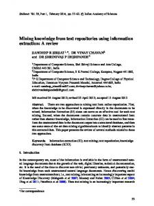
the execution trace exploration in various abstraction levels. Fischer et al. [39] used execution traces as clues for tracing the evolution of a software system. In [40] a heuristic exploration to execution traces has been proposed that aims at clustering the program functions based on their invocation frequency. Execution traces are also used in performance analysis of software systems. In [22, 36, 10] performance analysis of parallel systems is studied by using execution traces of the software systems. In [10, 36] a program’s execution trace is searched for certain predefined patterns that indicate inefficient behavior. In [12] a time interval analysis is applied to the execution traces to locate components that implement a certain feature in a distributed application. Traces of execution within the intervals with and without a specific feature being active are compared to locate the code component that implement that specific feature. N. Wilde et al. [35] proposed a set difference approach for locating software features in the source code, where the set of functions in the related scenario executions (those that execute a specific feature) are differentiated from scenario executions that do not invoke that specific feature in order to extract the specific feature’s functionality. In our approach, we also use the notion of feature specific scenarios, however we extract patterns of execution traces as evidences of the feature functionality. A major challenge in the trace-based dynamic analysis approaches would occur right at the beginning of the analysis, that is managing very large traces [20, 30, 39]. Hamou-Lhadj and Lethbridge [19] provide a framework to compress the execution traces by removing loop-based redundancies, where the process is reversible. The method is based on identifying identical sub-trees in the dynamic tree that is generated from an execution trace. We also use a similar technique to remove the loop-related redundancies. Reiss and Renieris [26] propose a set of trace compaction techniques including string compaction, dynamic call graph analysis, grammar-based encoding and finite state automata. Greevy and Ducasse [18] extract execution traces to generate a mapping between software features and classes by comparing the classes that generate the execution trace for different features. Our approach in this paper exploits an analysis technique to handle large sizes of the execution traces, and allows an intuitive and promising process of feature to component allocation that consequently leads us to measure the functional scattering and cohesiveness of the software structural units. 3. Proposed Framework Figure 1 illustrates different steps of the proposed framework for assigning software features onto its source code. The framework provides means for reducing the large sizes of execution traces, takes advantage of the relation discovery power of data mining and concept lattice analysis, and allows to measure the impact of individual features on the structure of the system. This process consists of four stages: Execution trace extraction; Execution pattern mining; Execution pattern analysis; and Structural evaluation. In the remaining of this section these stages are briefly 4
(Stage 2) Pattern Mining
(Stage 1) Trace Extraction
September 13, 2009 0:39 WSPC/INSTRUCTION FILE
Feature
Feature−Specific Scenario set Selection
Raw Entry−Exit Listing Pre−Processing Set of Execution Traces
Pattern Repository
New Scenario Set Selection
Feature−Specific Pattern
01 01 1 01 0 0 1 1 0 0 0 01 01 1 01 0 1 01 01 1 01 1 0
Scenario Set 1
Scenario−Set Traces
Common Pattern
(Stage 3 & 4) Pattern Analysis & Structural Evaluation
Scenario Execution on Instrumented System
jDynamic
0 1 1 0 0 1 0 1
0 11 0 0 1 0 1 0 01 1 0 01 1
Scenario Set 2
1 0 0 1 0 1 0 1 0 1 0 1
01 1 0 1 0 1 1 0 0 0 01 1 0 0 1 01 1 0 0 1 1
Execution Patterns
Execution Pattern Mining
Scenario Set 3
Second Pattern Generation All Execution Patterns Assigning Feature Functionality to System Modules
Concept Lattice Analysis
Measuring Feature Impact on System’s Structure
A family of relevant features (circle, ellipse, ...)
Fig. 1. Proposed framework for identifying the implementation of the functional aspects of a software system in the source code as a means to measure the structural impacts of different software features.
described. Stage 1. Execution trace extraction: important features of a software system are identified by investigating the system’s user manual, on-line help, similar systems in the corresponding application domain, and also user’s familiarity with the system. A set of relevant task scenarios are selected that examine a single software feature. We call this set of scenarios as feature-specific scenario set. For example, in the case of a drawing tool software system, a group of scenarios that share the “move” operation to move a figure on the computer screen would constitute such a featurespecific scenario set. In the next step, the software under study is instrumenteda to generate function names at the entrance and exit of a function execution. By running each feature-specific scenario against the instrumented software system a sequence of function invocations are generated in the form of entry/exit pairs. To make the large size of the generated traces manageable, in a pre-processing step we transform the extracted entry/exit listing into a sequence of function invocations and also remove all redundant function calls caused by the cycles of the program loops. The pruned execution traces are then fed into the execution pattern mining engine in the next stage. The pre-processing operation will be discussed in more details in Section 5.
a Instrumentation
refers to the process of inserting particular pieces of code into the software system (source code or binary image) to generate a trace of the software execution. 5
September 13, 2009 0:39 WSPC/INSTRUCTION FILE
jDynamic
Stage 2. Execution pattern mining: in this stage, we reveal the common sequences of function invocations that exist within the different executions of a program that correspond to a set of task scenarios. Each execution pattern is a candidate group of functions that implement a common feature within a scenario set. We apply a sequential pattern mining algorithm on the execution traces to discover such hidden execution patterns and store them in a pattern repository for further analysis. This stage will be discussed in more details in Section 6. Stage 3. Execution pattern analysis: even in one feature-specific scenario set, a large group of execution patterns are generated that must be organized and some must be filtered out to identify core functions of a feature. We employ two different mechanisms for this purpose: concept lattice analysis and second sequential pattern mining technique (the latter is not discussed in this paper). We use concept lattice analysis to cluster the group of functions in extracted patterns that exclusively correspond to a shared feature of a scenario set, and also to cluster the group of functions in patterns that are common to every scenario set. This stage is discussed in Section 7. Stage 4. Structural evaluation: in a further operation, by associating the featurespecific functions to the system’s structural modules (i.e., files of the system) two metrics are defined, namely structural cohesion and functional scattering that together provide a means for measuring the impact of individual features on the structure of the software system. 4. Formal definition of the approach In this section, we define the common terminology that we use throughout this paper to describe the execution pattern mining and pattern analysis aspects of the proposed approach. We use Z notation [37] to formally define the concepts in this section. In the Z notation, a “set” can be defined as {D | P • E} denoting a set of values consisting of all values of the term E for the declared variables in D that satisfy the constraint P . The predicate P and term E contain the free variables defined in D. For example, {x : N | x ≤ 5 • x2 } denotes the set {1, 4, 9, 16, 25}. The term E and its preceding “heavy dot” can be omitted which results {x : N | x ≤ 5} = {1, 2, 3, 4, 5}. The existential quantifier “∃” is used to define a new variable. The general form of the existential quantifier is ∃D | P • Q where D represents declarations, P represents a predicate acting as the constraint and Q represents the predicate being quantified. The constraint bar “|” and the constraining predicate P can be omitted, which results: ∃D • Q. The universal quantifier “∀” is used to define all variables that have certain properties. The general form of the universal quantifier is ∀D | P • Q. The constraint bar “|” and the constraining predicate P can be omitted, which results: ∀D • Q. 6
September 13, 2009 0:39 WSPC/INSTRUCTION FILE
jDynamic
• Feature φi corresponds to a single functionality (number i) that is provided by the subject software system; and Φ is the set of all available features. • Scenario sj is a sequence of features φi ∈ Φ; hence sj = [φj1 , φj2 , . . . , φjn ]. Also S is the set of all applicable scenarios on the system. • Feature-specific scenario set Sφi is a set of scenarios sj ’s that use specific feature φi ; such that Sφi = {sj | sj ∈ S ∧ φi ∈ sj }. In this model, the execution of a scenario sj on the subject software system is represented by a traversal of the software’s static call graph, where each tree traversal generates a dynamic call tree dctj that is defined below. • Let F be the set of all function names in the subject software system. • Dynamic Call Tree dctj =< F ′ , E > is a tree where the set of nodes F ′ represents different invocationsb of functions f ∈ F, and E ⊂ F ′ × F ′ represents the set of edges among function invocations. • Dynamic Software System Ψ models the subject software system as a set of all possible dynamic call trees dctj ’s that are generated by the execution of task scenarios sj ∈ S on the subject software system. We also model a scenario execution E(sj ) on the subject software system as a look up operation which returns the corresponding dynamic call tree of the scenario sj , hence E : S → Ψ. For simplicity and without loss of generality, we use Ψ to represent only dynamic call trees that correspond to a group of k feature-specific scenario S sets that are represented by “the restricted S” as S = i=[1..k] Sφi . This means the subject software system Ψ can only execute the intended k scenario sets, not all possible scenarios. • Preprocessor Π : Ψ → T is a tree pruning and serialization operation, where: i) replaces multiple instances of identical subtrees (i.e., repeated under a particular parent node) in a dynamic call tree dctj , with one of those instances; and ii) maps the loop-free dctj to an execution trace tj ∈ T using a depth first traversal operation on the dynamic tree dctj , where the sequence of visited nodes in this traversal constitute execution trace tj . In this form, T represents the set of all traces tj that are stored in a repository to be used for execution pattern generation process; and Tφi represents feature specific traces that correspond to scenario set Sφi . Hence: Tφi = {t | ∀sj ∈ Sφi • t = Π(E(sj ))} S T = i=[1..k] Tφi • Execution pattern px is defined as a subsequence of a trace t (i.e., a contiguous sequence of functions f within trace t) that is supportedc by at least b In
this context, two different invocations of a single function f ∈ F are represented as f i , f j ∈ F ′ (i 6= j). c p exists in certain number of execution traces t ’s, where the collection of t ’s are called the x j j 7
September 13, 2009 0:39 WSPC/INSTRUCTION FILE
jDynamic
M inSupport number of execution traces in T ; where the support of execution pattern px is defined below. Also, P is the set of all execution patterns px . sup(px , T ) = {t | t ∈ T ∧∃i ≥ 0 | ∀j (i ≤ j < (i+|px|) → px [j−i] = t[j])}. • Execution pattern miner Υ(T , n) is a function which receives the set of execution traces T and MinSupport n, and returns all execution patterns px ∈ P that exist in at least n execution traces t’s in T . Υ(T , n) = {p | subSeq(p, t) ∧ t ∈ T ∧ |sup(p, T )| ≥ n} ≡ P. Depending on the level that functions are participated in execution patterns of different feature-specific scenario sets, we define two categories of functions: featurespecific functions and common functions as follows. • Fφi is a set of feature-specific functions that are used to implement specific feature φi . Fφi = {f | f ∈ p ∧ p ∈ Υ(Tφi , n) ∧ n = |Sφi | } • Fcom is the set of common functions that exist in the extracted patterns of almost every feature-specific scenario set. Fcom = {f | f ∈ p ∧ p ∈ Υ(T , n) ∧ n ≈
P
i=[1..k]
|Sφi | }
Based on the above definitions, we present the details about different stages of the proposed dynamic analysis framework in Section 3. These activities are summarized below. (1) Execute k different feature-specific scenario sets Sφi (i ∈ [1..k]) on the subject software system and generate the corresponding dynamic call trees Ψ. (2) Preprocess the dynamic call trees in Ψ in order to eliminate the loop-based repetitions and generate feature specific execution traces Tφi (and consequently all execution traces T ). (3) Apply execution pattern miner on Tφi ’s (i ∈ [1..k]) to extract k sets of featurespecific patterns Υ(Tφi , n). (4) Apply concept lattice analysis on functions of different patterns in all Υ(Tφi , n)’s in order to separate feature-specific functions Fφi from common functions Fcom . (5) Finally, study the impact of the implemented features on the structure of the system. support of the pattern px . 8
September 13, 2009 0:39 WSPC/INSTRUCTION FILE
jDynamic
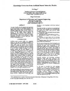
5. Execution trace extraction (stage 1) In order to run different scenario sets on the subject software system, we need to instrument the system. We adopt Aprobe [4] which is a binary level software instrumentation tool to insert patches, namely probes, within the binary image of the executable program. We use a pre-defined probe (namely trace) which generates text messages at both entrance and exit of each function. Consequently by running the selected feature-specific scenario sets we obtain entry/exit listings that are transformed into dynamic call trees in a further step. For space limitation this transformation is not discussed in this paper. This step that represents E : S → Ψ generates different groups of dynamic call trees corresponding to different scenario sets that should be pre-processed and converted to the execution traces for the execution pattern analysis. Pre-processing. The preprocessor Π : Ψ → T is a dynamic call tree pruning and trace serialization operation. Dynamic analysis of a medium size software system using execution traces can produce very large traces ranging to thousands or tens of thousands of function calls. This would be a main source of difficulty in a dynamic analysis. The effective trace of functions corresponding to a scenario execution is cluttered by a large number of function calls from operating system, initialization and termination operations, utilities, repetition of sequences caused by the loops, and also noise functions that are interleaved within a call sequence. In this work, we ignore recursive function traces and focus on pruning the loop-based redundancies. We transform the entry/exit listing that is generated by executing a task scenario on the software system into a dynamic call tree where nodes represent functions and edges represent function calls. Since each loop resides in the body of a function, the loops will form identical subtrees as the children of the parent function. We also assign an integer ID to each tree node, where roots of identical subtrees posses identical IDs. This technique significantly simplifies the task of localizing and eliminating the loop-based redundancies at proper children of each node in the dynamic call tree. Therefore, the loop redundancy removal problem is reduced to identification of identical subtrees that are repeated under a particular node. Figure 2(a) shows Procedure Foo that produces a long trace with repetitions of “F1, F2”. Figure 2(b) illustrates a small portion of a dynamic call tree that is generated from an execution of the Procedure Foo. Furthermore, each node in this dynamic call tree is annotated with its ID. Note that functions F1 and F2 are called several times by function Foo, hence they acquire different IDs depending on their run-time behavior. The pruning process is as follows: i) Generate a string representation of ID’s from different sibling subtrees. ii) Apply a repetitive string finder algorithm (Crochemore [11]) to transform the original string (with repetitions) into a new string with no repetitions. iii) In the new string, each group of repetitions is shown as one instance 9
September 13, 2009 0:39 WSPC/INSTRUCTION FILE
jDynamic
Foo
Procedure Foo begin .... Call F1; While condition do Call F1; Call F2; end .... end (a)
.. .
11F1
10F1
10F1 10 F1 10 F1
9 F2
8 F2
8F2
8F2
8F2
6 F3
7 F3
7 F3
7 F3
7F3
5F4 4F5
12 F20 13 F21
14 F22 15
(While loop) Repetitions are replaced by one sub−tree
. ..
.. .
F23
(b)
Fig. 2. (a) A dummy procedure which generates loop-based repetition. (b) Dynamic call tree generated from an execution of Procedure Foo.
. . ., Foo, F1, F1, F2, F1, F2, . . ., F1, F2, . . .
. . . , F oo, F 1, (F 1, F 2)n , . . .
. . . , F oo, (F 1)2 , (F 2, F 1)n−1 , F 2, . . .
(a)
(b)
(c)
Fig. 3. (a) A string containing repetitions. (b) Representation of (a) in the form of one instance of string repetition. (c) Another representation of (a) in the form of one instance of string repetition.
of the repetition that is labeled with the number of the repetitions. For example, in Figure 3(a) the string F1,F2,F1,F2, ..., F1, F2 is transformed into (F1,F2)n in Figure 3(b). There may exist more than one pattern of repetitions for a given string (e.g., strings in Figures 3(b) and (c)) and hence we apply the following heuristic in order to select the dominant pattern. The repetitive pattern with the highest power generates a pattern that is resulted from a program loop. As a result, we keep subtrees corresponding to a single instance of each loop which greatly reduces the complexity of the dynamic call tree. Finally, by traversing the loop-free dynamic call tree in a depth-first order and keeping the visited nodes in a sequence, a loop-free execution trace is generated. 6. Execution pattern mining (stage 2) In the data mining literature, sequential pattern mining is used to extract frequently occurring contiguous (or interleaved) sequences of events (known as patterns) among the sequences of customer transactions [7]. In the proposed approach, we use a modified version of the original sequential pattern mining algorithm by Agrawal [7], where an execution pattern is a contiguous part of an execution trace that is supported by M inSupport number of the execution traces. The execution pattern miner Υ(Tφi , n) receives different sets of pruned (loopfree) feature-specific execution traces Tφi as well as the MinSupport n for each set, and generates different sets of execution patterns containing both feature-specific functions Fφi and common patterns of functions Fcom . Figure 4(a) illustrates the application of pattern miner Υ(Tφi , n) on three sets of 10
September 13, 2009 0:39 WSPC/INSTRUCTION FILE
jDynamic
execution patterns F3, F8, F9, F12 F8, F9, F12 F9, F12 F3
F12
F9
F8
F8
F12
F9
SubPattern F9 F12 F12
SubPattern
Execution pattern
F1 & F15 F4, F10
& F18, F20 (a)
(b)
Fig. 4. (a) Feature specific scenario sets and their corresponding execution patterns. (b) An execution pattern along with its redundant sub-patterns; a trie structure is used to eliminate subpatterns during the execution pattern generation.
feature-specific execution traces. As a result, feature-specific and common patterns are extracted. The noise execution patterns in Figure 4(a) are a kind of common patterns that are not as frequent as common patterns, and hence are not as important as the two main types of patterns. Each feature-specific pattern only exists in its corresponding traces; common patterns almost exist everywhere; and noise patterns, are those whose frequencies are in the middle. In this example, the functions that implement each feature are highlighted; also the separation of different types of patterns is trivially feasible for human. However, for large trace sizes a large number of patterns of different types are generated whose separation is almost impossible by human’s inspection. The pattern miner generates a large number of execution patterns such that the majority of these patterns are redundant sub-patterns of a large execution pattern and cause size explosion that significantly increase the computational complexity. In order to identify and eliminate the sub-patterns of a final execution pattern, we use a Trie data structured and annotate its nodes with the function names. Figure 4(b) illustrates a Trie data structure that we use for representing the trace of pattern functions. Each leaf Trie node can be labeled as final (i.e., an execution pattern) or subpattern (a redundant pattern) where the latter will be eliminated. In doing so, the sequence of functions in each execution pattern px is stored along a path from the root to the leaf of the Trie, and the corresponding leaf is marked “final” if the sequence does not already exist in the Trie. 7. Execution pattern analysis (stage 3) We employ a strategy to focus on execution patterns corresponding to a specific feature within each group of scenario set as well as common patterns that exist in dA
Trie is a binary search tree data structure that stores the information about the contents of each node in the path from the root to the node. 11
September 13, 2009 0:39 WSPC/INSTRUCTION FILE
jDynamic
Objects (as s/w features)
f1
Attributes (as s/w functions)
s1
f1
f2
X
X
s2
X
s3
X
f3
f4
f5
f2
c2=
X
X
X
f3
f4
f5
fi Attribute
s3
s2
s1
s i Object
X
Subconcept Relation
(a) Context Table
(b) Concept Lattice
Cx
< Ext(Cx), Int(Cx)>
C1 C2 C3 C4 C5
< {s1, s2, s3}, {f1} > < {s1, s2}, {f1, f2} > < {s1}, {f1, f2, f5} > < {s2}, {f1, f2, f4} > < {s3}, {f1, f3} >
(c) Concepts from Lattice
Fig. 5. Three steps to identify the concepts from a relation.
almost all scenario sets. In the following, the different kinds of functions that exist in extracted execution patterns along with the corresponding extraction mechanisms are presented. Feature-specific functions Fφi . Feature-specific functions are core functions that implement the targeted feature φi of a feature-specific scenario set Sφi . In order to extract feature-specific functions, we should increase the level of MinSupport n of the pattern miner Υ(Tφi , n) to a number that covers the majority of the scenarios in Sφi . Common functions Fcom . Common functions exist in almost every task scenario of the software system, e.g., software initialization / termination operations, or mouse tracking. Such functions exist in every execution trace of every scenarioset Sφi . Therefore, it is extracted along with the feature-specific function mentioned above. Given a group of two or more feature-specific scenario sets, each with a different specific feature, the extracted execution patterns which are shared among the majority of the scenarios implement the common features of the software system. In order to extract such functions, we should use a filtering mechanism such as concept lattice analysis to filter out the feature-specific functions from this group of functions. Although each of the above categories may be required in a particular analysis task, the first category reveals the implementation of the feature that is targeted by the set of task scenarios and hence is considered as the more relevant type of dynamic analysis. In the rest of this section, we present a filtering mechanisms to separate the common functions from feature-specific functions. 7.1. Concept Lattice Analysis We employ the visualization power of mathematical concept analysis (Birkhoff 1940 [9] and Ganter & Rudolf 1999 [17]) as a strategy to cluster the group of functions in execution patterns that either: i) exclusively correspond to a shared feature of a scenario set; or ii) shared among all scenario sets. A formal context is defined as a triple C = (O, A, R) which represents the relation R between objects O and their 12
September 13, 2009 0:39 WSPC/INSTRUCTION FILE
jDynamic
attribute values A. A concept cx is a maximal collection of objects sharing maximal common attribute-values. Figure 5 illustrates three steps for defining the set of concepts: (a) context table among objects and their attributes, where maximum groups of shared features among objects can be identified as maximum group of X’s; (b) concept lattice, where each node represents a concept cx ; and (c) the list of concepts, where each concept cx is represented by as a tuple of extent “Ext(cx )” and intent “Int(cx )”. A concept lattice has the following characteristics: • Each lattice node (i.e., a concept) may have labels for objects and attributes. • Every object has all attributes that are defined at that node or above it in the lattice (directly above or separated by some links). • Every attribute exists in all objects that are defined at that node and below it in the lattice (directly below or separated by some links). In our approach, we present the relation R′ between “set of features Φ” and “set of functions F ” such that C = (Φ, F , R′ ). In other words, an object is a targeted feature φi ∈ Φ of a feature-specific scenario set Sφi , and an attribute is a function f that participates in the execution patterns corresponding to Sφi . Applying concept lattice analysis to the proposed formal context will result in separation of “featurespecific functions Fφi ” from “common functions Fcom ” as follows. A concept lattice can be used to collect the set of shared attributes contained in a set of objects such that the shared attributes appear in the nodes that are located in the upper region of the lattice. Consequently, the nodes in the lower region of the lattice collect the attributes that are specific to the individual objects in that region. We exploit this property to group functions of the extracted execution patterns. In our case, common functions Fcom are executed through almost every task scenario of the software system; hence these functions cluster in upper region of the lattice. However, this property also prevents us from distinguishing different groups of functions that implement different common functionality. On the other hand, feature-specific functions Fφi are located in the lower region of the lattice. Consequently, functionality of these functions can be easily identified using the meaning of the specific feature of the corresponding lattice node. Particularly, a concept whose extent consists of a single object (feature φi ) collects all functions that exclusively implement that feature. 8. Structural Evaluation of Software System Software systems are continuously evolving throughout their life time from early development to their maintenance and retirement. During the maintenance phase the software system is still changing through activities such as bug-fixing, migration to new platforms, and adding new features which were not planned from the beginning. Therefore, even a nicely designed and accurately implemented software system will probably incur several changes to its functionality and consequently to its structural design. This common scenario is the main cause of structural dam13
September 13, 2009 0:39 WSPC/INSTRUCTION FILE
jDynamic
age, high maintenance cost, and eventually retirement of a legacy system. To help this situation, the task of the software maintainers is to measure the impair on the structure of the software system and assess the current state of the resulting legacy system. One approach to address this problem is to assess the structural merit of the software system based on the degree of functional scattering of software features among the structural modules. In this context, the functionality of the system is represented as a set of features that are implemented within the software modules and are manifested as constituents of different scenarios to be run on the software system. In addition, the functional cohesion of each system module can also be investigated as a means to monitor the healthiness of the software system. In this section, we provide two metrics to assess the structural merit of the software system, namely: functional scattering and structural cohesion. The proposed functional scattering metric examines the distribution of a set of functions that implement a family of relevant features (could consists of one single feature) over the structural units (i.e., files) of the system. Hence, it represents the degree of scattering of the implementation of software features among the structural modules. On the other hand, the structural cohesion assessment directly represents the cohesion of module(s) implementing a specific feature based on the functional relatedness of the functions that reside in each structural unit (module). This measure of cohesion is much closer to the original definition of cohesion (“relative function strength of a module” [24]) than using static structural techniques such as inter-/intra-edge connectivity of the components. A feature family Φi (also denoted as a logical module) is a set of related features that posses similar functionality with regard to a single feature φi , i.e., they share feature-specific functions from Fφi . In order to measure the functional scattering of a logical module Φi , we assess the level of distribution of the functions that correspond to Φi (denoted as FΦi ) over the whole structure of the relevant system files. Similarly, we compute the structural cohesion of a system file as the level of relatedness of its functions with respect to the functions in a logical module i.e., FΦi . To obtain these metrics, first we identify and collect the functions of the logical module using the above discussed concept lattice analysis. Then, the source files that contain these functions are identified and the ratio of shared functions over the total functions are calculated as follows. • Let Fl be the set of functions that are defined in file l. • Let LΦi = {l1 , l2 , . . . , lk } be the set of system files that contain all functions of the logical module Φi (i.e., FΦi ). • Structural cohesion of file l with respect to logical module (feature family) Φi is defined as: |Fl ∩ FΦi | SCΦi (l) = |Fl | • Functional scattering of logical module (feature family) Φi is defined based on 14
September 13, 2009 0:39 WSPC/INSTRUCTION FILE
jDynamic
Common Functions
Copy Family
Spline Family
Ellipse Family
(a)
(b)
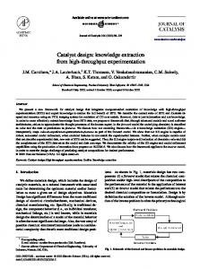
Fig. 6. (a) Feature-specific scenario-set. The group of scenarios apply the “Flip” operation on different graphical objects. (b) Concept lattice representation of the extracted features and their corresponding functions for the Xfig drawing tool. The group of concepts (and their functions) corresponding to three feature families and the common functions are shown by dashed ovals.
the distribution of functions in FΦi over files in LΦi as: P l∈LΦi SCΦi (l) FS(Φi ) = 1 − |LΦi | A software system with high structural cohesion SCΦi (l) for its individual files and low functional scattering FS(Φi ) among its files represents a modular system that requires low maintenance effort. However, a high degree of functional scattering corresponding to a feature family Φi directly signifies a high structural impair that is caused by that feature family. Hence the system requires more maintenance effort to tackle with the consequences of propagated change to other software files. 9. Experiments In this section, we apply the proposed dynamic analysis technique on two mediumsize open source systems. The developed dynamic analysis tool is an Eclipse plug-in [2] and has been developed as an extension to the Alborz reverse engineering toolkit [31] to enhance the scope of Alborz to cover both static and dynamic analysis of a software system. 9.1. Dynamic Analysis of Xfig Xfig 3.2.3d [1] is an open source, medium-size (80 KLOC), menu driven, C language drawing tool under X Window system. Xfig has the ability to interactively draw 15
September 13, 2009 0:39 WSPC/INSTRUCTION FILE
jDynamic
and manipulate graphical objects (circle, ellipse, line, spline, rectangle, and polygon) through operations such as copy, move, delete, edit, scale, and rotate. In the following we discuss application of the proposed dynamic analysis technique on the Xfig drawing system, according to the stages of the proposed framework in Section 3. Figure 6(a) illustrates the group of task scenarios that form a feature specific scenario set, where the flip operation is the specific feature. In this setting, a group of seven scenarios have been selected that all begin from the start up operation and finish in the terminate operation. Each scenario has a distinct path within the Drawing component, but shares the same path (i.e., flip operation) within the Editing component. We apply the above strategy to generate feature-specific scenario sets that each target one feature within Figure 7. We execute the scenarios of each feature-specific scenario set Sφi on the instrumented Xfig system and obtain the corresponding entry/exit listings. After pruning the extracted entry/exit listings from loop-based function calls we apply the execution pattern mining process to obtain the patterns of function call sequences. Figure 7 presents the statistics about attributes of a group of feature-specific scenario sets that we used in analyzing Xfig. This table illustrates a major characteristic of the proposed dynamic analysis with regard to reducing the scope of the analysis from huge sizes of the execution traces (Average Trace Size) to the manageable sizes of the execution patterns (Average Pattern Size). Concept Lattice Analysis. We supply the resulting execution patterns of the Xfig experiments to a concept lattice generation tool (concept explorer [3]) in order to view the distribution of the feature functions on the lattice. As it was discussed in Section 7.1 the feature-specific functions are clustered around the nodes (concepts) that each represent a specific feature. Similarly, the common function that are shared among a majority of concepts are clustered at the upper region of the lattice, and hence their common operations can not be distinguished from each other. The visualization power of the concept lattice will also allow us to cluster the group the functions of highly related features (i.e., lower region lattice nodes) into feature families where they present similar behaviors. In Figure 6(b) three dashed circles at the bottom illustrate the group of concepts and their functions that implement the core functionality of the feature families of ellipse, copy, and spline. On the other hand, the upper nodes collect those functions of Xfig corresponding to common patterns, such as: software initialization and termination, mouse pointer handling, canvas view updating, and side ruler management. Structural Evaluation. Based on inspecting the source files of Xfig, we measure the structural cohesion of corresponding source files, as well as the functionality scattering of the feature families under study. The results of this evaluation for three feature families Draw Ellipse, Copy, and Draw Spline are presented in Figure 8. For the three mentioned feature families we inspect the Xfig source files that
16
September 13, 2009 0:39 WSPC/INSTRUCTION FILE
Feature Family Draw Ellipse
Specific Feature of Xfig Circle-Diameter Circle-Radius Ellipse-Diameter Ellipse-Radius
jDynamic
# Different Scenarios 10 10 10 10
Average Trace Size 7234 8143 6405 7351
Avg Pruned Trace Size 2600 2463 2536 2549
# Extracted Patterns 46 48 41 39
Average Pattern Size 33 32 37 35
4 4
11887 11460
3166 3269
31 37
53 50
10 10 10
18635 15469 15057
4434 4038 5362
58 66 61
63 49 47
Copy
Move Objects Copy Objects
Draw Spline
Closed Interpolated Interpolated Approximated
Scale
Center Scale
4
8088
1541
30
47
Flip
Flip up-Right
4
7296
1378
29
46
Rotate
Rotate Clockwise
4
6974
1544
28
44
Delete
Delete Objects
4
6580
1181
19
56
Fig. 7. The result of execution trace extraction and execution pattern mining for a collection of Xfig feature families and their specific features.
define the functions that implement the corresponding logical module FΦi of that feature family. The results of measuring the structural cohesion SCΦi (l) of these files are presented in Figure 8. These results indicate that file d ellipse has high cohesion with respect to logical module of feature family Ellipse; files e copy, and e move are also highly cohesive with respect to feature family Copy; and finally, file d spline is cohesive with respect to feature family Spline. However, study of the functional scattering measures allows us to better interpret the characteristics of these logical modules. For example, in the case of Ellipse a small portion of the logical module FΦi is located in a large file u elastic which results in a high functional scattering measure. Whereas, in the case of Copy feature family, the logical module almost covers two files e copy and e move which indicates low scattering. In the case of Spline, the logical module is almost equally scattered among four files each covering a small portion of the files and hence indicating high functional scattering. We also adopt a minimum threshold value of 10% in order to consider a file in the calculation of the above measurements. The results in Figure 8 are promising in the sense that they reflect meaningful measures with respect to the sizes of logical modules and system files shown. Regarding the results of our structural evaluations, we can predict high maintenance activities regarding any change to the feature families Ellipse and Spline. However, changes to the Copy feature family would not propagate throughout the system which indicates less maintenance activity is required. 9.2. Dynamic Analysis of Pine Email Client Pine 4.4.0 [6] is an open source, large-size (207 KLOC), C language email client for reading, sending, and managing electronic messages. For this case study, we repeated exactly the same steps we discussed in the study of the Xfig drawing tool. We examined 4 different features of Pine for: composing emails, managing the folder lists, address book, and message index. Figure 9 presents the result of execution traces extraction as well as execution pattern mining for the above 4 Pine features. By repeating this process and targeting other features of the system with 17
September 13, 2009 0:39 WSPC/INSTRUCTION FILE
Feature Family Φi
Contributed File (l)
Ellipse
d ellipse.c u elastic.c
Copy
e copy.c e move.c
Spline
d d u u
line.c spline.c bound.c draw.c
jDynamic
|Fl |
|Fl ∩ FΦ | i
16 67
12 8
Structural Cohesion SCΦ (l) i 75% 12%
Functional Scattering FS(Φi )
5 4
3 3
60% 75%
32%
9 6 19 75
2 5 2 14
22% 83% 11% 19%
66%
57%
Fig. 8. Structural cohesion and functional scattering measures for three different feature families of the Xfig (the threshold value for this calculations are chosen as 10%).
Specific Feature of Pine Compose Folder List Message Index Address Book
# Different Scenarios 8 4 5 3
Average Trace Size 90081 48335 67741 59221
Average Pruned Trace Size 24636 11205 19529 16024
Number of Extracted Patterns 95 25 44 71
Average Pattern Size 172 491 345 212
Fig. 9. The result of execution trace extraction and execution pattern mining for a collection of 4 different Pine features. Feature Family
Contributed
Φi
File (l)
Compose
context.c bldaddr.c send.c reply.c
Folder List
folder.c
Address Book
adrbklib.c addrbook.c
Message Index
pine/mailview.c
|Fl |
|Fl ∩ FΦ | i
Structural Cohesion
Functional Scattering FS(Φi )
88%
13 78 99 65
2 9 57 12
SCΦ (l) i 16% 12% 56% 19%
121
15
12%
88 75
12 20
14% 27%
80%
126
21
17%
83%
74%
Fig. 10. Structural cohesion and feature functional scattering measures for four different features the Pine email client (the threshold value for this calculations are chosen as 10%).
proper sets of scenarios, we could incrementally explore the Pine system’s overall functionality. By spreading the extracted execution patterns over a concept lattice we could separate feature-specific functions from common functions that implement experimented features. Finally, based on inspecting the source code of Pine, we measured the distribution of functions that implement each examined feature over the structural units. The results are shown in Figure 10. For each feature family Φi in Figure 9 we inspected the Pine source files that define the functions that implement the corresponding logical module FΦi of that feature family. The results of measuring the structural cohesion SCΦi (l) of these files are presented in Figure 10. These results indicate high degree of scattering among the examined feature families of Pine. Files context, bldaddr, and reply have low cohesion with respect to logical module of feature family Compose; file send shows high cohesion with respect to feature family Compose. However, study of the functional scattering measures allows us to better interpret the characteristics of these logical modules. For example, in the case of Compose a portion of the logical module FΦi is located in a large file send which results in a high functional scattering 18
September 13, 2009 0:39 WSPC/INSTRUCTION FILE
jDynamic
measure. 10. Conclusion and Future Work In this work, we proposed a novel approach to dynamic analysis and structural assessment of a software system that takes advantage of repeated patterns of execution traces that exist within the executions of a set of carefully designed task scenarios. The proposed approach takes advantage of techniques such as: execution trace manipulation; sequential pattern mining; string processing; and software visualization through concept lattice analysis. This work benefits from the discovery nature of data mining techniques and concept lattice analysis to extract both feature specific and common groups of functions that implement important features of a software system. The resulting execution patterns provide discovery of valuable information out of noisy execution traces. This technique is centered around a set of task scenarios that share a specific system feature. The whole process consists of several steps such as: software instrumentation; feature-specific scenario set selection; loop-based execution trace elimination; execution pattern extraction; and finally structural assessment of the software system. The proposed technique has been applied on two medium size systems: an interactive drawing tool, and an email client with very promising results in extracting both feature specific and common functions. Moreover, the level of “structural cohesion” and “functional scattering” are measured that provide a way for assessing the structure of the experimented system. More specifically, the contributions of this work to the field of software maintenance can be categorized as follows. • Devised a novel pattern based approach to dynamic analysis of a software system that employs data mining techniques to extract valuable information out of noisy execution traces. • Proposed a technique to reduce the large sizes of the execution traces by eliminating the loop-based repetitions. • Proposed a new technique for eliminating the sub-patterns that are generated along with the execution patterns. • Identified the set of core functions that implement specific features as well as common features of software systems. • Provided a measure of scattering the feature functionality over the software structure and a measure of module cohesion. • Visualized the distribution of functions over specific features using concept lattice analysis. • Implemented a publicly available Eclipse plug-in toolkit (Dynamic Alborz) for dynamic analysis [5]. The proposed dynamic analysis in this paper has been the foundation for our current research on the hybrid static and dynamic approaches, through: embedding run-time profiling information into a pattern-based architecture recovery technique 19
September 13, 2009 0:39 WSPC/INSTRUCTION FILE
jDynamic
to control component interactions [28]; and a multi-view architecture recovery where the structure view is reconstructed using modules and interconnections that are resulted by growing the core functions related to the specific feature identification in source code [29]. Currently, we are pursuing the integration of dynamic analysis with a two-phase design pattern recovery technique, and we intend to apply the proposed execution pattern mining towards identifying interaction patterns among web-based distributed systems. References [1] Xfig version 3.2.3. http://www.xfig.org/. [2] Eclipse version 3.0. http://www.eclipse.org. [3] Formal concept analysis toolkit version 1.0.1. http://sourceforge.net/projects/conexp. [4] Aprobe 4.2 for Windows: Software Instrumentation Tool, URL = http://www.ocsystems.com/. [5] Dynamic Alborz, a Toolkit for Dynamic Analysis of Software Systems. URL = http://www.cas.mcmaster.ca/∼sartipi/Alborz/dynamic/. [6] Pine Email Client Version 4.4.0, URL = http://www.washington.edu/pine/. [7] R. Agrawal and R. Srikant. Mining sequential patterns. In ICDE ’95: Proceedings of the Eleventh International Conference on Data Engineering, pages 3–14, Washington, DC, USA, 1995. IEEE Computer Society. [8] T. Bell. The concept of dynamic analysis. In ESEC/FSE-7: Proceedings of the 7th European software engineering conference held jointly with the 7th ACM SIGSOFT international symposium on Foundations of software engineering, pages 216–234, London, UK, 1999. Springer-Verlag. [9] G. Birkhoff. Lattice Theory. American Mathematical Society, 1st edition, 1940. [10] H. W. Cain, B. P. Miller, and B. J. N. Wylie. A callgraph-based search strategy for automated performance diagnosis (distinguished paper). Lecture Notes in Computer Science, 1900:108+, 2001. [11] M. Crochemore. An optimal algorithm for computing the repetitions in a word. Inf. Process. Lett., 12(5):244–250, 1981. [12] D. Edwards, S. Simmons, and N. Wilde. An approach to feature location in distributed systems. Technical report, Software Engineering Research Center (SERC), 2004. [13] T. Eisenbarth, R. Koschke, and D. Simon. Derivation of feature component maps by means of concept analysis. Fifth European Conference on Software Maintenance and Reengineering, March 2001. [14] T. Eisenbarth, R. Koschke, and D. Simon. Locating features in source code. IEEE Transactions on Software Engineering, 29:210 – 224, March 2003. [15] M. El-Ramly, E. Stroulia, and P. Sorenson. Recovering software requirements from system-user interaction traces. In SEKE ’02: Proceedings of the 14th international conference on Software engineering and knowledge engineering, pages 447–454, New York, NY, USA, 2002. ACM Press. [16] M. Ernst. Static and dynamic analysis: synergy and duality. In ICSE Workshop on Dynamic Analysis (WODA), Portland, Oregon, USA, May 2003., 2003. [17] B. Ganter and R. Wille. Formal Concept Analysis: Mathematical Foundations. Springer Verla, 1999. [18] O. Greevy and S. Ducasse. Correlating features and code using a compact two20
September 13, 2009 0:39 WSPC/INSTRUCTION FILE
[19]
[20] [21]
[22]
[23]
[24] [25]
[26] [27]
[28]
[29]
[30]
[31] [32] [33] [34] [35] [36] [37] [38]
jDynamic
sided trace analysis approach. In European Conference on Software Maintenance and Reengineering (CSMR’05), pages 314–323, 2005. A. Hamou-Lhadj, T. Lethbridge, and F. Lianjiang. Compression techniques to simplify the analysis of large execution traces. In IEEE International Workshop on Program Comprehension (IWPC’02), pages 159–168, 2002. A. Hamou-Lhadj, T. Lethbridge, and F. Lianjiang. Challenges and requirements for an effective trace exploration tool. In IWPC’04, pages 70–78, 2005. C. Lindig and G. Snelting. Assessing modular structure of legacy code based on mathematical concept analysis. In Proceedings of the 19th International Conference on Software Engineering, pages 349–359, 1997. B. Nikhil, M. Shirley, W. Felix, D. Jack, and M. Bernd. A pattern-based approach to automated application performance analysis. Proceedings of the Workshop on Patterns in High Performance Computing (patHPC 2005), 2005. W. D. Pauw, D. Lorenz, J. Vlissides, and M. Wegman. Execution patterns in objectoriented visualization. In Proceedings Conference on Object-Oriented Technologies and Systems (COOTS ’98), pages 219–234. USENIX, 1998. R. S. Pressman. Software Engineering, A Practitioner Approach. McGraw-Hill, third edition, 1992. E. Putrycz. Using trace analysis for improving performance in cots systems. In CASCON ’04: Proceedings of the 2004 conference of the Centre for Advanced Studies on Collaborative research, pages 68–80. IBM Press, 2004. S. P. Reiss and M. Renieris. Encoding program executions. In International Conference on Software Engineering (ICSE’01), pages 221–230, 2001. T. Richner and phane Ducasse. Recovering high-level views of object-oriented applications from static and dynamic information. In ICSM ’99: Proceedings of the IEEE International Conference on Software Maintenance, page 13, Washington, DC, USA, 1999. IEEE Computer Society. K. Sartipi and N. Dezhkam. An amalgamated dynamic and static architecture reconstruction framework to control component interactions. In IEEE International Conference on Reverse Engineering (WCRE 2007), pages 259–268, 2007. K. Sartipi, N. Dezhkam, and H. Safyallah. An orchestrated multi-view software architecture reconstruction environment. In Proceedings of IEEE WCRE’06, pages 61–70, October 2006. K. Sartipi and H. Safyallah. Application of execution pattern mining and concept lattice analysis on software structure evaluation. In Proceedings of the SEKE’06, pages 302–308, June 2006. K. Sartipi, L. Ye, and H. Safyallah. Alborz: An interactive toolkit to extract static and dynamic views of a software system. In ICPC’06, pages 256–259, 2006. M. Siff and T. Reps. Identifying modules via concept analysis. IEEE Transactions on Software Engineering, 25(6):749–768, Nov./Dec. 1999. P. Tonella and M. Ceccato. Aspect mining through the formal concept analysis of execution traces. A. van Deursen and T. Kuipers. Identifying objects using cluster and concept analysis. In Proceedings of the ICSE 1999, pages 246–255, 1999. N. Wilde and M. C. Scully. Software reconnaissance: mapping program features to code. Journal of Software Maintenance, 7(1):49–62, 1995. F. Wolf, B. Mohr, J. Dongarra, and S. Moore. Efficient pattern search in large traces through successive refinement. Pisa, Italy, 2004. Springer-Verlag. J. B. Wordsworth. Software Development with Z. Addison-Wesley, 1992. A. Zaidman, T. Calders, S. Demeyer, and J. Paredaens. Applying webmining tech-
21
September 13, 2009 0:39 WSPC/INSTRUCTION FILE
jDynamic
niques to execution traces to support the program comprehension process. In CSMR ’05: Proceedings of the Ninth European Conference on Software Maintenance and Reengineering (CSMR’05), pages 134–142, Washington, DC, USA, 2005. IEEE Computer Society. [39] A. Zaidman and S. Demeyer. Managing trace data volume through a heuristical clustering process based on event execution frequenc. In European Conference on Software Maintenance and Reengineering (CSMR’04), pages 329–338, 2004. [40] A. Zaidman and S. Demeyer. Managing trace data volume through a heuristical clustering process based on event execution frequency. In CSMR ’04: Proceedings of the Eighth Euromicro Working Conference on Software Maintenance and Reengineering (CSMR’04), page 329, Washington, DC, USA, 2004. IEEE Computer Society.
22