Abstract: - Traditionally, dynamic parameters of induction motors can be roughly estimated through conventional tests (no load test, block rotor test and ...
Proceedings of the 6th WSEAS International Conference on Power Systems, Lisbon, Portugal, September 22-24, 2006
108
Dynamic Model Identification of Induction Motors using Intelligent Search Techniques with taking Core Loss into Account BOONRUANG MARUNGSRI*, NITTAYA MEEBOON and ANANT OONSIVILAI Electrical and Energy Systems Research Unit, School of Electrical Engineering Suranaree University of Technology Nakhon Ratchasima, 30000 THAILAND Abstract: - Traditionally, dynamic parameters of induction motors can be roughly estimated through conventional tests (no load test, block rotor test and retardation test) and core loss is neglected in the dynamic behaviours analysis. Due to the complication of dynamic behaviours of induction motors, inaccuracy of transient characteristics may obtain when using these dynamic parameters. In order to improving accuracy of dynamic behaviour analysis, however, the inclusion of core loss in the machine model needs to be re-addressed and an intelligent approach to estimated dynamic parameters needs to be adopted. In this paper, three of intelligent search techniques, which are i) Tabu Search (TS), ii) Adaptive Tabu Search (ATS) and iii) Genetic Algorithm (GA), are employed to demonstrate the effectiveness of intelligent identification compared with the conventional model with and without core loss parameter(RC). The simulation results from dynamic parameters including RC obtained by the GA in comparison with the experimental results are convinced the effectiveness for this aim.
Key-Words: - Induction Motor, Dynamic Model, Intelligent Search, Core Loss, Tabu Search, Adaptive Tabu Search, Genetic Algorithm.
1 Introduction Induction motors are very commonly used in industrial applications over half a century because there are cheap, robust efficient and reliable [1]. Traditionally, the conventional steady state perphase equivalent circuit has been used to describing steady-state behaviours of three-phase induction motors [1–5]. Furthermore, in simple control, where the accuracy and the precision are not that much significant, such a steady-state model seems to be moderate for describing and represent the dynamic behaviour of induction motors. It is well known that only the standard steady-state per-phase equivalent circuit for three-phase induction motors has included core loss parameter in a simple and effective manner. But the generalized theory of machines neglects core loss parameter in the transient analysis of induction motors. Presently, however, with the development to complication and high accuracy controlled drive systems of induction motors, dynamic model from traditional steady-state parameters is not enough to represent the exactly dynamic behaviors of induction motor in high accuracy vector controlled
drives systems. Thus, the accurate parameter identification of induction motors is challenged for those controlled drives system. Many identification techniques have been studied and have been proposed for dynamic parameter identification of induction motors [6–11]. But there is still lack to include the effect of core loss in dynamic model. However, there has been increasing studied in the detuning effect of that the core loss produces [12– 20]. Hence, the effect of core loss should be taken into account and core loss parameter should be readdressed in dynamic model of induction motors. In this paper, the authors have proposed two kinds of dynamic model of induction motor. One is the dynamic model without core loss taking in to account. The other one is with core loss taking into account. And this paper also presents the effectiveness of intelligent search techniques, Tabu Search (TS), Adaptive Tabu Search (ATS) and Genetic Algorithm (GA) techniques, for identifying dynamic parameter of induction motors compared with the conventional techniques (no-load, lockedrotor and retardation tests). The validity of the authors aim is verified by stator current response
Proceedings of the 6th WSEAS International Conference on Power Systems, Lisbon, Portugal, September 22-24, 2006
and speed response from the simulation and the experimental results.
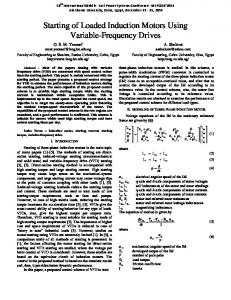
2 Equivalent Circuit and Modelling of Three Phase Induction Motors Traditionally, the steady state model of a three phase induction motor is represeted by the per phase equivalent circuit, including RC, where RC represents the equivalent resistance for core loss [2,3]. The steady state per phase equivalent circuit referred to the stator side of a three phase induction motor, neglecting and including RC, is given in Fig. 1.
Lmp vs Rs +Ls p is 0 = L p − jω L R +L p − jω L ⋅i r m r r r r r m
109
(2)
Where Ls = Lls + Lm, Lr = Llr + Lm and in the steady state p = jωs. The direct and quadrature axis model(d-q model) based on the space phasor theory is widely used for simulation the dynamic behaviour of three-phase induction motors as shown in Fig. 2. iqs
IS
RS
jXls
VS
Im
RC
jXlr
vqs
Ir
jXm
Rr/s
ωr iqr vqr
a) With RC included IS VS
RS
jXls
Im
jXlr
jXm
Ir
Idr
Rr/s
Vdr
Ids Vds
Fig. 2 d-q Axis Representation of Induction Motor. b) With RC neglected Fig. 1 Per Phase Equivalent Circuit of Three Phase Induction Motors.
The generalized theory of machine neglects core loss in the transient analysis of induction motors. From Equation (2) and from Fig. 2, neglecting RC and with vdr = vqr = 0, the following equations can be obtained.
As shown in Fig. 1, Vs is the stator phase voltage; Rs and Rr are the stator and rotor winding resistances; Xls and Xlr are the stator and rotor leakage reactance. Xm is the magnetizing reactance; and Rc is the equivalent resistance for core loss.
0 Lmp 0 iqs vqs Rs +LSp v 0 Rs +LSp 0 Lmp ids (3) ds = ⋅ 0 L p − ω L R + L p − ω L m r m r r r r i qr 0 ωL Lmp ωr Lr Rr +Lr p idr r m
From Fig. 1a, with power being supplied only on the stator side, the voltages and currents can be related as:
Where ωr is the rotor speed in electrical radians/sec. To represent RC in the d-q model, Equation (3) should be modified and be written to include RC in the d-q model as:
Kp vs Rs + Xp is 0 = Kp− jω K R + Yp− jω Y⋅ i (1) r r r r R CL m Where p = d/dt, K = R C + L m p , X = L 1s + K and Y = L 1 r + K .
From Fig. 1b, the relation between the input stator voltage and the stator and rotor currents can be derived as:
Kp 0 i qs vqs Rs + Xp 0 v 0 Rs + Xp 0 Kp i ds ds = ⋅ 0 Kp −ωr K Rr + Yp −ωr Y i qr Kp ωr Y Rr + Yp i dr 0 ωr K
(4)
The voltage equations are valid under both transient and steady state condition. In order to prove the authors aim, the state equations in the stationary reference frame are chosen. Under transient
Proceedings of the 6th WSEAS International Conference on Power Systems, Lisbon, Portugal, September 22-24, 2006
conditions, the equation of motion as functions of stator currents, rotor currents and rotor speed as shown in equation (5) is used to simulate the speed response compared with the experimental results.
Table 1 Induction Motor Parameters from the Conventional Tests. Induction Motor Parameters 74.02 Rls (Ω) 62.01 Rlr (Ω) 0.6482 Rc (Ω) Lls (H) 0.2087 Llr (H) 0.2087 Lms H) 3.4377 Bm(N.m.s/rad) 0.0000 Jm(N.m.s2/rad) 0.0025
(5)
In this paper, transient condition is starting process of induction motor from standstill to full speed at no load ( TL = 0 ).
3 Experimental Results
3
Experimental Result 2 Current, A
Where
dω J m dt r = ( Tem − TL ) + B m ω r Tem = − 23 PL m ( i ds i qr − i qs i dr ) , J m = Moment of inertia B m = Friction coefficient TL = Load torque
1 0
-1
A squirrel-cage induction motor, 0.5-kW, 220/380V, 50-Hz, 3-phase, is used for the conventional tests as shown in Fig. 4.
-2
Simulation Result
-3 0
0.05
0. 1
0.15
Digital Oscilloscope 3 Phase
0.3
0.35
0 .4
2000
Induction Motor
Pendulum Machine
Control Unit for Pendulum Machine
Block Diagram Representing the Experimental Set.
With the conventional no-load, locked-rotor and retardation tests, the parameters of the induction motor can be obtained. They are put in Table 1. These parameters are used to simulate the stator current and the speed responses compared with the results from experimental test. The comparison results are shown in Fig. 5. As shown in Fig. 5, inaccuracy of dynamic responses was obtained when using dynamic parameters from conventional tests. Smaller stator current was obtained in the simulation results compared with the experimental results.
Experimental Result
1500 Speed, rpm
Fig. 3
0.2 0.25 Time, sec
a) Stator Current Responses Tacho
Variable Voltage Transformer
110
1000
500
Simulation Result
0 0
0.05
0.1
0.15
0.25 0.2 Time, sec
0.3
0.35
0.4
b) Speed Responses Fig. 5 Comparison the Dynamic Response between the Experimental Results and the Simulation from Parameters obtained by the Conventional Test Method.
4 Parameters Identification using Intelligent Search Techniques As illustrated in Section 3, the conventional steady state model can not used to estimate accurately and precisely dynamic parameters. By this reason, many different approaches to identify dynamic parameters of induction motors have been proposed. In this paper, the authors would like to
Proceedings of the 6th WSEAS International Conference on Power Systems, Lisbon, Portugal, September 22-24, 2006
In order to elucidate the effectiveness of intelligent search techniques, firstly, dynamic response of stator current and rotor speed of a tested induction motor are measured. Secondly, TS, ATS and GA techniques are selected to develop an algorithm to identify dynamic parameters of such induction motor based on space phasor model. The procedure of searching process shows in Fig. 6. For the best searching results in each search technique, the parameters are adjusted to give response best fitting experimental data. An objective function (the sum of squared errors) in equation (6) is the key to perform the properly searching results. N
f obj = ∑ ( y measured − y simulated )2
(6)
Adjustment
Parameters
Input
Space Phasor Model
Experimental
Simulation Intelligent Search Engine ( TS, ATS and GA )
demonstrate the effectiveness of some intelligent search techniques, TS, ATS and GA techniques, to identify dynamic parameters and also would like to demonstrate the effect of core loss in dynamic model for the dynamic response simulation of induction motors. Due to there exist many of works employing intelligent search techniques. So, the details of such techniques are not illustrated in this paper. However, more detail in [21] and [22] may be useful.
111
Experimental Dynamic Responses
Simulation Dynamic Responses
Objective Function (Sum of Square Error)
No
Less than Maximum Error Allowance Yes End
Fig. 6 Intelligent Dynamic Parameter Identification Procedure. Table 2 Comparison among Obtained Parameters.
i =1
where ymeasured is the measured signal ysimulated is the simulated signal fobj is the objective function Each searching techniques was used for identify dynamic parameter of induction motor until obtain 5 sets of the best searching results. The average of the best searching results for each technique compared with the conventional test results are shown in Table 2. Although variation of searching results were obtained from each searching techniques but the same tendency and around ½ of the conventional test results of the results were obtained. From the average of parameters of searching techniques given in Table 2, the rotor speed and the stator current responses were simulated using the space phasor model as described in Section 2. The simulation results were compared with the experimental results. The effectiveness and the accuracy of each technique are shown in Fig. 7, Fig. 8 and Fig. 9, respectively. In case of parameters obtained by TS technique as shown in Fig. 7, without taking RC in to account, larger magnitude of stator current before the steady state condition were obtained from the simulation results compared with the experimental results.
CT
Tabu
ATS
GA
Lls (H)
0.2087
0.07046
0.0713
0.07142
Llr (H)
0.2087
0.0979
0.1081
0.09858
Lms (H)
3.4377
1.00368
0.9463
1.51958
(Ω)
74.02
38.41318
37.6793
38.6659
Rlr (Ω)
62.01
37.32834
37.2042
28.9187
Jm
0.0000
0.00378
0.0037
0.00382
Bm
0.0025
0.00098
0.0008
0.0016
Rls
And, also, slight deviation of the speed response was obtained. While with taking RC into account, near the same magnitude of stator current was obtained from the simulation result compare with the experimental result. And the speed response from the simulation results is best fitting with the experimental results. In case of parameters obtained by ATS technique as shown in Fig. 8, without taking RC in to account, larger magnitude of stator current before the steady
Proceedings of the 6th WSEAS International Conference on Power Systems, Lisbon, Portugal, September 22-24, 2006
112
However, the effectiveness of each searching techniques can be comparing by the calculation time. High accuracy and precisely with shortest time for calculation are the key for indicate the most effective searching technique. As shown in Table 3, calculation time of GA technique is shorter than the other techniques. So, dynamic parameters identification using GA technique may be the most effectiveness searching techniques for induction motor compare with those the two techniques.
state condition were obtained from the simulation results compared with the experimental results. While with taking RC into account, near the same magnitude of stator current was obtained. Speed responses from the simulation results with and without taking RC into account are best fitting with the experimental results. In case of parameters obtained by GA technique as shown in Fig. 9, without taking RC in to account, largest magnitude of stator current before the steady state condition were obtained from the simulation results compared with the other techniques and the experimental results. While with taking RC into account, near the same magnitude of stator current was obtained. Speed responses from the simulation results with taking RC into account is best fitting with the experimental results than the simulation results with taking RC into account.
Table 3
Comparison of Calculation Times.
Calculation Time (sec)
TS
ATS
GA
7595.658
902.57
349.963
All the simulation results with taking core loss into account show the accuracy of each searching techniques for parameter identification of induction motor.
3
3
Experimental Result
1 0
-1 -2
Experimental Result
2 Current, A
Current, A
2
1 0 -1 -2
Simulation Result
-3
Simulation Result
-3 0
0.05
0.1
0 .15
0 .2 0.25 Time, sec
0.3
0.35
0.4
0
i) Stator Current Responses
0.05
0.1
0 .15
0.2 0.25 Time, sec
0.3
0.35
0 .4
0.35
0. 4
i) Stator Current Responses 2000
2000
Experimental Result
Experimental Result 1500
Speed, rpm
Speed, rpm
1500
Simulation Result
1000
Simulation Result
1000
500
500
0
0 0
0.05
0.1
0.15
0.2 0.25 Time, sec
0.3
ii) Speed Responses a) Without taking RC into account Fig. 7
0.35
0.4
0
0 .05
0.1
0.15
0 .2 0.25 Time, sec
0.3
ii) Speed Responses b) With taking RC into account
Comparison the Dynamic Response between the Experimental Results and the Simulation Results from Parameters obtained by the Tabu Search based Method.
Proceedings of the 6th WSEAS International Conference on Power Systems, Lisbon, Portugal, September 22-24, 2006
3
3
Experimental Result
2
Experimental Result
2
1
Current, A
Current, A
113
0 -1
1 0
-1 -2
-2 Simulation Result
-3 0
0.05
0.1
0.15
Simulation Result
-3
0.2 0.25 Time, sec
0.35
0.3
0.4
0.05
0
i) Stator Current Responses
0 .1
0.15
0.2 0.25 Time, sec
0.3
0.35
0.4
i) Stator Current Responses
2000
2000
Experimental Result
Experimental Result
1500
Speed, rpm
Speed, rpm
1500
Simulation Result
1000
1000
500
Simulation Result
500
0
0 0
0.05
0.1
0.15
0.2 0.25 Time, sec
0.3
0.35
0.4
0
0.05
ii) Speed Responses
0. 1
0.15
0.25 0.2 Time, sec
0.3
0.35
0.4
ii) Speed Responses
a) Without taking RC into account b) With taking RC into account Fig. 8 Comparison the Dynamic Response between the Experimental Results and the Simulation Results from Parameters obtained by the AdaptiveTabu Search based Method. 3
3
Experimental Result
Experimental Result
2 Current, A
Current, A
2 1 0
-1
1 0
-1 -2
-2 Simulation Result
Simulation Result -3
-3 0
0.05
0.1
0.15
0.2 0.25 Time, sec
0.3
0.35
0
0.4
i) Stator Current Responses 2000
0.05
0.1
0.15
0.2 0.25 Time, sec
0.3
0.35
0.4
0.35
0.4
i) Stator Current Responses 2000
Experimental Result
Experimental Result Speed, rpm
1500
Speed, rpm
1500
Simulation Result
1000
1000
500
Simulation Result
500
0
0
0
0.05
0.1
0.15
0.2 0.25 Time, sec
0.3
0.35
0.4
0
0.05
0.1
0.15
0.2 0.25 Time, sec
0.3
ii) Speed Responses
ii) Speed Responses
b) With taking RC into account
b) With taking RC into account
Fig. 9
Comparison the Dynamic Response between the Experimental Results and the Simulation Results from Parameters obtained by the Genetic Algorithm based Method.
Proceedings of the 6th WSEAS International Conference on Power Systems, Lisbon, Portugal, September 22-24, 2006
5 Conclusions The effectiveness of an intelligent approach to estimate dynamic parameters of induction motors with and without taking core loss into account illustrates in this paper. Although, the parameters of induction motor can be roughly estimated through conventional tests (no-load, locked-rotor and retardation tests) due to the complication of space phasor equations describing dynamic behaviours of induction motors, they may cause inaccurate estimation, especially when transient characteristics are seriously required. Tabu Search (TS), Adaptive Tabu Search (ATS) and Genetic Algorithm (GA) techniques are employed to demonstrate this intelligent identification. All the simulation results with taking core loss into account show the effectiveness of each technique for parameter identification of induction motor. However, high accuracy and precisely with shortest time for calculation are the key for indicate the most effective searching technique. Due to shortest calculation time, dynamic parameters identification using GA technique may be the most effectiveness searching techniques for induction motor compare with Tabu Search (TS) and Adaptive Tabu Search (ATS) techniques. References: [1] A. Husain, Electric Machines, Dhanpat Rai &Co, 2006. [2] S. J. Chapman, Electric machinery fundamentals, Singapore: McGraw-Hill,1991. [3] R. Krishnan, Electric motor drives modelling, analysis and control, Upper Saddle River, NJ: Prentice-Hall, 2001. [4] M.G. Say, “Alternating current machines” Pitman, London, 1983. [5] P. C. Krause, O. Wasynczuk and S. D. Sudhoff, “Analysis of Electric Machinery”, IEEE press, New York, 1995. [6] J. W. Kim and S. W. Kim, “Parameter Identification of Induction Motors using Dynamic Encoding Algorithm for Searches (DEAS)”, IEEE Trans. on Energy conversion, Vol. 20, Issue 1, March 2005, pp.16 – 24. [7] F. Alonge, F. D'Ippolito, G. Ferrante and F.M.Raimondi, “Parameter identification of induction motor model using genetic algorithms”, IEE Proc. on Control Theory and Applications, Vol.145, Issue 6, November 1998 , pp. 587 – 593. [8] R. Craciun and I. Margineanu, “Method And Testing Equipment For Parameter Identification Of
114
Induction Motors”, Proc. of 6th Int. Conf. on Optimization of Electrical and Electronic Equipments, Vol. 2, 14-15May1998, pp. 499 – 504. [10] R. K. Ursem and P. Vadstrup, “Parameter Identification of Induction Motors using Differential Evolution”, The 2003 Congress on Evolutionary Computation CEC’03, Vol. 2, 8-12 December 2003, pp.790 - 796 . [11] T. Kulworawanichpong, K.-L, Areerak, K.-N, Areerak, P. Pao-la-or, D. PuangDownreong and S. Sujitjorn, “Dynamic Parameter Identification of Induction Motors using Intelligent Search Techniques”, IASTED Int. Conf. on Modelling, Identification and Control(MIC2005), 16-18 February 2005, pp. 328-332. [12] Levi, E., Sokola, M., Boglietti, A. and Pastorelli,M., “Iron Loss in Rotor-Flux-Oriented Induction Machines: Identification, Assessment of Detuning, and Compensation”, IEEE Trans. On Power Electronics, Vol. 11, No. 5, September 1996, pp. 698 – 709. [13] Wee, Sung-Don., Shin, Myoung-Ho. and Hyun, Dong-Seok., “Stator-flux-oriented control of induction motor considering iron loss”, IEEE Trans. on Industrial Electronics, Vol. 48, No. 3, June 2001, pp. 602 – 608. [14] Boglietti, A., Ferraris, P. and Lazzari, M., “Induction motor iron losses measurement with a static converter supply using a slotless rotor test bench”, IEEE Trans. on Magnetics, Vol. 30, No. 6, November 1994, pp. 4599 – 4601. [15] Santisteban, J.A. and Stephan, R.M., “Vector control methods for induction machines: an overview”, IEEE Trans. on Education, Vol. 44, No. 2, May 2001, pp. 170 – 175. [16] Boldea, I. and Nasar, S.A., “Unified treatment of core losses and saturation in the orthogonal-axis model of electric machines”, IEE Proc., Vol 134, Pt. B, No. 6, November 1987, pp. 355 – 363. [17] Jong-Woo Choi, Dae-Woong Chug and Seung-Ki SUI, “Implementation of Field Oriented Induction Machine Considering lron Losses”, in Conf Rec. IEEE IAS’96, 1996, pp. 375-379 [18] J. lung and K. Nam, “A Vector Control Scheme for EV Induction Motors with a Series Iron Loss Model”, IEEE LE tra., vol. 45, pp. 617-624, 1998. [19] T. Mizuno, J. Takayam& T. Ichioka, “ Decoupling Control Method of Induction Motor Taking Stator Core Loss Consideration”, in Conf Rec. IPEC’90, 1990, pp. 69-74
Proceedings of the 6th WSEAS International Conference on Power Systems, Lisbon, Portugal, September 22-24, 2006
[20] G. 0. Garcia, J. A. Santisteban and S. D. Brignone, “Iron Losses Influence on a FieldOriented Contmller”, in Conf Rec. IEEE IECON’94, 1994, pp. 633-638. [21] D. Puangdownreong, K.-N. Areerak, A. Srikaew, S. Sujitjorn and P. Totarong, “System Identification via Adaptive Tabu Search”, IEEE Int. Conf. on Industrial Technology, Vol. 2, 11-14 December 2002, pp. 915 – 920. [22] C. Chaiyaratana and A.M.S.;Zalzala, “Recent Developments in Evolutionary and Genetic Algorithms: Theory and Applications”, 2nd Int. Conf. on Genetic Algorithms in Engineering System: Innovations and Applications, 2-4 September 1997, pp. 270 – 277.
115