Dynamic Modeling and Simulation of a 3-HP Asynchronous Motor Driving a Mechanical Load. C.U. Ogbuka, M.Eng. Department of Electrical Engineering, University of Nigeria, Nsukka, Nigeria. E-mail:
[email protected]
ABSTRACT The qd0 transformation theory is applied in dynamic modeling and simulation, on the stationary reference frame, of a 3-hp asynchronous motor driving a 20N-m mechanical load. The systems of differential equations representing the dynamic state behaviors of the machine, as developed, are implemented in ® SIMULINK . The effects of the programmed sequence of mechanical loading on the motor output variables namely: Phase Currents, Motor Speed, and Electromechanical Torque are examined. The results obtained clearly show the elegance of the qd0 transformation theory in machine modeling and the inherent limitations of the direct-on-line starting of asynchronous motors as evident in the excess starting currents. (Keywords: asynchronous motor, dynamic modeling, ® stationary reference frame, MATLAB/SIMULINK )
INTRODUCTION Asynchronous (Induction) machines are the most widely used in industry because of their robustness, reliability, low cost, high efficiency and good self-starting capability [1, 2]. The induction motor, particularly with a squirrel cage rotor, is the most widely used source of mechanical power fed from an AC power system. Its low sensitivity to disturbances during operation make the squirrel cage motor the first choice when selecting a motor for a particular application [3]. Induction motors are being used more than ever before in industry and individual machines of up to 10 MW in size are no longer a rarity [ 4]. During start-up and other severe motoring operations, the induction motor draws large currents, produce voltage dips, oscillatory torques and can even generate harmonics in the power system [5, 6]. It is, therefore, important to be able The Pacific Journal of Science and Technology http://www.akamaiuniversity.us/PJST.htm
to predict these phenomena. Various models have been developed and the qd0 or two axis model for the study of transient behaviors has been tested and proved to be very reliable and accurate [4]. It has been shown that the speed of rotation of the d,q axes can be arbitrary although there are three preferred speeds or reference frames as follows [7]: (a) The stationary reference frame when the d,q axes do not rotate. (b) The synchronously rotating reference frame when the d,q axes rotate at synchronous speed. (c) The rotor reference frame when the d,q axes rotate at rotor speed. It is usually more convenient to simulate an induction machine and its converters on a stationary reference frame; the model presented in this paper is on a stationary reference frame [8]. This offers a sound foundation for the various variable speed closed loop control schemes of three phase induction motor [9].
ASYNCHRONOUS (INDUCTION) MACHINE MODEL IN STATIONARY qd0 REFERENCE FRAME The model equations of the Three Phase Asynchronous (Induction) Machine in the stationary qd0 reference frame may be rearranged into the following form for the purpose of dynamic simulation [8].
⎛
ψ qss = ωb ∫ ⎜⎜ vqss + ⎝
⎞ rs s (ψ mq − ψ qss ) ⎟⎟dt xls ⎠
(1)
–77– Volume 10. Number 2. November 2009 (Fall)
(2)
⎛ ψ qss ψ qr' s ⎞ s ψ mq = xM ⎜ + ' ⎟ ⎜ x xlr ⎟⎠ ls ⎝
(13)
(3)
⎛ ψ s ψ 's ⎞ s = x M ⎜⎜ ds + dr' ⎟⎟ ψ md xlr ⎠ ⎝ xls
(14)
⎞ ⎛ ω r' s ψqr's = ωb ∫⎜⎜vqr's + r ψdr's + r' (ψmq −ψqr's )⎟⎟dt ωb xlr ⎠ ⎝
(4)
The equation of motion of the rotor is obtained by equating the inertia torque to the accelerating torque:
⎞ ⎛ ω r' s ψdr's = ωb ∫⎜⎜vdr's − r ψqr's + r' (ψmd −ψdr's )⎟⎟dt ωb xlr ⎠ ⎝
(5)
J
⎛
ψ dss = ωb ∫ ⎜⎜ vdss + ⎝
i0 s =
i0' r =
ωb xls
ωb xlr'
∫ (v
0s
⎞ rs s (ψ md − ψ dss ) ⎟⎟dt xls ⎠
− i0 s rs )dt
' ' ' ∫ (v0r − i0r rr )dt
s ψ mq = xm (iqss + iqr' s ) s ψ md = xm (idss + idr' s ) s ψ qss = xlsiqss + ψ mq Implying that,
i = s qs
s ψ qss − ψ mq
s ψ dss = xlsidss + ψ md
i = s ds
(9)
xls
s ψ qr' s = xlr' iqr' s + ψ mq
i =
ψ
's dr
= x i +ψ
idr' s =
ψ −ψ 's dr
ω b =base speed,
ω r =rotor speed, rs =stator resistance, xls =stator reactance, rr' =rotor referred resistance, xlr' =rotor referred reactance, x m =magnetizing reactance, x M =machine equivalent star reactance, Tem =electromechanical torque, Tmech =externally applied mechanical load torque, Tdamp =damping torque, J =combined moment of inertia, v qss =q-axis stator voltage, v dr's =d-axis referred rotor voltage,
(10)
xlr' s md
(15)
v dss =d-axis stator voltage,
Implying that,
s ψ qr' s − ψ mq
' 's lr dr
(7)
Implying that,
s ψ dss − ψ md
's qr
Where (6)
(8)
xls
dω r = Tem + Tmech − Tdamp dt
v0 s =zero sequence stator voltage, v0 r =zero sequence rotor voltage,
Implying that,
s md
xlr'
(11)
and
The Pacific Journal of Science and Technology http://www.akamaiuniversity.us/PJST.htm
iqss =q-axis stator current,
idss =d-axis stator current, i0 s =zero sequence stator current,
Where,
1 1 1 1 = + + ' xM x m xls xlr
v qr's =q-axis referred rotor voltage,
(12)
iqr's =q-axis referred rotor current,
idr's =d-axis referred rotor current, i0 r =zero sequence rotor current,
–78– Volume 10. Number 2. November 2009 (Fall)
ψ qss =q-axis
stator flux linkage per second,
ψ dss =d-axis stator flux linkage per second, ψ qr's =q-axis referred rotor flux linkage per second, ψ dr's =d-axis referred rotor flux linkage per second, s ψ md =d-axis magnetizing flux linkage per second, s and ψ mq =q-axis magnetizing flux linkage per second.
SIMULINK® IMPLEMENTATION OF ASYNCHRONOUS MACHINE MODEL
THE
The derived equations represented above are modeled using the subsystem approach in SIMULINK®. SIMULINK® is a tool box extension of the MATLAB® program. It is a graphical mouse-driven program for simulating dynamic systems. It is a software package that enables the user to simulate linear as well as non-linear systems easily and efficiently. The Graphical User Interface (GUI) of SIMULINK® enables the building of models using clicks and drag mouse operations.
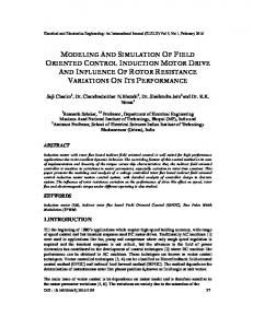
Figure 1: The Complete SIMULINK® Model of Three Phase Asynchronous Machine The sub-models of the various subsystems in the complete SIMULINK model are shown below (Figures 2 A-F).
(B)
(A) The Pacific Journal of Science and Technology http://www.akamaiuniversity.us/PJST.htm
–79– Volume 10. Number 2. November 2009 (Fall)
SAMPLE MACHINE DATA Rated Phase Voltage Winding Connection Rated Frequency Number of Poles Rated Speed Stator Resistance Rotor Referred Resistance Stator Reactance Rotor Referred Reactance Magnetizing Reactance Moment of Inertia Power Rating
(C)
220V Star 60Hz 4 1800rpm 0.435Ω 0.816Ω 0.754Ω 0.754Ω 26.13Ω 0.089Kg.m2 3-Hp
SIMULATION RESPONSE CURVES
(D)
Figure 3: Phase Voltage Vag against Time.
(E)
(F) Figure 2 (A-F): Subsystems Models of the Complete SIMULINK® Model.
The Pacific Journal of Science and Technology http://www.akamaiuniversity.us/PJST.htm
Figure 4: Externally Applied Mechanical Load Torque Tmech against Time.
–80– Volume 10. Number 2. November 2009 (Fall)
Figure 5: Phase Currents i as , ibs , and ics against
Figure 8: Electromechanical Torque Tem against Time
Time.
Consequently, with rated voltage applied, the starting current is large, in some cases in the order of 10 times the rated value. This is observed in Figure 5 and is a major limitation of the direct-on-line starting of the motor. It is, therefore, recommended that reduced voltage starting methods such as star/delta, auto transformer, and soft start methods be employed to reduce the excess starting current.
Figure 6: Per-Unit Speed
Figure 7: Motor Speed
ω r ωb
against Time.
ω r against Time.
OBSERVATIONS At stall, the input impedance of the asynchronous motor is essentially the stator resistance and leakage reactance in series with the rotor resistance and leakage reactance.
The Pacific Journal of Science and Technology http://www.akamaiuniversity.us/PJST.htm
It is observed in Figure 7 that the rotor accelerates from stall with zero mechanical load torque and, since friction and windage losses are not taken into account, the machine accelerates to synchronous speed. The application of 20N-m mechanical load torque at 3 seconds, as illustrated in Figure 4, results in a sharp drop in the motor speed of Figure 7 and an increase in the electromechanical torque in sympathy with the applied mechanical loading from [20 10 20] N-m in the time sequence [0.3-0.4] Seconds, [0.4-0.5] Second, [0.5-0.6] Seconds respectively as shown in Figure 8. Figure 6 is the per-unit speed used to compare the actual motor speed and the rated speed. The applied mechanical loading shown in Figure 4 is in negative sense since the machine is operating as a motor.
CONCLUSION Finally, this paper has demonstrated the ® in the Dynamic elegance of SIMULINK Modeling and Simulation of a 3-hp Asynchronous Motor Driving a Mechanical Load. With the model developed, the user has access to all internal variables for getting an insight into the motor operation. The simulated motor is symmetrical and windage and friction losses are assumed
–81– Volume 10. Number 2. November 2009 (Fall)
negligible for ease of analysis. Further researches are recommended in the area of closed loop speed control for adjustable voltage and speed drives.
Electric Machine Torque/Speed Control with Converters and Inverters) and Power Electronics.
SUGGESTED CITATION REFERENCES 1.
Richard, M.C. 1995. Electric Drives and Their Control. Oxford University Press: New York, NY.
2.
Okoro, O.I. 2005. ‘‘Dynamic Modeling and Simulation of Squirrel-Cage Asynchronous Machine with Non-Linear Effects’’. Journal of ASTM International. 2(6): 1-16.
3.
Ostovic, V. 1994. Computer-Aided Analysis of Electric Machines. Prentice Hall International: London, UK.
4.
Lee, R.J., Pillay, P., and Harley, R.G. 1984/1985. ‘‘D,Q Reference Frame for the Simulation of Induction Motors’’. Electric Power Systems Research. 8:15-16.
5.
Krause, P.C. and Thomas C.H. 1965. ‘‘Simulation of Symmetrical Induction Machinery’’. IEEE Trans. PAS-84. 11:1038-1053.
6.
Pillay, P. and Harley, R.G. 1983. ‘‘Comparison of Models for Predicting Disturbances Caused by Induction Motor Starting’’. SAIEE Symposium on Power Systems.
7.
Krause, P.C. and Thomas C.H. 1965. “Simulation of Symmetrical Induction Machinery”. IEEE Trans. PAS-84. 1038 -1053.
8.
Ong, C.M. 1997. Dynamic Simulation of Electric Machinery Using MATLAB and SIMULINK. Prentice Hall PTR: New Jersey.
9.
Ogbuka, C.U. 2008. ‘‘Aspects of Induction Motor Stator Voltage and Frequency Control’’. Unpublished M.Eng Thesis Department of Electrical Engineering, University of Nigeria, Nsukka.
Ogbuka, C.U. 2009. “Dynamic Modeling and Simulation of a 3-HP Asynchronous Motor Driving a Mechanical Load”. Pacific Journal of Science and Technology. 10(2): 77-82. Pacific Journal of Science and Technology
ABOUT THE AUTHOR Engr. Ogbuka, Cosmas Uchenna received his B.Eng. Degree (First Class Honors) and M.Eng Degree (Distinction) in 2004 and 2009, respectively in the Department of Electrical Engineering University of Nigeria, Nsukka where he presently works as a Lecturer/Research Student. His research interests are in Adjustable Speed Drives of Electrical Machines: (DC and AC
The Pacific Journal of Science and Technology http://www.akamaiuniversity.us/PJST.htm
–82– Volume 10. Number 2. November 2009 (Fall)