unicycle: L_ [Dr' Rt Dt ' Rr. +Dr -RI Rr. The relation (32) supposes that each of the two bicycle wheels satisfies ... Froumentin for his inestimable help during trials.
Aut!^mation and Robotics in Construction XVI © 1999 by UC3M
DYNAMIC MODELLING AND IDENTIFICATION OF A COMPACTOR
E. Guillo, M. Gautier Institut de Recherche en Cybernetique de Nantes, UMR CNRS 6597 B.P. 92101, Nantes Cedex 3, France E-mail: Eric . Guillo
ircyn.ec-nantesfr
Abstract: This paper deals with the design and identification of the dynamic model of a compactor, an articulated frame steering mobile engine for use in road construction. A classical approach based on an Ordinary Least Squares identification method is used. A survey of these techniques is given and applied to estimate dynamic parameters of the compactor, and especially the contribution of the contact strengths between rolls and soil. Keywords: Dynamic modelling , identification , Multisensory data fusion , mobile robots. constituted of rigid rolls, the conditions of contact are not similar to a classical wheel interaction with soil. Consequently, a dynamic model that explicitly takes into account bonding strengths is sum up in this paper (See [3] for details). An estimation of the parameters of this model based on an Ordinary Least Squares identification method [6] is given.
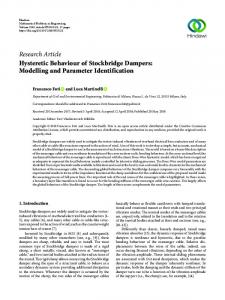
1. INTRODUCTION The compactor (see Fig. 1) is one of the most important equipment in the set of mobile engines which take part in the area of road construction. A typical use of compactor is in embankment, base and carriageway compaction. It can be seen that the vehicle must follow an efficient trajectory defined in position, velocity and acceleration according to engine degrees of freedom to guarantee the homogeneity and the expected density of considered compacted material. Those features should be improved taking into account a dynamic model compared with a simple path tracking using kinematic model.
2. DESCRIPTION OF THE COMPACTOR According to classical robot manipulator description [1], the compactor is considered as a mechanical c,-
There exists many kind of steering systems for earthmoving equipment. According to Dudzinski [2], systematic classification, the compactor (Fig. 1) has an articulated frame steering. Even if such structures are used for a long time (1913), their modelling will be essentially restricted to kinematic one which is based on velocity constraints as pure rolling and non slipping conditions [7]. As the rear and front axles of the compactor are
c,
I
Figure 2. Tree structure of the compactor. system E composed of a tree structure of Nrigid bodies C1 where Co is the base body, so that: N_ oCI N = 4 (1)
with the following body definitions ( see Fig. 2): • Co, C,: the front and rear chassis,
Figure 1. A typical compactor: Albaret VA 12 DV.
61
• C1, C4: the front and rear rolls. • C3: a virtual body (used to define a second frame R3 attached to C2).
where aA is the (3 x 3) rotation matrix which defines the orientation of the flame R, with respect to the frame Rai and a'Pi is the origin of the frame R1 expressed in the frame Rai.
The system E is provided with a frame R1 respectively attached to each of the (N+1) bodies Ci. Let Ri be defined as:
Remark 1. ui = I means that the i-joint is actuated and pi = 0 that it is not. ai specifies the type of the joint (6i = 0 if rotational, (y, = 1 if translational, a; = 2 if fixed).
Ri = (0i, x., y , z.) (2)
2.1 Compactor position
2.3 Generalized coordinates
Hypothesis 1. The compactor moves on the plane II which is perpendicular to the gravity.
According to the previous description of the compactor, the vehicle motion is completely described by the following vector of (n = 6) generalized coordinates:
Let Rg be a Galilean reference frame attached to the plane 11 so that:
T
Rg = (Og, xg'), g,zg) (3)
q(t) = 1-0 yo 00 01 02 04]
The robot posture can be described by the position and the orientation of the body Co with respect to the base frame Rg. It is given by the following three variables: • x0, yo: the coordinates of the reference point 00 in the frame Rg,
(5)
This description can be easily applied to other articulated frame steering engine like: double-jointed loader, loader with articulated pendulum joint and so on. On the other hand expressions of kinetic and potential energies using this description are well known for a while now.
• 00: the orientation of the frame R0 with respect to the frame Rg. 2.2 Parametrization of the compactor structure
3. DYNAMIC MODELLING Classical tree structure description using the modified Denavit-Hartenberg notations [5] applied to the system E defines the geometric parameters of the compactor (see Table 1) with respect to the position and orientation of the body CO. i
s
in
a
a
d
I
0
1
0
_n/2
0
2
0
1
0
0
-D2
3
2
0
2
0
-D3
4
0
1
3
_n/2
0
Let E be the mechanical system where position is given by the vector of parameters q and LE its Lagrangian. Let T (of same dimension as q) be the vector of the generalized forces applied to the system E. Then the vector q satisfies the following system of Lagrange equations: dt(aq(L,)) aq(L,) = 2 (6) When the Lagrange equations are calculated for the system E, they yield a dynamic equation which can be written in the form:
Table 1. Geometric parameters of the compactor In that case the homogeneous transform (4) of the frame Ri relative to Rai (where ai is the antecedent of i) is expressed as a function of the 4 following parameters: • ai: angle between za and zi , corresponding to a rotation about x • di: distance from za to z. along xa • 0i: angle between xa and xi, corresponding to a rotation about zi , • ri: distance from x to xi along z..
aiz
a a, A f, =i
=i
01x3 I
with a,A' = l a, a ill ark
J
M(q) • q + H(q, q) = T
(7)
where • M(q) is the (n x n) mass matrix of the system E • H(q, q) is a (n x 1) vector of centrifugal and Coriolis terms. The statement of forces acting on the system E is divided in two parts:
T = U+ Q (8) where U depends on the motor torques on joints 1, 2 and 4 as shown in table I and Q on the bonding strengths between the plan II and the rolls C1 and C4. The development of the vector r gives
(4)
62
T
Lz„
(9)
[o00u1 u2 u4,
Ar,
where ul is the motor torque on i-joint and Q=
IKi'
a0 n ' , c,
i = 1, 4 (10)
o where 3n ; - c points out the wrench of the resultant bonding strengths at point O. Its expression projected in frame Rai gives:
St = f F (n dl , a,
o; .3 n-->c; _
=f
FD'(Odl
with ' (11) S` = j Fn'(1)dl
Figure 3: Simplified roll-soil interaction model. angular part go of its circumference. Let Pi be a point of the surface Si.
l7 = f4(1 FD(^)dl
Remark 2 . (^, tl) are used to specify the relative coordinates of a point of the contact surface Si (see Fig. 3):
where
4 E Cogs = R'go l
= Rc.((P0 - rp) rl = I
(12)
nE
[-LC / 2,Lc,/2]
(15)
Hypothesis 2. The depression eZ in the ground is small compared to the radius R, of the rolls: eZ