Dynamic Multipath Allocation in Ad Hoc Networks Yosi Ben-Asher, Sharoni Feldman Computer Science Department, Haifa University, Israel.
[email protected],
[email protected] Moran Feldman Computer Science Department, Technion, Israel
[email protected]
Abstract Ad Hoc networks are characterized by fast dynamic changes in the topology of the network. A known technique to improve QoS is to use Multipath routing where packets (voice/video/…) from a source to a destination travel in two or more maximal disjoint paths. We observe that the need to find a set of maximal disjoint paths can be relaxed by finding a set of paths S wherein only bottlenecked links are bypassed. In the proposed model we assume that there is only one edge along a path in S is a bottleneck and show that by selecting random paths in S the probability that bottlenecked edges get bypassed is high. We implemented this idea in the MRA system which is a highly accurate visual ad hoc simulator currently supporting two routing protocols AODV and MRA. We have extended the MRA protocol to use multipath routing by maintaining a set of random routing trees from which random paths can be easily selected. Random paths are allocated/released by threshold rules monitoring the session quality. The experiments show that: 1) session QoS is significantly improved, 2) the fact that many sessions use multiple paths in parallel does not depredate overall performances, 3) the overhead in maintaining multipath in the MRA algorithm is negligible.1 Keywords: Ad-Hoc, wireless, streams, multi-path.
1
An early version of this work appeared in the International Conference on Advances in Mesh Networks, 2008.
1. Introduction The expectation from the emerging ad hoc technology, mainly in aerial vehicles, is to overcome the limitations of the existing point-to-point services. Such services include video streaming, stills pictures, data services and speech. The major limitation of these services is that they are limited to line of sight (LOS) between the peers. An ad hoc network creates a ubiquitous network that overcomes the no line of sight limitations by using fleeting agents as mediators between the communicating peers. Wireless transmission channels are very expensive, suffer from limited bandwidth and are vulnerable to disturbances. The multipath technology presented in this paper enables the peers to create a robust link between them by dynamically allocating multiple paths for a transmission that broadens on-demand the communication link between the parties, and creates in real time alternative paths to by-pass noisy wireless channels. The dynamic control of the quality of service (QoS) requires the peers to exchange control information. The target peer is required to monitor the pace of the inbound stream and look for missing packets. According to the expected level of the QoS, the target peer sends alarm messages back to the source peer. The overhead control traffic tends to zero in case of satisfactory level of QoS. Degradation of the QoS will trigger the target peer to send some worming messages to the source peer for a short time until the source peer initiates corrective actions. The small overhead of the QoS mechanism is very profitable in case where the completeness level of data transferred is critical as will presented in the rest of this paper. Ad hoc networks [1] are targeted to create a communication infrastructure in a dynamic environment characterized by high mobility of nodes with a limited transmission range. Routing problems caused by dynamic changes of links/edges in the network topology are handled by common ad hoc routing algorithms such as AODV [2]. Another problem that is not handled by these algorithms is congestion where some edges becomes a bottleneck slowing down the rate in which packets are received (QoS). Overcoming congested edges in ad hoc networks is harder than in static networks due to the rapid changes in the network's topology. Multipath routing is a basic technique used to bypass congested edges in networks and improve QoS. There are two ways to bypass a congested edge: abandon the current path and use an alternative path (hopefully without congestion) or use an additional path transferring
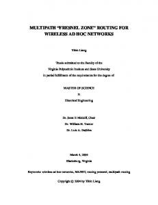
packets in parallel through both paths. Using parallel paths in ad hoc networks has been proposed by Lee and Gerla [3] with an algorithm (called SMR) maintaining two paths for each session. The goal of the SMR algorithm is to maximize the number of disjoint edges between the paths allocated to a given session. We observe that obtaining disjoint paths maybe too costly in ad hoc networks and propose instead to bypass a few most congested edges along the current path. Consider for example the following fragment of an ad-hoc network (Figure 1) where packets of a given session S are transferred. Each edge is labeled by a number representing the "potential capacity'' of this edge in relation to the given session. The potential capacity indicates the bandwidth available for S' packets on that edge. Ideally all edges could allocate the maximal potential capacity (12 in this example) however some edges are congested and can allocate less than 12. The minimal potential capacity along a given path determines the overall throughput of that path. In here, a congested edge with potential capacity 2 dominates all other "high" potential capacities (10, 7, and 12) of the selected path. Using an additional path 10-5-3-8-12 increase the potential capacity of the session to 5. Clearly selecting maximal disjoint paths will increase the potential capacity however this may be a waste of bandwidth since (as depicted in the example) we only have to bypass the most congested edge (assuming that there is only one such edge) to improve the overall potential Capacity. Ad hoc routing algorithms need to be fast and can not waste time determine which edges are congested and how to pass these edges. In here we propose to select an additional path in random from a set alternative paths. Random selection is simple and efficient yet (as we experimentally verify) has a high probability of bypassing the congested edge of a given path. Note that this type of solution differs from the classical works of using intermediate random intermediate destinations in permutation networks [4]. In this work we consider a simpler property of random radius graphs [5] describing snapshots of ad-hoc networks2 called the "bypass property".
2
Graphs obtained by connecting a set of nodes in the plane that are in transmission range where the coordinates of these nodes are random.
QoS is limited by the narrowest bandwidth on the Path 3 5 unloaded
8
12
10 7
2
Bottleneck Loadded
QoS is improved by using multipath to bypass the congested edge 3 5 unloaded
8
12
10 7 Loadded
2
Improved Capacity
Figure 1: Multipath Example
Let u,v be two nodes in a random radius graph and let Pu,v be the set of all shortest paths connecting u and v. For a given edge e on a path from u to v let x be the number of edges in a cut through e then the bypassing property holds if the number paths in Pu,v passing through e is 1/x. Thus the probability that a random path from Pu,v will bypass the "most congested" edge e is 1/x. This property of the set of all shortest paths is backed up by simulation results and some additional formal claims. Note that intuitively random selection of the additional path implies that:
If congestion changes from e to e' then the probability that the additional path
bypasses e' remains high.
Every time we select a path at random, the probability it bypasses a congested
edge remains high even if the underlying topology is utterly changed. The random selection is therefore suitable for ad-hoc networks where the topology and the set of congested edges can rapidly change.
Focusing on shortest paths is natural as ad hoc routing algorithms attempt to route packets through shortest paths. In addition we will show that extending the family of shortest paths destroys the bypass property and hence in some weak sense selecting from the set of shortest paths is essential.
A straightforward use of multipath abilities is to let every session use k > 1 random paths, however this may increase the overall congestion as each session attempt to increase its potential capacity. The solution is to allocate bypassing paths only to session whose QoS is dropped bellow a certain threshold and de-allocate bypassing paths when the QoS of session improves. For sending a stream of packets (video/voice/pictures) the QoS of a given session is measured by counting the current size of "holes" (missing packets) in a stream buffer at the destination. The full streaming protocol we have used combines three types of requests from the destination to the source:
Re-transmission of lost/delayed packets in "small holes''.
Rewind the transmission from a given point.
Allocating/de-allocating a new bypassing path.
Our experimental results prove that using multipath over the MRA algorithm can improve session quality by 40% without increasing the overall congestion (i.e., the use of mulipath transmissions at some sessions did not degrade the QoS of other sessions). In particular the experiments prove that the combination of multipath transmissions and streaming control is essential for maximizing the QoS. Tests where also made to determine the optimal threshold for allocating and de-allocating bypassing paths. Finally the experiments prove that the gain in using multipath transmission improves as the quality of the underlying network decreases.
The main contribution of this work is the use of a random selection of the shortest path out of a current group of “shortest paths” in order to bypass a congested edge, as opposed to the allocation of maximal disjoint path. The use of random paths significantly reduces the overhead involved with multipath transmissions compare to maintaining disjoint paths. A second contribution is the combination of allocating bypassing paths in a streaming protocol. We selected the MRA[6] protocol over other protocols to present our approach since the MRA maintains the shortest paths in a dynamic and seamless way. The rest of this paper is organized as follows. In section 2, we provide a background into the area of multipath routing in Ad-Hoc networks. In section 3, we present the Metrical Routing Multipath Algorithm (MRMA) that is an extension of the MRA protocol. This section gives a detailed view of the MRMA protocol and illuminates some theoretical aspects.
Section 4 presents various simulations including an analysis of the improvement in the QoS. Finally in section 5 we provide the conclusions and future research plans.
2. Related Work Multipath routing protocols have been deeply explored in wired networks [7][8]. This exploration broadened in Ad Hoc networks due to the special properties of these networks. The well known AODV[9] routing protocol is the origin for a group of multipath routing protocols. The AODV-BR[10] as a reactive routing protocol builds routs on demand via a query and reply procedure. The primary route and alternate paths are established during the route reply phase. The path detection takes advantage of the broadcast nature of the wireless network. Neighboring nodes use data received promiscuously from the broadcasting adjacent nodes. From these packets, the neighboring nodes can create alternative routes replacing parts of the primary root. The main idea in AOMDV [11] is that multiple link-disjoint paths are computed from the source top destination through a modified route discovery process. Each node in the network maintains a list of alternative “next hope”. If during routing, one of the links between two nodes breaks, then the immediate upstream node switches to the next node in its list of next hopes. This caching mechanism does not refresh the alternate link paths and the paths become outdated. An attempt to solve the aging problem is presented by the MP-AOMDV routing algorithm [12]. It attempts to solve the problem of unrefreshed paths by periodically revalidating each of the alternate paths, while introducing a minimum of control overhead. The source node does not wait for its current path to break in order to switch to an alternative path. Instead, it constantly monitors of each of its alternatives paths and always selects the best path among them. AODVM[13] protocol has the ability to find node-disjoint paths. The AODVM protocol uses a subset of reliable (Rnodes) mainly used for creating a reliable routing framework within the ad hoc network. The R-nodes are placed sparser regions of the network targeted to increase the reliability of the paths between two arbitrary nodes. The A2OMDV[14] addresses the limitations of the AOMDV. The source node maintains a multiple disjoint paths to its destination and keeps monitoring the quality of the routes. If the performance of the selected route drops bellow a certain threshold, the source node picks another route from the bank of potential routes based on the round trip time.
The ability to create multiple paths lies in DSR[15]. The DSR uses source routing and can gather route information per route discovery. An interesting and innovative approach is presented in [16]. The DSR uses a directional antenna to minimize the interference and the contention between transmissions. This method enables the route search process to create more potential routes. Ref[11] points to the fact that aggressive use of route caching and the absence of an efficient mechanism to purge stale routs leads to reply storms and performance degradation. The ROAM [17] routing algorithm is an “on demand” routing algorithm that searches for a new path only when there is a need for it. It provides a multiple loop-free paths based solely on distances to destinations, without the need to complete path information, sequenced numbers refreshed periodically, or time synchronization. Given its performance, ROAM is suitable to wired networks and wireless networks with static nodes or nodes with limited mobility. An on-demand routing protocol that builds multiple disjoint routs with maximal disjoint paths using request/reply cycles is the SMR [3]. When no information is known about the requested path, it floods the entire network with a Route Request message. The scheme uses two routs for each session; the shortest delay route and the one that is maximally disjoint with the shortest delay route. Another on demand routing protocol, TORA [18] present a multipath routing loopfree algorithm tailored for operation in a highly dynamic environment. It uses time stamps and internodal data to avoid looping. The protocol is designed to minimize the reaction to topological changes by decoupling the generation of potentially farreaching control messages propagation from the rate of topological changes, as these messages are typically localized to a very small set of nodes near the change. The common to all protocols described above is the effort to allocate a full path, mostly a disjoint one. The MRMA protocol presented here takes a different direction. It is targeted to allocate efficiently additional paths to a support a session. The exclusiveness of the MRMA is its ability to select on demand new one or more paths that bypasses the congested edges.
3. The Metrical Routing Multipath Algorithm (MRMA) Algorithm The MRA[6] algorithm is the foundation for the MRMA multipath algorithm. In this section we will describe the extension to the MRA algorithm upgrading it into a multilevel algorithm supporting retransmissions in the first level and multipath in the second level.
3.1 MRA Overview The MRA algorithm organizes the nodes in the field in rooted trees with shortcuts (STSC). Figure 2 present a STSC (the root node gets always the address , the root children gets the address etc.). The arrows between nodes , and presents shortcuts. A session is not compelled to use the structure induced by the tree structure. It uses shortcuts to minimize the path length or avoid potential bottlenecks. Only nodes that belong to one tree can create sessions among themselves. To ensure the maximal connectivity, all nodes will try to organize themselves in a single tree. In the rest of this document we use the terms STSC and “tree” as replaceable terms.
Figure 2: Sample tree
Every node in the field has a unique node-id and virtual coordinates that may change depending on the changes in the tree structure triggered by nodes movement. Every tree is identified by a “tree name” which is the id of the root node. Thus, different trees are identified by different id's. Nodes send periodically beacons (hello messages). Every node that receives a beacon checks whether the node that sent the beacon belongs to a different tree. If the nodes belong to different trees, they will initiate a fusion process that will fuse the separate trees into a single bigger tree as presented in Figure 3. The fusion of small STSCs into a single larger STSC with
more nodes expands the connectivity and enables the nodes to create more shortcuts and as a result shorter paths. 1
1 3 2
3 2
Figure 3: fusion process – small trees fuse to a large tree
A session path is induced from the tree structure and possible shortcuts on the tress. Simple rules define the fuse process of nodes into trees. The basic rules are: 1. A smaller tree will fuse into the bigger tree. 2. In case that two trees have the same size, the trees use a tie breaking rule that enables the fuse of both trees into one big tree. (Initially, single nodes are trees with a single node). Note that every root node has a good approximation on its tree size. This information is diffused from the leaves to the root using the beacon message.
3.2 Random creation of STSCs in the MRMA algorithm The MRMA algorithm utilizes the trees creation process of the MRA algorithm with minor changes. While the MRA algorithm uses a single tree to create a session path between any two nodes. The MRMA algorithm is able to create a set of independent trees on the same nodes collection. The creation rules select for example the node with the highest node-id to be the root in the primary tree and the node with the lowest node-id to be the root in the first secondary tree. Note that the node-ids are unique. Similar rules apply to the creation of the other secondary trees. The control information maintained by the primary tree is used also by the secondary trees and as a result there is a significant time saving in the time required to allocate a secondary path compared to the time required to allocate a primary path. Figure 4 presents a collection of 12 nodes in the same position arranged in 2 different STSCs. The creation of different trees is applicable by using random creation rules. Potential shortcuts are presented by bi-directional arrows. In the example presented in Figure 4A, the path from S to T is SBCT and in Figure 4-B the path from S to T is SDET. Note that in these examples, the session paths do not follow the trees structure as shortcuts are used. The foundation of the multi-path algorithm is its ability to establish dynamically and instantly distinctive routes between the session end points (S and T). Our solution minimizes the overhead needed to create and
maintain multiple session paths and is based on replication of the STSCs mechanism of the MRA.
A
B
0.3.1.1 0.3.2.1
0.3.1
T
0.3.2.2
0.3.2 C
0.3
E
0.2.1.1.1 0.3.2.1
T
0.2.1.1
0.3.2 C
0.3.1
D
D
0.2
0.3.2.3
B
0 0.1
0.3.2.2
S
0.1.1
0.1.1.1
E
0.2.1
B
0.3
0.3.3 0.1
S
0.2
0
Figure 4: Trees structure
The first STSC is the "primary" STSC and the other STSCs are "secondary" STSCs. Targeted to keep the management of the secondary STSCs light, we used the messages and control structures of the primary STSC for the control of the secondary STSCs. The autonomous activities used by every secondary STSC to maintain itself were kept minimal. The number of secondary STSCs that can be created is not limited. In our test environment, we limited this number to 4.
3.3 Sessions stream protocol A session between two nodes is initiated by the originating node which searches and allocates a session path. We will define this path as the “primary” path. The MRMA allocates a bi-directional session path induced from the primary tree structure. The direction from S→T is used to transfer data packets while the direction T→S on the primary path is used to transfer the protocol control actions described later. As soon as the originating node gets the indication that the session creation process succeeded, it starts to transmit data packets towards the target node. Every data packet is numbered with a consecutive number. The target node monitors constantly the inbound stream of packets. An audit process in the target node (T) evaluates continuously the inbound packets and stores them according to the packet sequence number in a test buffer (TB) dedicated for this purpose. Based of the analysis on the density and the number of missing packets done by the audit process and depending
on the application type (voice, video, FTP etc) transferred from S to T during the session initiation process together with additional session control parameters the target node can take the following actions: 1. Proceed with the transfer process. This decision will not trigger any corrective actions as no packets were lost or there is no need to activate corrective actions. 2. Request the originating node to retransmit specific packets. In this case, every retransmission request will be for a single packet(s) (for example retransmit packet 4 and 11). 3. Request a range retransmission. Whenever a group of packets are missing, the destination node requests the source node to retransmit a range of packets (for example retransmit packets 3 to 7). The decision whether to use specific retransmissions or range retransmissions is based on a utility function that minimizes the number of messages needed to complete the missing packets. 4. Activate a secondary session path. This action will trigger the allocation process of a secondary path. As soon as the path is established, the traffic will be distributed between the primary and secondary path. This process is an iterative process as every one of the existing paths can be supported by another secondary path that will carry “half” of the traffic of the original path. Figure 5-A presents the initial phase of a session and the double window test buffer. Node S (Source node) created a bidirectional primary session path towards node T (Target node). The dotted slots on the TB present lost packets. Figure 5-B presents the decision of the audit process in node T to open a secondary path (S1) that will support the packets transfer by sharing the load between the two active paths. The TB in this case hosts records from P and S1. The dotted slots present empty slots of packets sent on path “P” but got lost on their way. Figure 5-C presents the case where the target node initiated the activation of another secondary path (S2) that will support S1 path. In a similar way, Figure 5-D presents the case where a new secondary path (S4) was created to support the primary (P) path. 5. Terminate a secondary session path. This action is activated when it is possible to merge back two paths into a single path. The path merge process runs in reversed order to the activation process of new paths.
During the allocation process of a new path, the participating nodes reserve resources for the path, when the main resource is bandwidth. Every node on the path links the
incoming and outgoing sides of the path. As soon as the path is established, the source starts to send packets as a stream without waiting for an explicit acknowledge (Ack) for every packet. A packet can be lost due to nodes movement as moving nodes on the path may get out of transmission range or a node queue may become temporarily overflowed. Every packet sent from the source node (S) gets a sequential number. This number is used as an index to a TB in the target node. A packet received in the target node is stored according to its number in the appropriate slot inside the TB. P
A
B
P
P
S
P
P
P
T
P S S 1
P
S1
P
P
S1
P
S1
P
T
S1
S1
S1 P
C
S2 S1
S1
P S2 S1
T
P P P P P S S S2 S 2 1 S2 S1 S1 S3 S3 S1 S3
P S2 S1 S3
T
S1,S3
P
S1
P
S3
P P P S S S2 S2 1 S1
D
Figure 5: Session path allocation (P=Primary path, S=Secondary path)
The TB in the target node uses a double window mechanism. While storing the received packets in one (active) window, it analyzes the content on the other (inactive) window and if needed initiates corrective actions. The source node transmits packets in a constant rate of n windows per second (n depends on the application type, size of packet and bandwidth) and this is the rate that the target node expects to receive the packets. The first level of corrective actions will resume the transmission of missing packets that will fill the empty slots in the inactive window. A trigger to switch the windows will be an event where the last empty slot of the active buffer gets a packet or the last packet index is higher than the indexes in the active window. In this case, the content of the inactive window will be stored on disk, and the buffers will switch. A packet will be declared as an unrecoverable packet when the non active window must change its state to an active window.
In case that the Quality of Service interpreted the number of missing packets and their density of a path crosses a predefined threshold, the target (T) node will initiate the allocation of an additional path. In case that the QoS improves and crosses an appropriate threshold a merge process will merge secondary paths. We limited the number of paths that can be allocated for a single session to 4. A secondary path will merge back with its original path when the QoS betters and crosses a threshold. Events Impact on Delays Table 1 depicts the four events related to the management of packet loss and creation of a secondary path. From the analysis of the events we learn that the saving of time while using the multipath, results from the decrease of traffic on the overloaded path and its diversion to secondary paths implies less packets loss. This traffic decrease on the primary path increases indirectly the QoS of other sessions that use nodes on the primary path. The allocation of a secondary path in not engaged with delays as this process is performed in parallel to the existing flow of messages. Only after the establishment of the secondary path, 50% of the traffic will be diverted to the secondary path. Table 1: Events Impact on Delays
Event Allocating secondary path Packet transmission on secondary path Packet retransmission Request for retransmission
Recovery Method Retransmissions Multipath Not Applicable Reduces the total number of retransmissions on primary path and prevents delays Delays transmission No delay
No delay Reduced load on all paths. reduced need for retransmissions Not Applicable Not Applicable
Similarly, a request for retransmission of a lost packet does not "cost" time. However, the resending of a lost packet results in a delay that will be aggregated to the total session time.
4. Justification of the bypassing property Let Ps,t be the set of all shortest paths between two nodes s and t and let u be a congested node in a pre-designated path in Ps,t. For a given node u in Ps,t the bypassing property for the triplet indicates that if we select a random path p in Ps,t then the probability that p bypasses the congested node u is greater equal ½
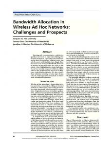
(assuming that there are at least two nodes in the level of u in the induced graph of Ps,t). An empirical justification for this property can be easily obtained. Figure 6 presents the results of a set of simulations performed on a theater hosting from 50 to 300 nodes. The “good triplet” presents the number of triplets satisfying the bypassing property and “bad triplets” presents the number of triplets that do not satisfy this property. Note that the “good triplets” curve grows approximately to the square number of nodes, while the number of “bad triplets” grows linearly. Thus, empirically this property holds. 1200000 1000000 800000
sessions
“bad triplets”
600000 400000 200000
“good triplets”
0 50 60 70 80 90 100 110 120 130 140 150 160 170 180 190 200 210 220 230 240 250 260 270 280 290 300
Number of nodes good triplet
bad trpilet
Figure 6: Number of good triplets Vs. bad triplets under traffic load
A more formal basis for the claim that in ad hoc networks most triplets satisfy the bypassing property can be obtained by considering level graphs. An acyclic graph G is a level graph (LG) if we can associate a level l with each node in G such that each node in level l is connected only to nodes in levels l+1, l-1 (except end point nodes l=0 & l=maxlevel connected l=1/l=maxlevel-1). For every LG we consider two special nodes s,t where s is connected to all nodes of the first level and t to all nodes of the last level. It follows that Ps,t is always a LG as it contains only shortest paths between s and t. Figure 7 depicts such a case where a LG is formed in a given snapshot of an ad hoc network. It is thus sufficient to show that the bypassing property holds for LGs. We first prove this for "fixed degree" LGs (where the indegrees and out-degrees are the same at every level) and extend it for LGs where the in-degrees/out-degrees are selected at random from a bound range.
Figure 7: a leveld graph in an ad hoc network
Claim 1: Let G be a LG such that the in-degrees/out-degrees at each level are the same. Let s and t be the two end nodes then the number of paths from s to t is equally partitioned between the nodes of every level. Proof: The number of paths from s to every node u is the multiplications of all the indegrees at each level. Since the in-degrees at each level are the same then the number of paths from s to each node in a given level is the same. A similar argument yields that the number of paths from t to all the nodes of a given level is the same (using the fact that the out-degrees at each level are the same). Thus for every node in the same level, the number of paths from s to t passing through that node is the same. ▌ Corollary 1: Let G be a LG where nodes at each level have the same in-degree/outdegree respectively then if the number of nodes at each level (m) is greater equal 2 then G satisfies the bypassing property. Proof: Let u be a node in level k of a given LG then (base on claim 1) the probability that a random path from s to t will not pass trough u is 1-1/m. Thus for m ≥ 2 the bypassing property holds. ▌ A similar claim can be obtained for edges in LGs with the same in-degree/out-degree at each level. Corollary 2: Let G be a LG where nodes at each level have the same in-degree/outdegree respectively then the number of paths through every incoming/out-going edge of the same level is the same. Proof: Every in-coming/out-going edge can be split to two edges by inserting a dummy node in the "middle" of that edge. The result is a new LG G' with one to one matching
between the set of paths from s to t in the two graphs. Applying claim 1 to the middle nodes in G' yields the claim for G's edges. ▌ It can be shown that even a small deviation from LGs with fixed in/out-degrees will lead to a violation of the bypassing property. Figure 8 shows an example of a LG where the in-degrees and the out-degrees can be 2-3 yet there is one congested node and edge where most of the paths pass. The LG is composed of a left/right columns with two nodes at every level and a middle column with three nodes at every level. Almost all the nodes at the right and left column have in/out-degree=2 while all nodes at the middle column have in/out-degree=3. Thus most of the paths order of 3k pass through the middle column compare to order of 2n in the left and the right column. The middle column contains one special edge at the middle where all paths from the bottom to the top must pass through. The end-points of this congested edge have been connected to the left/right column such that it is not possible to create a path that leaves the middle column and then return back to it. Consequently there are 32k paths going through the congested edge, 22k at the right/left column, 2k×3k paths from the left column to the upper half of the middle column and 2k×3k paths from the right column to the lower half of the middle column. Thus the vast majority of the paths (ratio of (3/2)k ) goes through the congested edge. ………….. K-LEVELS …………...
MOST OF THE PATHS
………….. K-LEVELS …………...
Figure 8: a LG violating the bypassing property.
In spite of this example the bypassing property holds for random LGs. Consider the case of a LG with two nodes at each level. A graph G is a random binary level graph (RBLG) if G is a LG with two nodes at every level such that the connections between each level are uniformly selected from the following set of five possible "connectors":
There are two special nodes s/t connected to the first and the last level respectively. The path relation at level i is the ratio sGi ,1 t Gi ,1 sGi , 2 t Gi , 2 where s(Gi,j)/ t(Gi,j) is the number of paths between s/t and node j (j=1,2) of level i. Theorem 1: For a given RBLG G with n levels the probability that the path-relation of more than 10% of the levels is larger than 121 is exponentially small in n. Proof: The value of s(Gi,j) is affected by the type of the next connector as follows (similarly for the value of t(Gi,j) ) :
Connector
Parallels
s(Gi,1)/s(Gi,2) sGi1,1 sGi1, 2
Cross
Butterfly
1 1 sGi1,1 sGi1, 2
Normal N
Mirrored N
1 sGi1,1 sGi1, 2
sGi1,1 sGi1, 2 1 sGi1,1 sGi1, 2
Let a normal-N/mirror-N sequence be a consecutive sequence of normal-N/mirror-N or Parallel connectors. Let a Segment-Normal-N (Segment-Mirror-N respectively) of level i be the maximal sequence of normal-N and mirror-n sequences separated by cross connectors containing level i. Intuitively a segment is a sequence of levels terminated by a butterfly or normal-N/mirror-N exchange without a cross connector in between. Note that (Gi,1)/ s(Gi,2) in a segment is monotonely increasing for normal-N segments and monotonely decreasing for mirror-N segments. It is important to note that every level in a RBLG is a member of a segment of each type. Some segments have length zero, for example segments of levels connected by "Butterfly" connector in both ends. The following claim is immediately follows from the definition of a segment and the effect that each type of connector on s(Gi,j)/ t(Gi,j): *.10. Claim: Let G be a RBLG and let i be a level of G. Let S be a segment of level i of length n in G and let h denote the height of level i in S. The following inequalities holds:
If S was chosen as the Segment-Normal-N then:
sGi ,1 t Gi ,1 sGi , 2 t Gi , 2 h 1 n h 1
If S was chosen as the Segment-Mirror-N then:
sGi ,1 t Gi ,1 sGi , 2 t Gi , 2 h 1 n h 1 1
1
Returning to the main proof. We will prove that with high probability no more than 10% of the segments are long segments (segments of length 20 or more), indicating that most segments are short and by *.10 does not give room for extreme sGi ,1 t Gi ,1 sGi , 2 t Gi , 2 values. It can be shown that if a segment S of level i contains level j, then S is also a segment of level j. This means that the graph can be split into a series of covering independent sections, each section acting as a segment to all the levels it includes. Since each level is a member of two segments (Segment-Normal-N and Segment-Mirror-N) there are two ways to perform the split, each matching one of the two segments to each level. A segment is terminated either by a butterfly connector or by one of the N connector (Normal or Mirror) whose type does not match the segment at this place. This means that each segment has a probability of 2/5 to be terminated by each connector, when the connectors are chosen in random. From this point on we will make all the calculations for one of the two splits into segments discussed above. The calculations for the other split are identical. We divide the graph into sectors. The i-th sector contains all the levels between 10i and 10i+10 (inclusive) and the 10 connectors between them. We will calculate the probability that there is a complete segment inside a sector, in other words, we want to calculate the probability that two segments terminate within a sector. There are 10 connectors in a segment, each having a probability of 2/5 to terminate a segment. Let X i be a random variable of the number of segments terminating within the i-th sector, then Xi has a binomial distribution B(10, 2/5). We want to find the probability that Xi is 2 or more. 0 10 1 9 10 2 3 10 2 3 PrX 2 1 PrX 2 1 PrX 0 PrX 1 1 0 5 5 1 5 5
1 0.610 4 0.69 0.954 This means that the probability that a sector does not contain a full segment is 0.046. Let Y be a random variable of the number of sectors not containing a full segment. Since the sectors are independent of each other, the distribution of Y in a graph containing n sectors is B(n, 0.046). The expected value of Y is 0.046n. We will show that the probability that Y is larger than 0.092n decreases exponentially. Using the Chernoff bound we get:
PrY 0.092n PrY 1 10.046n e0.046n1 / 4 e0.0115n 2
If we consider any segment longer than 20 as a long segment, then each long segment includes at least one section that does not contain a full segment. This means that with high probability the number of long segments does not exceed 0.092n. We know that with high probability the number of sectors containing full segments is at-least 0.908n, implying that the total number of segments is with high probability at-least 0.908n. We conclude that with high probability the fraction of the segments that are long is no more than: 0.092n/0.908n = 0.101 (≈10%). This result implies that with high probability 90% percent of the segments have a length
of
no
more
than
20.
Following
*.10
we
get
that
the
ratio
sGi ,1 t Gi ,1 sGi , 2 t Gi , 2 in 90% of the segments does not exceed 121 and is no
less than 1/121. Although this result might seem weak for practical purposes, it has a theoretical importance for showing that the probability that the ratio will exceed a specific constant for more than 10% of the segments decrease exponentially with n. ▌ For practical purposes we can look at the expected segment length. A segment can be terminated by two of the five connectors at each level. This means that the length of the segment has a geometrical distribution, with 2/5 as the parameter. The expected value of such a distribution is 5/2, implying that the expected length of the segments is 2.5 and the expected maximal sGi ,1 t Gi ,1 sGi , 2 t Gi , 2 ratio in a segment is (2.5 / 2 + 1)2 = 5.0625.
Though this proof is to the special case of RBLGs it can be extended to any random LG with a constant number of nodes at every level. The formal justification for the use of the bypassing property is thus due to the assumption that at any given time Ps,t in a given ad hoc network is a random LG with small constant number of nodes at each level. This is a reasonable assumption as in ad hoc networks cases usually the number of connections for most of the nodes is bounded in a small range. Note that the negation of this assumption implies dense pockets where large number of nodes is concentrated in a small area.
5. Simulations 5.1. Simulations Environnent The simulations were performed on an existing ad-hoc IFAS simulator[19] expanded to support not only voice sessions but also large data (LD) sessions. This includes the addition of the MRMA algorithm for multi-path transfers and the session stream protocol. Special care was taken during the design and implementation of the simulator on the following aspects: (a) enhanced visualization tools that give a full online view of the testing field, nodes movements, voice channels, data channels, specific node status including queues status etc. Figure 9 presents the main view of the simulator (b) Tracing the forming of trees in MRMA protocol. (c) Tracing the sessions in real time (d) Configuration via online screens (e) Support of logging, debugging and analysis tools.
The Communication Model The communication system is responsible for transferring applicative data among nodes. The communication model is composed of 2 tiers: the Medium Access Control (MAC) layer, which is based on a 802.11[20] standard; the MRMA which runs on top the MAC layer and is responsible for routing messages between nodes.
Radio Propagation Model (RF) The RF model is used to quantify radio propagation between any two nodes in the theater. We assume that the transmitters use isotropic antennae that radiate uniformly in all directions. This type of antenna is often used as a reference for antenna gain in wireless systems. It uses the Effective Radiation Power (ERP) formulas, given below. The loss factor between a transmitting and a receiving node, denoted by loss and measured in units of dB, assuming RF propagation using a free-space transmission between two points at a distance d, is given by: loss 92.5 20 log(d f )
where d is in units of km and the transmission frequency, f, is measured in GHz. Similarly, the loss factor for RF propagation of antennae that are near the ground is given by:
(1)
loss 40 log( d ) 20 log( Ht Hr)
where d is distance between antenna in meters and Ht and Hr is the altitudes of the transmitter and the receiver in meters, respectively, above the ground. Similarly to the management of the RF model, it is possible to manage the links bandwidth and packet transmission rate. The simulator runs in parallel voice and LD sessions. This combination allows us to create a high load on the network resources. A voice session is a full duplex connection between nodes while a LD session is a unidirectional session when data packets are transmitted from the source to the destination node. Control messages are transmitted from the source to the destination node and vice versa. A message can be lost for example because of an overflow of the queue in one of the chain of nodes used by the session, a disappearance of a node or an intermediate node that gets out of range due to normal node movement. Note that in case that the QoS drops bellow a predefined value the session will be dropped. Simulation Main Parameters The following values were used in the simulations. Table 2: Main simulation parameters Attributes Theatre Size No. Of nodes in simulation Node Movement Transmission Radius Session setup retries Path Bandwidth Session Length Queues Size Sessions Load Transferred data
Selected Values 15Km x 15Km 230 nodes 100Km/h – 170Km/h (27.7m/s – 47.2m/s) 1KM, 3.75 Km. 3 retries. The session will be dropped after the 3rd false retry. 20KB / second Voice Sessions: 5 seconds Data Sessions: until end of data Range of 10 -70 messages The simulator tried to establish the maximal number of possible sessions (115 sessions) Data sizes: 50KB, 190KB, 236KB, 381KB and 2.0MB.
(2)
Figure 9: Simulator Sessions Presentation Screenshot
We defined two types of networks profiles – dynamic and static. The first profile is characterized by often changes in the network structure and the second one is much more stable. These profiles are achieved by changing the transmission range of the nodes and the nodes movement speed. A shorter transmission range implies a more disturbances due connection drops. Another factor that rises in case we use a shorter transmission range is the need to include more nodes in every session. Naturally, a session that is composed of fewer intermediate nodes is less exposed to communication losses than a session that uses fewer nodes. The traffic in the network is constructed of two types of LD sessions: "short" and "long" unidirectional LD sessions with the duration 10 seconds and 3-5 minutes respectively. The session initiation process is identical in both cases. The establishment of a session and the allocation of a session path require a toll resulting in a short pick of control messages on the tree. The stable phase of a session is characterized in a constant uniform flow of messages over a fixed path. In addition to the LD sessions there is a third type of voice sessions.
5.2. Experimental results Every LD session gets a final score that presents the success of this session. A LD session that succeeds to transfer 100% of the packets gets the grade 1. A session that succeeds pass 95% of its packets gets the grade 0.95. An example of a LD that got the grade 1 is presented in the left side of Figure 10, and the same picture that got the grade 0.73 is presented in the right side. Recall that packets can be declared as unrecoverable due to the double window mechanism.
Figure 10: Anemone flower with grade 1 and 0.73
5.3. Methods Comparison and analysis We divided the experiments into two families of tests: The first group of tests is aimed to evaluate the contribution of every recovery method under various conditions. The second group of tests is aimed to find the complementary conditions that maximize the efficiency of the recovery methods. All simulations were performed in an identical theater and under equivalent load of mixed LD and voice sessions. Every LD session was graded according to the number of packets that passed successfully from the source node to the destination node. In case of missing packets, the target node will request the source node to retransmit the missing packets or initiate the allocation of a new session path that will share the load with the faulty path. In the following simulations, a new path is allocated when the destination node evaluates that at least 15% of the packets are lost. Paths will rejoin when the destination node evaluates that the number of lost packets on every path that is a candidate to the join is smaller than 3%. There is no dependency between the retransmission part of the session stream protocol and its multipath part hence it is possible to disable each of them or both of them.
5.3.1 First Group Tests - Recovery Methods Contribution 5.3.1.1 Network and Traffic classification We have classified the networks into two classes – a dynamic network that is characterized by often changes in the connectivity of the nodes and a static network that is characterized by a low pace of changes. The main factor influencing the behavior of the network is the transmission range. A short transmission range leads towards a dynamic network while a long transmission range leads towards a static network. The source node sends a constant flow of packets. The decision whether to open or close a secondary path is based on analyzing the reception quality on window level. Too many lost packets or a high density of lost packets will lower the QoS and as a result will trigger the appropriate recovery actions. For example, a phone call session can proceed as long as the number of lost packets does not exceed 10% (distributed uniformly) of the total number of packets. The number of lost messages was used in our simulations as the leading QoS evaluation parameter. We evaluated the QoS of each recovery method in dynamic and static networks under two different traffic categories – "long" where long data transfer sessions are used and "short" where short sessions are used. We graded the results in the grades 1-5 according the percentage of successful records transferred as presented in Table 3. Table 3: Grades Translation Percentage of transfer
0%-80%
81%-85%
86%-90%
91%-95%
95%-100%
Grade
1
2
3
4
5
The tests were performed without time limit. Table 4 depicts the summary results of our observations. We analyze the observations according to the recovery method. 1. No recovery method: The transfer of the long data files was graded with the grade 1 as the QoS dropped to the minimal value due to packet loss. Better results were achieved with short sessions since part of the sessions were completed before there were any communication breaks. 2.
Multipath: There is a significant improvement over the previous case. The
improvement in the static network is higher than in the dynamic network. The contribution of Multipath recovery method to the QoS is much more significant in the case of "long" sessions. The reason for the gap between the "long" and "short" is
derived from the recovery procedure. After the first packet loss, a process of allocating a secondary path is launched. During this process, the primary path is exposed to further packets loss. Naturally, the ratio between loss and received packets in the "short" sessions is significantly higher than the ratio in the "long" case. Table 4 :Sessions Quality Distribution Recovery Method
Traffic Category
Dynamic Network
Static Network
Long short Long Short Long Short Long Short
1 3 2.5 1 2 3 3.5 4
1 4 4 3 3 4 5 5
No Recovery method Multipath Retransmissions Retransmissions + Multipath
3. Retransmissions: The gap between the "long" and "short" sessions shrinks compared to the multipath recovery method. The retransmission recovery method has an advantage over the multipath method in case of sporadic packet loss as the recovery price is cheap and if it succeeds, it assures that the session will be fully successful. The multipath method has an advantage over the retransmission method in case that a batch of packets is lost or groups of isolated packets are lost. A full explanation is given in section 3.3. 4. Retransmissions + Multipath: this combination results with a level 5 performance in static networks and good results in the dynamic case. The combination of these methods gives on the one hand an immediate answer to the case that sporadic messages are lost and on the other hand a "long term" solution to the case where extra secondary paths are needed.
5.3.1.2 Recovery Time Comparison An important factor is the ability to transfer a data file from the source node to the destination node in an expected period of time. The following test presents the difference in the capabilities of the recovery methods to transfer the files on time. The actual time for a file transfer is constructed from the time needed to transfer the data and the time needed to establish the path between the source and the destination nodes. The time to establish the path is divided into two parts: the address resolution interval needed to access the hash nodes in order to get the destination node current address in
the tree and the path allocation process. The second time interval is used to allocate a path and resources. We selected to run the test under an average loss ratio of 10%. A higher loss ratio may trigger the system to declare the path as a faulty path and try to allocate a new path for the session. Table 5: LD Summary (in seconds)
Performed Function Base transfer time (without errors) Transfer time with 10% packet loss using retransmissions Transfer time with 10% packet loss using Multistream and retransmissions
Theater Type Static Dynamic 1550 1702 1600
1680 1915 1860
Table 5 presents the time in seconds needed to transfer 100 short test files in static and dynamic theatre. In the static case, the additional recovery time needed to transfer the files when only retransmissions are used grows by 152 seconds over the base time, which adds extra 10% time. The time needed to transfer the file using both Multistream and retransmissions grows by 50 seconds over the base time, which represent an increase of 3% in transmission time. In the static case, the results present an actual reduction of 67% in the time used by the recovery process. In the dynamic case, the additional recovery time needed to transfer the files when only retransmissions are used grows by 235 seconds over the base time, which adds extra 14% time. The time needed to transfer the file using both Multistream and retransmissions grows by 180 seconds over the base time, which represent an increase of 11% in transmission time. In the dynamic case, the results present an actual reduction of 23% in the time used by the recovery process. The results show that the efficiency of the Multistream recovery method moderates in the dynamic case compared to the static case. This decrease results from the increase in the number of broken paths due to the dynamic nature of the network. Note that in our architecture it is possible to run the Multistream recovery mechanism as a standalone recovery method. However, in this case it is not possible to recover lost messages.
5.3.1.3 Slicing the results Table 6 presents the results of a different set of tests where we classify every session to its success group according to the number of messages that the session succeeded to transfer. For example, tn the case where no recovery method is used, 265 sessions
succeeded (64%) to transfer 100% of their packets while 150 sessions failed to transfer 100% of the sessions. The contribution of the recovery methods to the QoS are observed also in the distribution of the sessions that failed to transfer 100% of their packets. In the case when both methods are used, the tendency of the grades is to concentrate in the upper grades groups while in the case when no recovery method is used the results are spread over all grades groups. Analyzing the cases when only a single recovery method is used presents a slight superiority to the retransmissions method over the multipath method. Table 6: LD Grade Distribution
Recovery Method
Session Grades Group (Percentage) 40-49 50-59 60-69 70-79 80-89 90-99 1 0 0
Retransmissions+Multipath Retransmissions Multipath No Recovery
0 0 0 2
0 0 1 1
0 0 2 6
2 7 4 10
7 19 12 28
55 123 133 103
383 283 275 265
Total No. of Sessions 447 432 427 415
The conclusions from this test are: (1) A constant improvement of LD quality as we move from no-recovery Multipath Retransmissions retransmissions + multipath. The improvement is reflected by a constant growth in right column “Total No. of Sessions” and a shift to the right in the percentage columns. Note that the best results are achieved when both methods were used. (2) The multipath recovery method does not stall the ad hoc network by allocating extra paths and utilizing extra resources. 5.3.2 Second Group Tests - complementary conditions 5.3.2.1 Recovery Methods Contribution The evaluation of the retransmissions and the multipath recovery methods to the QoS were performed in an equable theater. We used the queue size of the nodes as an instrument to control the packet lost rate. We run identical tests on the network with different queue sizes. In the following tests, a session is counted as a successful session when it succeeds to transfer 100% of its packets. Figure 11 depicts the number of successful sessions as a function of the queue size. We tested the performance under various queue sizes with the capacity of 10 to 70 messages (full parameters list appears in Table 2). Both multipath and retransmissions recovery methods were used in these tests. The number of successful sessions when
the queue size is below 20 messages is very small. Above a queue size of 50 messages, the marginal contribution of the queue increase drops as the queue grows. The number of successful sessions grows by 160 when the queue size grows from 30 messages to 40 messages, by 80 when the queue grows from 40 to 50 messages and by 25 when the queue size grows from 50 to 60. Queue size above 50 messages has a minimal contribution to the number of successful sessions.
Successful Sessions
700 600
610
635
643
650
40
50
60
70
530
500 370
400 300 200 100
30
0 10
20
30
Q-Size
Figure 11: No. of Successful session as a function of Queue size
The following tests were targeted to evaluate the contribution of every recovery method to the QoS and their relation to the queue size. the parameters uses the findings of the previous tests. Figure 12 presents the number of sessions that succeeded to transfer 100% of the packets from the source to the target nodes. . In this test, every session selected a different file with a different size to be transferred. For every queue size, we tested four cases: case-1 with recovery methods retransmissions and multipath, case-2 only with the multipath capabilities, case-3 only with the retransmissions capabilities and case-4 without any recovery method. The gap between the number of successful sessions of case-4 and case-1 grows as the queue size grows. The contribution of retransmissions and multipath recovery methods when they run solely are almost identical with a very small advantage to the retransmissions (for example, improvement of 20% and 18% respectively for the case of Q=40) over the multipath. The case when both retransmission and multipath methods are used yields to an improvement of 36% over case-4 where no recovery methods are used.
Figure 12: Relative success of LD Sessions
The results present the contribution of the two recovery methods to the QoS, and importance of the adjustment of the nodes queue size in order to achieve the best results. The contribution of the retransmission method is similar to the contribution of the multipath methods when they run separately. The multipath and retransmission methods contribute 80 and 90 sessions over the case of no recovery method. The usage of both methods simultaneously contributes 170 extra sessions over the no recovery method. 5.3.2.1 Hysteresis Range and Position The procedure of opening and closing alternative session paths requires system resources. The resources are composed mainly from bandwidth required by the additional paths and from some control management traffic required to manage it. The addition of paths to a session will improve the quality of the particular session but these paths are subtracted from the total reservoir of the whole network and it the result may be that other sessions will not be able to allocate alternate paths or in extreme cases will not be able to allocate the main path. In the following experiments we tried to find what the best size is for the hysteresis range. This issue presents the network efficiency and economically considerations from the global network level and not from the specific session level. The session level requires immediate reactions to every loss while the network level requires balancing between all sessionsF. This range must prevent the paths from wiggling. A new path will be allocated when the QoS drops below a certain value V1 and paths will merge when the QoS passes a certain value V2 that is higher than V1.
Hysteresis Range Size 6
10 Best Results
79 Lower bound
88 Upper bound
Hysteresis Bounds
Figure 13: Hysteresis Range size and bounds
We tested the effect of the hysteresis in two dimensions as presented in Figure 13. These dimensions are the size of the hysteresis range and the bounds of the range. The hysteresis tests covered all possible sizes for hysteresis range size. The best results were achieved when the hysteresis range was set to a value in the range of 6 to 10 packets. It means that when we set the range size to a value bellow 6 or higher than 10 the number of successful sessions that the network could pass dropped. There are different reasons for the decrease in performance when we lower the range or increase the range. The wiggle effect will increase significantly when the value is lowered. As a result, the number of path splits and mergers will happen too often. A large portion of the network resources will be allocated for this purpose and the overall performance will decrease. When the range is higher than 10, too many resources will be allocated for unneeded paths. This allocation will prevent sessions that need new paths from improving the QoS and these resources will be wasted. This loss of resources will increase as the hysteresis range grows above 10. Figure 14 presents the efficiency of the hysteresis range over various bounders relative to the value in the position 91-99. Based on the results of the previous tests we selected the hysteresis size to be 8 and run a set of equivalent simulations on 10 different cases where the boundaries of the hysteresis range moved each time by 2. As depicted in Figure 14, the best results are obtained when the lower and higher boundaries are 79 and 87 respectively.
1.70 1.60 1.50 1.40 1.30 1.20 1.10 1.00 0.90 91-99
89-97
87-95
85-93
83-91
81-89
79-87
77-85
75-83
73-81
Figure 14: Hysteresis location efficiency
6. Conclusions and future work In this paper we present a new type of a multipath routing algorithm for Ad Hoc networks called MRMA. This algorithm covers the nodes by a set of rooted trees common to all nodes and thus establishes the paths. In each session, every tree can induce a path. The number of paths used for a session may change dynamically due to the actual performance of the network. The MRMA algorithm presents two levels of management of Quality of Service. The first level is based on retransmissions of missing packets or groups of packets. The second level which is based on multipath will be used when the degradation of the QoS is persistent. In such a case, the MRMA will dynamically allocate extra paths to the session and when possible will release the extra resources. Simulations results show the efficiency of the MRMA algorithm as a compound algorithm and the importance of the fine tuning of the main parameters like the size of the queue and the hysteresis position as well as the upper and lower boundaries of the hysteresis range. Our future plans are to evaluate the ability to use the MRMA in real time applications that involve both speech and video streaming. We believe that the advantages of the MRMA algorithm will be significant for such applications.
7. References [1] Sesay, S. Yang, Z. He, J. A (2004) Survey on Mobile Ad Hoc Wireless Network. Information Technology Journal., 3, 168-175. [2] Perkins, C. E. and Royer, E. M. (1999) Ad hoc On-Demand Distance Vector Routing. Proceedings of the 2nd Workshop on Mobile Computing Systems and Applications, LA, February, pp.~90-100, IEEE, USA. [3] Lee S. J. and Gerla, M. (2001) Split Multipath Routing with Maximally Disjoint Paths in Ad Hoc Networks. Proceedings of International Conference on Communications, pp. ~3201-3205, IEEE, USA. [4] Valiant L. G. (1990) General purpose architectures. In Leeuwen, J. van (eds), Handbook of Theoretical Computer Science. MIT Press, Cambridge, MA, USA [5] Krishnamachari, B. and Wicker, S. B. and Bejar R. (2001) Phase Transition Phenomena in Wireless Ad-Hoc Networks. Proceedings of GLOBECOM 2001, San Antonio, TX, November, pp.~2921-2925. IEEE, USA. [6] Ben-Asher, Y. and Feldman, M. and Feldman, S. (2006) Ad-Hoc Routing Using Virtual Coordinates Based on Rooted Trees. Proceedings of SUTC 2006, Taichung, Taiwan, 5-7 June, pp.~613. IEEE, USA. [7] Vutukury, S. and Garcia-Luna-Aceves, J. J. (2001) Mdva: A distance-vector multipath routing protocol, Proceedings of INFOCOM 01, Anchorage, AK, pp.~557-564. IEEE, USA [8] Zaumen, W. and Garcia-Luna-Aceves, J. J. (1998) Loop free multipath routing using generalized diffusing computations, Proceedings of INFOCOM 98, San Francisco, CA, 29-March – 2-April, pp.~1408-1417. IEEE, USA. [9] Perkins C. E. and Royer E. M. (1999) Ad hoc on-demand distance vector routing. Proceedings of WMCSA 99, New Orleans, LA, 25-26 February, pp.~90-100. IEEE, USA. [10] Lee, S. and Gerla, M. (2000) AODV-BR Backup Routing in Ad Hoc Networks. Proceedings of ICNC 00, Chicago, USA, 26-29 September, pp.~1311-1316. IEEE, USA. [11] Marina M. K. and Das, S. R. (2001) On-Demand Multipath Distance Vector Routing in Ad Hoc Networks. Proceedings of ICNP 01, Riverside, California, 11-14 November, pp.~14-34. IEEE, USA. [12] Sambasivam P. and Murthy, A. and Belding-Royer, E. M. (2004) Dynamically Adaptive Multipath Routing based on AODV. Proceedings of MedHocNet 04, Bodrum, Turkey 27-30 June. pp.~106-117. http://www.ece.osu.edu/medhoc04/medhocnetfiles/papers/S03.2.pdf [13] Ye, Z. and Krishnamurthy, S. V. and Tripathi, S. K. (2003) A Framework for Reliable Routing in Mobile Ad Hoc Networks. Proceedings of INFOCOM 03, San Francisco, CA, 1-3 April, pp.~270- 280. IEEE, USA. [14] Ducksoo, S. and JongHyup, L. and JaeSung, K. and JooSeok, S. (2009) A2OMDV: An adaptive ad hoc on-demand multipath distance vector routing protocol using dynamic route switching, Journal of Engineering Science and Technology (JESTEC), vol 4, 171-183. [15] Johnson, D. B. and Maltz, D. (1996) Dynamic source routing in ad hoc wireless networks. In. Imielinski T. and Korth H. (eds.), Mobile Computing, Kluwer Academic Publishers, USA.S [16] Gharavi, H. and Hu, B. (2009) Directional Antenna for Multipath in Ad Hoc Routing. Proceedings of CCNC 09 Las Vegas, NV, 10-13 January, pp.~1-5. IEEE, USA.
[17] Raju, J. and Aceves, G. L. (2003) A New Approach to On-Demand Loop-Free Multipath Routing. Proceedings of PODC 03, Boston, MA. 3-6 August, pp.~53-62. ACM, USA. [18] Park,V.D. and Corson, M. S. (1997) A highly adaptive distributed routing algorithm for mobile wireless networks. Proceedings of INFOCOM 97, Kobe, Japan, 7-9 April, pp.~1405-1413. IEEE, USA. [19] Ben-Asher, Y. and Feldman, M. and Feldman S. and Gurfil, P. (2007) IFAS: Interactive flexible ad hoc simulator, Simulation Modeling Practice and Theory, 15,817-830. [20] IEEE. 802.11 (2007) Wireless LAN Medium Access Control (MAC) and Physical Layer (PHY), IEEE Standards Association, IEEE, USA.