University of Wollongong
Research Online Faculty of Engineering - Papers
Faculty of Engineering
2008
Dynamic properties of railway track and its components : a state-of-the-art review S. Kaewunruen Austrak Pty Ltd,
[email protected]
A. M. Remennikov University of Wollongong,
[email protected]
Recommended Citation Kaewunruen, S. and Remennikov, A. M.: Dynamic properties of railway track and its components : a state-of-the-art review 2008. http://ro.uow.edu.au/engpapers/493
Research Online is the open access institutional repository for the University of Wollongong. For further information contact Manager Repository Services:
[email protected].
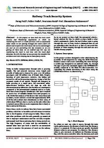
Dynamic Properties of Railway Track and Its Components: A state-of-the-art review Sakdirat Kaewunruen*, 1, 2, Alex M Remennikov1 1
School of Civil, Mining, and Environmental Engineering, Faculty of Engineering The University of Wollongong, Wollongong 2522 NSW, Australia 2
Austrak Pty Ltd, Moorooka, Brisbane, 4105 QLD, Australia
Abstract: Recent findings indicate one of major causes of damages, which is attributed to the resonant behaviours, in a railway track and its components. Basically, when a railway track is excited to generalised dynamic loading, the railway track deforms and then vibrates for certain duration. Dynamic responses of the railway track and its components are the key to evaluate the structural capacity of railway track and its components. If a dynamic loading resonates the railway track’s dynamic responses, its components tend to have the significant damage from excessive dynamic stresses. For example, a rail vibration could lead to defects in rails or wheels. The track vibrations can cause the crack damage in railway sleepers or fasteners, or even the breakage of ballast support. Therefore, the identification of dynamic properties of railway track and its components is imperative, in order to avoid any train operation that might trigger such resonances. This chapter deals with the vibration measurement techniques and the dynamic behaviours of ballasted railway tracks, and in particular their major components. It describes the concept of vibration measurements and the understanding into the dynamic behaviour of ballasted railtrack sleepers. It discusses briefly on the track structures and track components in order to provide the foundation of understanding ballasted railway tracks. The highlight in this paper is the state-of-theart review of dynamic properties of railway track and its components. It summarises the nondestructive acoustic methods, the identification processes, and the properties of each rail track element.
*
Corresponding author. Tel.: +61 7 3308 7608; fax.: +61 7 3308 7881. E-mail addresses:
[email protected] (S. Kaewunruen),
[email protected] (A.M. Remennikov)
Key words: Dynamics; Acoustics; Concrete sleepers; Rail pad; Ballast; Railway track; Non destructive test; Vibration measurement; Property.
1.0 General background Structural dynamic problems result in a serious failure and design restriction over a wide range of engineering structures since natural phenomena and human activities often impart time-dependent burden on every accessible structures. Analysis and design of those structures are based on the consideration of dynamic actions. The dynamic parameters of those structures, such as natural frequency, damping constant, and corresponding mode shape, are of substantial importance in the procedures needed for analysis and design of such structures subjected to dynamic loadings. Consequently, it is inevitable to investigate the dynamic and acoustic properties of an object associated with various sources of noise and vibration. In general, the major outcomes of the vibration measurements are the natural frequency, the dashpot value and the mode shape. Apart from explicit properties, the dynamic stiffness can be extracted and estimated from the vibration responses of structures. The principal reason of the dynamic test is that those outcomes allow verifying an analytical model proposed for the system tested. The analytical model, which has been validated, can be used in design and response prediction with much confidence. It forms a new arena in engineering trials as a ‘virtual experiment’. However, the structural modifications in computer simulations could yield further sensitivity analysis whereas either linear or nonlinear behaviour can be identified though the experimentations. Enormously, railways have taken major part in transporting population, resources, merchandises, etc. over the large continent of any country. Railway industry has significantly grown in the past century and has continuingly developed new suitable technology for its solution to specific requirements. In many countries, the traditional railway system is the ballasted track, which consists of rails, rail pads, and concrete sleepers (ties) laid on ballast and subgrade. Recently, the demand of track usages has greatly increased. The increase in frequency of traffic for passenger trains and the rise in loads of freight trains over recent years have also been a significant factor
contributing to the deterioration of the railway track system. The increase in transport capacity has been stimulated by the growing industrial need for long-distance freight conveyancing, especially in large countries with lots of coalmines like Australia or China. It was evident that railway tracks in Australia have been deteriorating due to increased traffic frequency, heavier wheel loads and improper maintenance. However, undetermined ultimate load capacity of track components has been under suspicion in order to specify a reserved performance in each particular track component. Regardless to a nature that railway tracks are subject to impact dynamics induced by wheel/rail interaction or irregularities, railway civil engineers have paid attention to the real capacity of track components under realistic load. This has been a recent attempt to develop the advances in design of such infrastructure. At present, many research organizations rigorously aims at providing rail track owners/designers the up-to-date knowledge related to the dynamic behaviors of prestressed concrete sleepers, rail pads, and other track components. Based on the fact that the rail firms do run their own business, a number of projects attempts at giving chances to them for making use of their existing railway structures more efficiently and in particular more cost-effectively. However, the limited information on static and dynamic behaviors nowadays still indicates the methods and procedures of over- analysis and design of such rail structures as concrete sleepers and railway track components. In order to either improve those economical analysis and design or exploit the applicable capacity from existing structures, the better realistic insight of static, dynamic, and impact responses must be ascertained. For instance, the Australian Cooperative Research Centre for Railway Engineering and Technologies (RailCRC) has been constituted based on the awareness of those problems in Australia. Its mission is to become an internationally recognized National Research Centre for the Australian Railway Industry and to deliver decision-making tools, knowledge and technologies necessary to address industry needs for the effective rail management, operation, maintenance and development of the rail industry. To accomplish this mission Rail CRC promotes several research
projects in coordination within six industry partners and six universities. A research investigation under a funded project of Rail CRC No.5/23 was “Dynamic analysis of track and the assessment of its capacity with particular reference to concrete sleepers”, which had been allocated into a Research Theme # 2 “Innovative Track Maintenance and Upgrading Technologies”. The University of Wollongong (UoW)’s contribution to the project had included the integration of experiments and simulations with reference to concrete sleepers and railway track, and the development of a new limit states design philosophy of concrete sleepers, with close relation to computer package for track analysis and factored load analysis done at Queensland University of Technology (QUT). In this chapter, the technical procedures and testing methodology for dynamic characteristics of such track components as rail bearing pads, prestressed concrete sleepers, and ballast/subballast/subgrade have been reviewed and summarized. The ballasted track system and the wellknown modal testing technique have been briefly described.
Previous analytical model and
experiments of rail track-component vibrations have also been taken into account. Of the most interest, practical test methods in in-situ and in-field conditions are subsequently addressed.
2.0 Ballasted Railway Tracks Rail track is a fundamental part of railway infrastructure and its components can be classified into two main categories: superstructure and substructure. The most obvious parts of the track as the rails, rail pads, concrete sleepers, and fastening systems are referred to as the superstructure while the substructure is associated with a geotechnical system consisting of ballast, sub-ballast and subgrade (formation). Both superstructure and substructure are mutually important in ensuring the safety and comfort of passengers and quality of the ride. The typical shape and construction profiles of a ballasted track are illustrated in Figure 1.
Figure 1. Typical ballasted track profile
2.1 Rails Rails are longitudinal steel members that are placed on spaced sleepers to guide the rolling stock. Their strength and stiffness must be sufficient to maintain a steady shape and smooth track configuration (Selig and Waters, 1994), and resist various forces exerted by travelling rolling stock. One of their primary functions is to accommodate and transfer the wheel/axle loads onto the supporting sleepers. Esveld (2001) reported that a modern rail track also conveys signals and acts as a conductor on an electrified line. Adoped from Esveld (2001), Table 2.1 describes typical rail profiles and their applications. The most commonly used profile is flat-bottom rail, also called Vignole rail, and is divided into three parts: - rail head: the top surface that contacts the wheel tire - rail web: the middle part that supports the rail head, like columns - rail foot: the bottom part that distributes the load from the web to the underlying superstructure components.
Table 1 Types of rail profiles and their applications (Esveld, 2001). Shape
Profile type:
Applications:
Flat-bottom rail
Standard rail track
Construction rail
Manufacturing of automobiles and switch parts
Grooved rail
Railway track embedded in pavements, roads, yards
Block rail
Railway track used in concrete slab as part of Nikex-structure
Crane rail
Heavy load hoisting cranes with high wheel loads
2.2 Fastening Systems The fastening system, or “fastenings,” includes every component that connects the rail to the sleeper. Fastenings clamp the rail gauge within acceptable tolerances and then absorb forces from the rails and transfer them to the sleepers. Vibration and impact from various sources e.g. traffics, natural hazards, etc. are also dampened and decelerated by fastenings. Fastenings sometimes act as electrical insulation between the rail and the sleepers. Their primary components are fastener and rail pad. Some tracks might have base plates with or without pads, which helps the workmen to remove
damaged rails without having to untie the fastenings and immediately replace them with new rails. In this case the rail is only connected to the immediate base plate. This system is called indirect fastenings, which differs from the usual direct fastenings in that the latter device is built-in and holds the rail directly onto the sleepers (Esveld, 2001; Smutny, 2004). A typical concrete fastening system is shown in Figure 2.
Figure 2. Typical fastening system for concrete sleepers (Steffens, 2005)
2.3 Fasteners Because there are many different types of fasteners, their application depends on the characteristics, patterns, and structure of the sleepers to be used. The fasteners withstand the vertical, lateral, and longitudinal forces, and overturning moments of the track, as well as keeping the rails in place. They also transfer all the forces caused by the wheels, thermal change, and natural hazards, from the rails to the adjacent sleepers.
2.4 Rail Pads Rail pads are placed on the rail seat to filter and transfer the dynamic forces from rails and fasteners to the sleepers. The high dashpot value of rail pads reduces excessive high-frequency forces and provides a resiliency between rail and sleeper that helps alleviate rail seat cracking and contact attrition.
2.5 Sleepers Sleepers are transverse beams resting on ballast and support. Wooden sleepers were used in the paste because timber was readily available in the local area. However, pre-stressed or reinforced concrete sleepers, and to a limited extent steel sleepers, have been adopted in modern railway tracks over the past decades because of their durability and long service life. Esveld (2001) grouped timber sleepers into two types: softwood (e.g. pinewood) and hardwood (e.g. beech, oak, tropical tree). Concrete sleepers are described as either twin-block or mono-block (FIP Commission on Prefabrication, 1987), and are illustrated in Figure 3. Within all these types, concrete sleepers are more widely used because they are not affected very much by either climate or weather. The important functions of sleepers are: - To uniformly transfer and distribute loads from the rail foot to the underlying ballast bed; - To provide an anchorage for the fastening system that holds the rails at their correct gauge and preserves inclination, and - To support the rail and restrain longitudinal, lateral and vertical movement by embedding itself onto the substructures.
a) monoblock concrete sleeper
b) twin-block concrete sleeper
Figure 3. Types of concrete sleepers
2.6 Ballast Ballast is a layer of free draining coarse aggregate used as a tensionless elastic support for resting sleepers. This layer comprises graded crushed stone, gravel, and crushed gravel such as granite and basalt which depends on local availability. It not only provides support, it also transfers the load from the track to the sub-ballast and drains water away from the rails and sleepers. For a heavy haul freight line, individual axle loads on rails can be up to 50 tons or around 80 tons. Thus, in addition to the weight of the track, heavy cyclic loading, tamping and impact from rolling stock, ballast provides a static and dynamic stability to the sleepers by distributing a uniform load and reduction over the sub-ballast and subgrade. The fundamental functions of ballast can be summarised from previous research as follows (Hay, 1982; Selig and Waters, 1994; Esveld, 2001). • Resist vertical, lateral and longitudinal forces applied to the sleepers, to retain the track in its proper position because the submergence and interlocking of irregularly shaped ballast tends to confine the sleepers, as shown in Figure 4.; • Absorb shock and impact from the rough interlocking particles acting as a simple spring element with limited action; • Give resiliency and energy absorption to the sleeper; • Assist track maintenance in surfacing and lining operations (track geometry adjustment and sleeper replacement) by the ability to manipulate ballast with low energy tamping; • Reduce bearing stresses from the sleeper to acceptable stress levels for underlying layers; • Allow optimum global and local settlement; • Provide some large voids for controlling the storage of internal fouling materials enable small particles to pass through; • Provide fast drainage of fluid; • Avoid freezing and thawing problems by being unsusceptible to frost;
• Provide an insulating layer with some electrical resistance; • Prohibit vegetation growth because of unsuitable cover layer for vegetation • Absorb airborne noise from travelling traffic, and • Facilitate reconstruction of the track.
Figure 4. Typical construction of a ballasted track
2.7 Sub-ballast Sub-ballast that may be called the capping layer is a layer of granular material between the ballast and underlying subgrade. It is generally composed of broadly graded slag or crushed aggregate, although a broadly graded sand-gravel compound is sometimes used. Sub-ballast is usually impervious and therefore its general functions are to: • Reduce stress at the bottom of the ballast layer to a reasonable level for the top of the subgrade; • Prevent inter-penetration from the upward migration of fine particles from the layer of subgrade to the upper layer of ballast; • Provide good drainage that is ascribed to the non-obstructed voids by inter-penetration; • Also act as a shedding layer to keep water away from subgrade; • Protect the subgrade from attrition by the hard ballast; and • Inhibit freezing and thawing problems in the subgrade.
2.8 Subgrade
Subgrade is also referred to as the formation. It includes the existing soil and rock, which possess slopes, verges, ditches and other structures or materials within. The subgrade is the last support which bears and distributes the dynamic loading resultant downward along its infinite depth. This deep layer must have sufficient bearing capacity, provide good drainage and yield a tolerably smooth settlement in order to prolong track serviceability. Some synthetic materials such as geotextile, fabric, etc., have recently been used to upgrade the capacity of the subgrade.
3.0 Modal Testing Experimental modal analysis (EMA) or modal testing is a non-destructive testing strategy based on the response of structures to vibration. Since the 1940s, modal testing has been widely used to help understand the dynamic behaviour of structures. The original modal testing technique was based on the simple sine dwell method. After some years, innovations based on Fast Fourier Transform (FFT) have been developed and are currently used (Brown, 1982; Allemang and Brown, 1986; Mitchell, 1986; Allemang, 1993; Ewin, 1995; He and Fu, 2001). This vast improvement of modal analysis results in the more precise and accurate vibration measurements. In addition, the integration of analytical models and experimental results has led to the sensitivity analysis of structural behaviour. To solve dynamic problems or analyse and design structures, experimental modal analysis becomes one of the most significant methodologies. It promises civil/mechanical engineers practical procedures and a prompt and reasonable solution to structural dynamic problems. Numerous researches have been investigated from the modal analysis perspective and have shown substantial efficiency in engineering uses, even if the modal analysis is comparatively young. Assumptions involved in modal testing include the linearity of structures, time-invariant structural parameters, and observability in measurements (Allemang, 1993). It is noteworthy that linear systems mean that the superposition of forces can be applied, although linearity may be inapplicable for some structures (Zaveri, 1985). Besides the time invariant properties mean that structural
parameters such as stiffness and damping remain constant, depending on factors excluded in the model, during a time. Observability arises when the input-output measurements have sufficient information to create a characteristic model of the structure, although the forcing and response functions must be measurable for the structure to be observed. In additional to the generic assumptions, there are five more options to be assumed when one performs an excitation on a structure. They are whether the excitation is impulsive; or white noise; or a step; or a Wiener-Levy signal; and or that there is no excitation (free decay or free response) (Allemang and Brown, 1986). Various methods for performing experimental modal analysis had been categorised by Allemang and Brown (1986) into: • Forced-normal-mode excitation, • Frequency response function, • Damped complex exponential response, and • Mathematical input-output model The forced-normal-mode function method is the oldest modal testing approach that uses multiple inputs to approximate the modal parameters but it does not take the complex modes of vibration into account.
The frequency response function (FRF) method is currently the most
common one to use for assessing modal parameters. It contains spectra computed from the autospectrum and cross-spectrum that are measured from the structure. The damped complex exponential response method makes use of the information acquired from the free decay of a system, which is generated by the release of an initial condition. There are two similar approaches, which occur through the development of a damped complex exponential response method. They are the Ibrahim time domain method and Poly reference approach. • The Ibrahim time domain (ITD) method uses data received from the impulse response function (IRF) to identify the modal parameters of a structure. This approach requires the response measurements simultaneously at a number of locations on the structure. However, a universal position can be chosen for measurements if multiple data collection
is unobtainable. Then the displacement and acceleration, or velocity of free response data is used to form the eigenvalue matrix to be solved (He and Fu, 2001). • The poly reference approach uses FRF data from multi-input multi-output testing to carry out the natural frequency, modal constants and damping loss factors. All data measured simultaneously are used to identify the modal frequencies (Allemang and Brown, 1986). The mathematical input-output model method considers the input and output responses independently. Applications can be extended to both time and frequency domain models with no limitation in the number of degrees of freedom (dof). The approaches based on this methodology are the auto-regressive moving average approach and the reduced structural matrix approach. • The auto-regressive moving average approach makes the excitation assumption that the responses obtained at various points are induced by white random noise input to the structure. The two-stage least square method is needed. From statistical results, the confidence factor (coefficients of variation), which are the ratio of the standard deviation of each parameter compared to its real counterpart, can be computed for natural frequencies and damping (Allemang and Brown, 1986). • The reduced structural matrix approach is based on the condensed matrix obtained from incomplete responses. However, its estimated solution is not unique, and the frequency range is reduced because the matrix is weighted to represent an incomplete model. Besides, the sensitivity needed to reduce the matrix will be decreased due to the limited precision of modal results from experimental errors. As a result, this method is not very successful (Allemang and Brown, 1986).
4.0 DYNAMICS OF RAIL PADS The standard rail pads used in the Australian track system are usually made from polymeric compound materials. They are installed on rail seats to reduce the dynamic stress from axle loads and wheel impact from both regular and irregular train movements. These pads are highly important
because of their dynamic softening between track and sleepers. Inappropriate or inadequate uses of rail pads exacerbate the cracking of sleepers at rail seats. Besides, misuse causes high settlements of global and local tracks, and ballast/subgrade breakage from heavier tamping (Kaewunruen and Remennikov, 2004). This negative effect can be extended to the capacity and integrity of a railway system unless this helps to gain a better understanding of the structural behaviour of them. Based on these grounds Australia has launched a standard referred to as AS1085.19 for testing bearing pads. (Standards Australia, 2001). The dynamic behaviour of rail pads is not well known, although some publications can be found, as presented: 4.1 Linear and nonlinear model of rail pads Many investigations have been carried to describe the dynamic behaviour of rail pads mathematically; they are either linear or nonlinear models. Dynamic rail pad models are usually on the fundamental basis of either time or frequency domain. The literature review shows that most are in relation to the frequency domain because this model implicates dynamic properties such as resonant frequencies and damping (Fahey and Pratt, 1998). A suitable linear ‘Fractional derivative model’ was developed by Fenander (1997; 1998) and adopted into a linear track model. In this approach the rail pad model had to be linear. Various damping or viscoelasticity models were included; for example, the viscous model where the loss factor is proportional to frequency. Since the stiffness of a rail pad is nonlinearly dependent on the preload and the fractional derivative model is linear, a different set of parameters, which were fitted to the experimental data, was needed for each preload. This model seems to be a good fit, especially for testing the stiffness of the rail pads. Sjoberg (2002) developed a time domain model, which uses compressive actions as component forces and accounts for the effect of pre-load, and the frequency and dynamic amplitude dependence. The nonlinear shape factor, neo-Hookean hyper-elastic model, fractional derivative element model, and Coulomb forcing function were included in the proposed model. It is a one
dimensional component model using a few parameters whilst giving reasonably measured characteristics. It was proposed initially for rubber isolators but could for other rubber elements. Since the complex properties of rail pads are frequency dependent, Knothe et al. (2003) developed a frequency domain model which assumed that for each frequency the equivalent complex stiffness can be approximated by a bi-linear function associated with load amplitude and preload. The latter assumption is that the modal parameters rely linearly on the frequency. The estimated values fitted the measured results quite well. 4.2 Dynamic testing of rail pads The dynamic testing of rail pads has been of interest for many years and many different methods have been developed to determine their dynamic properties. The response of a rail system comprising a concrete sleeper, rail section, and various types of rail pads to vibration were measured (Ford, 1988b) and a series of FRFs was presented to identify the effects that various pads had on the wave signals. Several types of resilient rail pads with various materials and different surface profiles had been tested in the laboratory and on a track (Grassie, 1989). The average attenuation of the pads was indicated and the results from the laboratory showed that they were conservative. Their dynamic stiffness increases with normal load and is more than or identical to the tangent stiffness from the load deflection curves. Although rail pad damping has almost no affect on the dynamic behaviour of a well compacted ballasted track, more damping causes the pad itself to heat up. Van’t Zand (1993) used FFT technique to measure and assess the dynamic characteristics of pads through impact load tests. The curve fitting method was used to fit an SDOF equation of motion to the experimental results. It was carried out at a specific frequency of 400-2000 Hz. The results was compared with another research and seemed to be in a good agreement. This method was then extended to the urban track structures (Esveld, 1997; Esveld, Kok, and De Man, 1998). Later, Fenander (1997) studied the vertical stiffness and damping of studded rail pads on a complete track and in a laboratory test rig. Stiffness increased substantially with preload but only
weakly with frequency. The fractional derivative model of their dynamic behaviour was presented in this investigation. The 2DOF testing apparatus was developed from research done by Verheij (1982). It consisted of two steel blocks with the resilient element mounted between them. To approximate the dynamic stiffness of the pads, the stiffness of the lower spring supporting the lower block was neglected. The measurements of several new pads indicated that stiffness tends to increase slightly with frequency whilst the effect of the preload is more pronounced. Thompson et al. (1998) developed an indirect method for measuring the high frequency dynamic stiffness of resilient elements by applying the theory of two-degree-of-freedom (2DOF) system. The resilient element was mounted between two large blocks on a floor, one of which was supported by soft springs beneath it. The resilient element was assumed to be much stiffer than the soft springs. Two exciters were used in the measurement apparatus and some approximations were made to reduce some difficulties with the 2DOF system. This proposed methodology can be extended to elements with low frequency stiffness by rearranging the equations of motion. The results of this case study seem to be reliable and it is noteworthy that this approximated method is being included in international standards. Another rail pad tester has been constructed based on the SDOF viewpoint, to examine their dynamic properties in controlled conditions in the laboratory (De Man and Esveld, 2000; De Man, 2002). New and worn pads were tested in the laboratory. They are considered to be the only elastic components in the tester, which is an apparatus of tuned masses, preloading springs and elastic supports. In this investigation the 2DOF-based tests on real track had also been done. However, it is noteworthy that this tester gives realistic results and becomes a better way for determining their properties. There has been a recent investigation by Knothe et al. (2003) dealing with the measurement and modelling of resilient rubber pads. The quasi-static and dynamic measurements were done in the low frequency (0-40 Hz.) and high frequency range (100-2000 Hz.). With dynamic testing two pads are placed between three steel plates which then introduces the secant, tangent and equivalent
stiffness. This test showed that the stiffness of the pads are frequency dependent and thus conform to previous researches. They were also hinged on the preload and amplitude of the harmonically varying load. It can be concluded that the equivalent stiffness increases with increasing preload and decreasing amplitude. These tests showed the hyper-elastic action of the rubber in the quasi-static test, its visco-plastic action in the low frequency cyclic load test, and especially its viscoelastic action in the high frequency range test. At the UoW an alternative method for determining the dynamic properties of rail pads based on measuring the response to SDOF vibration has been proposed. The simplicity and reliability of this method has been shown. It proved to be a fast and non-destructive method for accurately assessing the dynamic stiffness and damping constant of every type of rail pad available in Australia. This strategy enables new types of rail pads to be tested as well as evaluate how ageing affects their dynamic characteristics (Kaewunruen and Remennikov, 2004).
5.0 VIBRATIONS OF CONCRETE SLEEPERS Apart from the rail pads, concrete sleepers have also played a crucial role in this country for many years. Many investigations dealing with the dynamic properties of concrete sleepers have been performed, modal testing in particular (Ford, 1988a). Ballasted track can be divided into five groups of discrete support models (Knothe and Grassie, 1993), as shown in Table 2. To get a better insight into the dynamic strength of sleepers, their response to various dynamic loadings has been studied (Grassie and Cox, 1984; Esveld et al., 1996; De Man, 2002). Standards Australia (2003) developed AS1085.14 for analysing and designing concrete sleepers, including procedures for sampling and testing materials. It also contains the methods for testing static, quasi-static, and dynamic cyclic loading and the allowable limits and serviceability of sleepers. Modal testing has been very significant as a method for non-destructive dynamic testing of concrete sleepers for over five decades. Ford (1988a) performed a modal analysis on a concrete
railway sleeper. It was suspended at each end by soft springs which allowed for “free-free” support. An electro-dynamic shaker was used to excite the sleeper at a single point, an accelerometer was used to measure the response at the remaining points, and then a series of FRFs were obtained. In this test the natural frequencies and corresponding mode shapes were extracted using modal analysis software (SMS modal). Vincent (2001) carried out modal testing and numerical modelling of a reinforced concrete sleeper. It was laid on a very soft spring support and excitations were done with an impact hammer and a swept sine loading of a shaker with different load amplitudes. Different types of modal parameter extraction methods were used and showed that linear behaviour arises in the low frequency range but is less in the higher frequency range. Also, a 3D linear finite element model was developed by I-deas to compare the experimental and numerical results. However, excluding the steel reinforcement, the model only contains sleeper geometry with the material property updating with modal testing results. A comparison of those results shows good agreement. A sensitivity analysis was done by modifying the structural properties. Various boundary conditions such as free-free, perfectly coupled to the subsoil, and voided sleepers, were investigated for their effects on the dynamic behaviour of concrete sleepers (Plenge and Lammering, 2003). Excitations were given laterally and vertically. FRFs were obtained and became a means to study the effects of various boundary conditions on their response to vibration. A numerical investigation was done and if the sleeper was modelled as a rigid beam the results were not very good but by using the thin layer method, the simulated FRFs coincided with the measured results much better when the frequency was up to 2000 Hz. Additionally, a static load on a sleeper increases the bond with the ballast to stiffen the whole system. These experiments confirmed the results observed by Wu and Thompson (1999).
Table 2 Discrete sleeper support models Models
Assumptions Type A - discrete sleeper support - ballast: spring and damper
Kb
Cb
Type B - discrete sleeper support - half-space modeling of ballast and substrate
Type C - discrete sleeper support - ballast: spring and damper - interconnected ballasted masses - substrate: spring and damper
Type D - discrete sleeper support - continuous ballast layer - half-space substrate model
6.0 DYNAMICS OF RAILWAY TRACKS Timoshenko (1926) was one of the first to model the dynamic behaviour of a railway track. In that model, the rail was considered as an infinite uniform Euler beam, laid on a continuous damped
elastic Winkler foundation. Grassie (1982) then found in some experiments that there are only two dominant resonances in the frequency range of interest. The first in-phase mode at about 100 Hz corresponds to the sleeper and rail moving together on the ballast while the second out-of-phase mode at a frequency somewhere between 300-500 Hz depending on the rail pad parameters, corresponds to the opposite vibration of sleepers on ballast and rails on the rail pad. The dynamic moment and impact attenuation were subsequently observed. It was concluded from much research that a rail pad which was resilient at frequencies of several hundred Hertz would substantially reduce the dynamic loads on concrete sleepers. Some rail pads attenuate dynamic bending strains in concrete sleepers by more than 50%. Their stiffness has a greater effect on reducing strain in a sleeper than its depth (Grassie, 1988). The dynamic loading on sleepers was also studied and revealed that when ballast is packed loosely, the dynamic loads become significantly higher and the resilient pads have less effect. Selig and Waters (1994) studied the ground formation of a railway track was and found that the subgrade is the one component of the substructure that has the greatest affect on track stiffness. Raymond (1978) also found that stiffer tracks have smaller differential settlements or unevenness and cause lower impact loading. Coincidentally, Liang and Zhu (2001) found the lower subgrade stiffness leads to greater elastic deformation and less stability of the ballast layer and upper part of the track structure. In-situ and in-field experiments for determining global ballasted track were mostly done using the instrumented impact hammer technique because an impact hammer is mobile and selfsupporting (De Man, 1996) and can be used without damaging or obstructing traffic. The FRF measurements can be obtained through a handy laptop and immediately extracted for such modal properties as resonant frequency, damping constant, and corresponding mode shape. However, these parameters are susceptible to factors such as duration of pad usage, temperature, and preload (Wu and Thompson, 1999). Previous investigations are summarised below.
6.1 Track behaviour
Railway track modeling has only been developed in recent years to incorporate dynamic load effects. However, a more comprehensive dynamic load modelling to allow more accurate prediction of track degradation and associated railway track maintenance requirements is highly demanding. In practice, the physical railway track has historically been employed as a mechanical model to perform technical analyses. The model is rather simplistic as it could reasonably predict global track responses but the individual component’s behaviour. De Man (2002) classified railway track structures into three types: ballasted track structures, slab track structures and embedded rail structures. This chapter focuses on the ballasted type (see Figure 5) as the behaviour of the track structure depends heavily on the type of structure.
Figure 5 Railway ballasted track components
In most of mechanical models of railway tracks, the track components have been simulated as a type of elements which are classified according to their properties as follows: •
Components with mass and inertia properties, rail and sleepers;
•
Components with elastic properties, railpads; and
•
Component with mass, inertia and elastic properties; ballast.
The ballasted track structure dynamic responses vary largely on individual component properties, the contact relationship between components, the physical body of the components, and the dynamic load actions. Rail and sleepers with mass and inertia properties tend to keep the track stable under
static longitudinal buckling forces. Rail pads and ballast with elastic properties soften energy transfer and dampen the dynamic force frequency, resulting in a lower and less harmful load action. However, it is important to note that in a well-ballasted track structure, the rail pad does not damp vibration of the sleeper and plays insignificant role in softening transient load action (Kaewunruen and Remennikov, 2008); in contrast, the greater is the rail pad damping constant, the more effectively are dynamic forces transmitted to the sleepers (Grassie and Cox, 1984). It was also found that if the ballast damping is much greater than 100kNs/m, which is typical of well-compacted ballast, the railway track dynamic behaviour is affected little by rail pad damping (Grassie, 1988). Generally, the vehicular imposed loading on a railway track can be divided into three categories corresponding to the plane of loading: vertical, lateral and longitudinal. The vertical loading on the track structure consists of the static axle weight of the freight vehicle and any additional dynamic augments (e.g. quasi-static, dynamic ride, impact), which are superimposed onto this static load. These dynamic augments are often the impact load caused by a variety of defective factors, such as: •
Irregularities in the geometry of the track structure;
•
Irregularities on the surface of the rail;
•
Irregularities on the surface of the wheel;
•
The vehicle operating speed; and
•
The mass of the vehicle suspension characteristics (sprung vs unsprung mass).
Due to the physical nature of track structures, a chain of their structural vibration modes exists depending on the resonant frequencies on the vertical, lateral and longitudinal direction. The lowest possible vertical resonant frequency of the track structure is the full track resonance (ft), which includes both in-phase and out-of-phase vibrations (Kaewunruen and Remennikov, 2007). For ballasted railway tracks in generally good conditions, these full track resonant frequencies are
between 40 and 140 Hz, second vibration mode are between 100 and 400 Hz, and third vertical vibration mode are between 250-1500 Hz. Figure 6 shows the typical full track vibrations.
Figure 6 Full track vertical resonant frequency mode shape
In addition, there exists the rail resonant frequency (fr) whereas the rail vibrating to the supports and is highly dependent on the rail pad properties but is independent to the sleeper and ballast properties, as shown in Figure 7.
Figure 7 Rail resonant frequency mode shape
The vibration modes and shapes are dependent on the sleeper support spacing. As a result, the vertical vibrations with less inflection points (see Figure 7) are more likely to develop than others. These vibration modes are so-called ‘pin-pin’ resonant modes, corresponding to pinpin resonant frequencies. The first pin-pin resonant frequencies (see Figure 8) occur between 400-1200 Hz and the second (see Figure 9) at slightly less than 4 times higher frequencies.
Figure 8 First order pin-pin resonant frequency mode shape
Figure 9 Second order pin-pin resonant frequency mode shape Kaewunruen and Remennikov (2007) reported that the frequency range (low, mid and high) has varying effects on the railway track as a structure and on each component. Low frequency range (0-40 Hz) produces damage to the substructure (subgrade, sub-ballast and ballast); mid frequency range (40-400 Hz) produces damage to the superstructure excluding the rail (sleepers, fasteners, and railpads) and high frequency range (400-1500 Hz) produce damage to rails and distortion to fasteners. Also, either rail corrugation, wheel defects (e.g. wheel flats), or combination of both, may generate periodical loading through impact, creating a damaging cycle process (Remennikov and Kaewunruen, 2007; Kaewunruen, 2007). Lateral instabilities are a function of the vehicle characteristics and speed. The lateral forces on the rail are mostly located at the inner side of the railhead. In addition, lateral torsion modes can be observed at high frequencies. The lateral forces on the track structures are introduced by: •
The curvature of the freight equipment;
•
The development of lateral instabilities; or
•
The response of the vehicle to lateral track irregularities.
In terms of vibration, the longitudinal vibration modes are best interpreted as compression waves within the rails. They considerably affect the fatigue strength in minor axis of the rails, apart from loosening the fastening systems. It should be noted that the track substructure has a direct influence on the dynamic wheel load, dynamic track stiffness, and track roughness (Esveld, 2001). The substructure components also have a very strong non-linear stress-strain and breakage relationships with non-homogeneous properties (Indraratna and Salim, 2005).
Nevertheless, the most important duties of the track
substructures are: •
Distributing the dynamic load from the sleepers to the ground;
•
Supporting and anchoring the track structure;
•
Providing suitable drainage;
•
Reducing the severity of frost action on the soil; and
•
Providing resilience for the track system. Hay (1982) found that the majority of the track failures and maintenance cost are ascribed to
the track substructures (especially ballast and subgrade). These have raised the concern to observe static and dynamic behaviours of the substructure whereas many theories and methods have been developed (Indraratna and Salim, 2005). The triaxial testing method has been a very successful way of obtaining dynamic characteristics of the ballast and subgrade materials. The test identifies fundamental properties of ballast and subgrade materials such as resilient or elastic behaviour, plastic or permanent strain, breakage, and failure stress level. These properties are imperative for track substructure design and maintenance scheme (Lakenby, 2006).
6.2 In-situ dynamic testing An in-situ dynamic test was done by Ford (1988b) to determine how systems comprising a concrete sleeper, rail section, and rail pads respond to vibration. In a laboratory, a sleeper was embedded in ballast contained by a wooden box on a concrete floor. The tests were done using an electro-dynamic shaker to excite the top surface of the rail in the frequency of 0-1000 Hz. The frequency of vibration of the rail at the same point and at three points near the rail seat, were measured by the accelerometers. Sadeghi (1997) observed that by performing modal testing, the natural frequencies obtained from a test on individual concrete sleepers in the laboratory are higher than those obtained from the in-situ track test bed. These results could indicate that ballast and subgrade cause a slight reduction in the natural frequencies of sleepers. It was also found that the components of the substructure have a very strong non-linear stress-strain relationship and non-homogeneous properties.
Plenge and Lammering (2003) developed full scale laboratory experiments in order to measure the dynamic behaviour of a segment ballasted track and its constituents. The effects of voids between the sleepers and underlying ballast were considered, especially in the partially unsupported sleepers. The two kinds of voided sleepers tested were limited to sleepers with a hovering end and with 2 sided hovering ends. The dynamic displacements were measured by the holographic interferometry in addition to the common accelerometers. The results of these experiments agreed with the field data from the previous record. It also showed that deviations from coupling to the subgrade lead to remarkable changes in the dynamic behaviour. Until now, very few investigations have been conducted to study the dynamic interaction between the ballast and railway track, or its components such as sleepers, adjacent sleepers, and global systems connected by the rail track. Therefore, at the UoW, there are a number of investigations into the dynamic interaction of ballast and sleeper with various types of realistic voids and pockets in a ballasted track system, with varying wet/dry properties and static preloads (Kaewunruen and Remennikov, 2004; Remennikov and Kaewunruen, 2005).
6.3 Field trials Apparently the field trials seem to be the most realistic ones because there are no standard methods currently accepted by the industry for determining the dynamic parameters of track components required to successfully model their dynamics. The industry does not have methods for investigating dynamic parameters and responses. Instead, designers usually calculate the dynamic response based on the static loading specified in the Australian Standards and apply factors that incorporate dynamic loading. Nevertheless these experiments may lead to extremely unreliable results due to unpredictable problems in the rail track itself, e.g., the nonlinearity attributed to voided sleepers, rail impurities, corrugation, worn pads, voided sleepers, and so on. Grassie (1989a) investigated the properties of a number of rail pads with different materials (synthetic and natural rubber, plastics, and composites) and surfaces (plain, grooved and studded
surfaces), to find that the relative correlation coefficients of the relationship between data in a laboratory and on the track, were reasonable. The fractional impact attenuation of a particular pad in the field relies considerably on track conditions, and the amplitudes of dynamic and quasi-static loads. It was shown that the impact test is a good, conservative method for determining its performance. De Man (1996), and De Man and Esveld (2000) carried out the in-field trials to determine dynamic track properties by using excitation hammer testing. In this test the track was simplified as a 2DOF, discretely supported continuous rail system representing two effective masses of rail and sleeper, as well as two dynamic stiffness and two dashpots of rail pad and ballast-formation, respectively.
Based on FRF measurements and FFT, the modal parameters of the track were
extracted by an automatic curve fitting optimisation procedure. In the test example two resonance frequencies were clearly obtained and the first ‘pin-pin’ resonance was noticed in the FRFs measured. In 2002 Colla et al. combined several techniques for a site investigation of non-ballasted railway tracks. The radar technique was used for the layer interface bonding tests, ultrasound helped detect the contact conditions between sleepers and subgrade, and an impact echo technique played a vital role in investigating the structural integrity of those tracks. However Knothe et al. (2003), reported that the values obtained from the field could only be reliable in the frequency range of the second resonance peak. These field measurements could be obtained when: •
The excitation of a train travelling on the track can be measured;
•
A shaker can be used to excite the rail; and
•
A calibrated impact hammer can be successfully used to hit the rail.
At the UoW two 2DOF models have been developed based on the FFT analysis and mode superposition method to extract the dynamic properties of ballasted track systems. Responses to ambient vibration induced by normal traffic from the Lara site in Victoria are recorded by a CRCRail project. The signal analyses are being done to extract the dynamic properties of the track and
field tests will be conducted to investigate more precise results (Kaewunruen and Remennikov, 2005).
7.0 SUMMARY Rail track is a fundamental part of railway infrastructure and its components are divided into superstructure and substructure. The most observable parts such as the rails, rail pads, concrete sleepers, and fastening systems are referred to as the superstructure while the substructure is associated with a geotechnical system consisting of ballast, sub-ballast and subgrade. The dynamic testing of railway tracks and its components are of interest, particularly the concrete sleepers and rail pads. In this chapter the technical procedures and testing methods for evaluating the components of ballasted track have also been reviewed and summarised. The ballasted track system and the wellknown modal testing technique have been described. Previous analytical models and experiments into the vibration of track components have also been included and practical tests methods used in the field and in situ have been highlighted. Rail pads are usually installed on rail seats to reduce the stress from axle loads and wheel impact from regular and irregular train movements. They are very important because they soften the interaction between the track and the sleepers. Several time and frequency domain modelling of rail pads had been done as well as a number of experiments of their dynamic parameters. Some investigations dealing with the dynamic properties of concrete sleepers can be found in this paper. Most are based on the experimental modal testing technique. In addition the various boundary conditions of sleepers, such as free-free, perfectly coupled to the subsoil, and voided sleepers, were investigated for their effect on the dynamic behaviour of concrete sleepers. However, some limitations still remain, as reported. Until now, very few investigations have been conducted into studying the dynamic interaction between the ballast and track or components such as sleepers, adjacent sleepers, and global systems connected by the rail track. In addition, although the field tests seem to be realistic,
the experiments may lead to extremely unreliable results due to many unpredictable problems in the track such as nonlinearity that is attributed to voided sleepers, rail impurities, track corrugations, worn pads, and voided sleepers. Acknowledgement The authors are grateful to acknowledge the Australian Cooperative Research Centre for Railway Engineering and Technologies for the financial support as part of Project #5/23.
References Allemang, R. (1993), Modal Analysis – Where do we go from here?, International Journal of Analytical and Experimental Modal Analysis, 8(2) April, 79-91. Allemang, R. and Brown, D. (1986), Multiple – Input experimental modal analysis – A survey, International Journal of Modal Analysis, January, 37-43. Brown, D. (1982), Keynote Speech Modal Analysis – Past, Present and Future, Proceedings of the 1st International Modal Conference, Union College, New York. De Man, A.P. (1996). Determination of dynamic track properties by means of excitation hammer testing, Railway Engineering International 1996 Edition, (4), 8-9. De Man, A.P. and Esveld, C. (2000). Recording, estimating, and managing the dynamic behavior of railway structures, Proceedings of Symposium Leuven. The Netherlands. De Man, A.P. (2002). DYNATRACK: A survey of dynamic railway track properties and their quality, Ph.D. Thesis, Faculty of Civil Engineering, Delft University of Technology, The Netherlands. Esveld, C., Kok, A.W.M, and De Man, A. (1998). Integrated numerical and experimental research of railway track structures, Proceedings of the 4th International Workshop on Design Theories and their Verification of Concrete slabs for Pavements and Railroads, Portugal. Esveld, C. (2001) Modern Railway Track, MRT Press. The Netherlands. Ewins, D.J. (1995). Modal Testing: Theory and Practice, Research Studies Press, Taunton.
Fahey, S. O’F. and Pratt, J. (1998). Frequency domain modal estimation techniques, Experimental Techniques, Sep/Oct, 22(5), 33-37. Fenander, A. (1997). Frequency dependent stiffness and damping of railpads, Proceedings of Institute of Mechanical Engineering Part F, 211, 51-62. Fenander, A. (1998). A fractional derivative railpad model included in a railway track model, Journal of Sound and Vibration, 212(5), 889-903. FIP Commission on Prefabrication. (1987). Concrete Railway Sleepers – FIP State of Art Report, Thomas Telford Ltd., London, UK. Ford, R. (1988a) Modal analysis of a concrete railway sleeper, Research Note AVG/RN881122-1, School of Mechanical and Industrial Engineering, University of New South Wales, Australia. Ford, R. (1988b) Vibration responses of systems comprising a concrete sleeper, rail section, and various types of rail pads, Research Note AVG/RN881122-2, School of Mechanical and Industrial Engineering, University of New South Wales, Australia. Grassie, SL., Gregory, RW., Harriswon, D., and Johnson, KL. (1982) The dynamic response of railway track to high frequency vertical excitation, Proceedings of the Institution of Mechanical Engineers, Part C, Journal of Mechanical Engineering Science; 24(2): 77-90. Grassie, S.L. and Cox, S.J. (1984). The dynamic response of railway track with flexible sleepers to high frequency vertical excitation, Proceedings of Institute of Mechanical Engineering Part D, 24, 77-90. Grassie, S.L. (1987). Measurement and attenuation of load in concrete sleepers, Proceedings of Conference on Railway Engineering, Perth, September 14-16, 125-130. Grassie, S.L. (1989a). Resilient rail pads: Their dynamic behavior in the laboratory and on track, Proceedings of Institute of Mechanical Engineering Part F, 203, 25-32. Grassie, S.L. (1989b). Behavior in track of concrete sleepers with resilient rail pads, Proceedings of Institute of Mechanical Engineering Part F, 203, 97-101.
Grassie, SL. and Kalousek, J. (1994) Rail corrugation: characteristics, causes and treatments, Proceedings of the Institution of Mechanical Engineers, Part F, Journal of Rail and Rapid Transit; 207(F1): 57-68. Grassie, SL. (1996) Models of railway track and train-track interaction at high frequencies: Results of benchmark test, Vehicle System Dynamics; 25(Supplement): 243-262. Gustavson, R. (2000), Static and dynamic finite element analyses of concrete sleepers, Licentiate of Engineering Thesis, Department of Structural Engineering, Chalmers University of Technology, Sweden. Gustavson, R., (2002). Structural behaviour of concrete railway sleepers. PhD Thesis, Department of Structural Engineering, Chalmers University of Technology, Sweden. Hay, W.M. (1982) Railroad Engineering, 2nd edition, John Wiley & Sons, Inc. He, H. and Fu, Z. (2001), Modal Analysis, Butterworth – Heinemann Publishers, Great Britain. Indraratna, B. and Salim, W. (2005) Mechanics of Ballasted Rail Tracks A Geotechnical Perspective. Taylor & Francis, London. Kaewunruen, S., and Remennikov, A. (2004), A state-of-the-art review report on vibration testing of ballasted track components, July-Dec Research Report, CRC Railway Engineering and Technology, Australia, December, 20p. Kaewunruen, S. and Remennikov, A.M., (2007), Field trials for dynamic characteristics of railway track and its components using impact excitation technique. NDT&E International, 40(7), 510519. Kaewunruen, S. (2007), Experimental and numerical studies for evaluating dynamic behaviour of prestressed concrete sleepers subject to severe impact loading, PhD Thesis, School of Civil, Mining, and Environmental Engineering, University of Wollongong, NSW, Australia. Kaewunruen, S. and Remennikov, A.M., (2008), Nonlinear transient analysis of railway concrete sleepers in track systems. International Journal of Structural Stability and Dynamics, in press.
Knothe, K. and Grassie, S.L. (1993). Modelling of railway track and vehicle/track interaction at high frequencies, Vehicle System Dynamics, 22(3-4), 209-262. Knothe, K., Yu, M.and Ilias, H. (2003). Measurement and Modelling of Resilient Rubber Rail-Pads. In: K. Popp und W. Schiehlen (Ed.), System Dynamics and Long-term Behaviour of Railway Vehicles, Track and Subgrade, Springer Verlag, Berlin Heidelberg, Germany, pp. 265-274. Lackenby, J. (2006) Triaxial behaviour of ballast and the role of confining pressure under cyclic loading, PhD Thesis, School of Civil, Mining, and Environmental Engineering, University of Wollongong, NSW, Australia. Liang, B. and Zhu D., (2001).Dynamic analyisis of the vehicle-subgrade model of a vertical coupled system, Journal of Sound and Vibration, (245), 79-92. Mitchell, L. (1986), Signal processing and the Fast Fourier Transform (FFT) Analyser: A survey, International Journal of Modal Analysis, January, 24-36. Plenge, M. and Lammering, R. (2003). The dynamics of railway track and subgrade with respect to deteriorated sleeper support. In: K. Popp und W. Schiehlen (Ed.), System Dynamics and Longterm Behaviour of Railway Vehicles, Track and Subgrade, Springer Verlag, Berlin Heidelberg, Germany, pp. 295-314. Raymond, G.P. (1978), Design for railroad ballast and subgrade support, Journal of the Geotechnical Engineering Division ASCE, 104(1): 45-60. Remennikov, A.M. and Kaewunruen, S., 2005, Investigation of vibration characteristics of prestressed concrete sleepers in free-free and in-situ conditions. Australian Structural Engineering Conference 2005, Sep 11-14, Newcastle, Australia [CD Rom]. Remennikov, A.M. and Kaewunruen, S., 2007, A review on loading conditions for railway track structures due to train and track vertical interaction. Structural Control and Health Monitoring, in press.
Sadeghi, J. (1997), Investigation of characteristics and modeling of railway track system, PhD Thesis, School of Civil, Mining, and Environmental Engineering, the University of Wollongong, Australia. Selig, E.T. and Waters, J.M. (1994). Track geotechnology and substructure management, 1st Ed., Technology Development and Application Committee, on behalf of the Railways of Australia. Sjoberg, M. (2002). On dynamic properties of rubber isolators, Ph.D. Thesis, Department of Vehicle Engineering, Kungl Teknisa Hogskolan Royal Institute of Technology, Stockholm, Sweden. Smutny, J. (2004). Measurement and analysis of dynamic and acoustic parameters of rail fastening, NDT&E International, 37, 119-129. Standards Australia, (2001). AS1085.19-2001 Railway track material - Part 19: Resilient fastening assemblies, Standards Australia. Standards Australia, (2003). AS1085.14-2003 Railway track material - Part 14: Prestressed concrete sleepers, Standards Australia Steffens, D.M. (2005). Identification and development of a model of railway track dynamic behavior, M.Eng. Thesis, School of Civil Engineering, Queensland University of Technology, QLD. Australia. Timoshenko S. (1926) Method of analysis of statistical and dynamical stresses in rail. In: Proceedings of Second Int. Congress for Applied Mechanics, Zurich, 407-418. Thompson, D.J., van Vliet, W.J., and Verheij, J.W. (1998). Developments of the indirect method for measuring the high frequency dynamic stiffness of resilient elements, Journal of Sound and Vibration, 213(1), 169-188. Van’t, Z. (1993). Assessment of dynamic characteristics of rail pads, Railway Engineering International 1994 Edition, 23(4), 15-17. Verheij, J.W. (1982). Multi-path sound transfer from resiliently mounted shipboard machinery, Ph.D. Thesis, TNO Institute of Applied Physics, Delft University of Technology, the Netherlands.
Vincent, G. (2001). Modal analysis and numerical modeling of a concrete railway sleepers, M.Eng. Thesis, Department of Structural Engineering, Chalmers University of Technology, Göteborg, Sweden. 128 pp. Wu, T.X. and Thompson, D.J. (1999), The effects of local preload on the foundation stiffness and vertical vibration of railway track, Journal of Sound and Vibration, 219(5), 881-904. Wu, T.X., & Thompson, D.J. (2004) The effects of track nonlinearity on wheel/rail impact. Proceedings of the Institution of Mechanical Engineers Part F: Rail and Rapid Transit; 218(1): 1-15. Zaveri, K. (1985). Modal Analysis of Large Structures – Multiple Exciter Systems, Naerum Offset, Denmark.