Dynamic Service Extensibility through Programmable Network. Robert Hsieh .... A CP is responsible for the local resource management, policing and monitoring.
Dynamic Service Extensibility through Programmable Network Robert Hsieh, Aruna Seneviratne School of Electrical Engineering and Telecommunications The University of New South Wales Sydney, Australia 2052 {roberth,aruna}@ee.unsw.edu.au
Abstract There has been a tremendous interest in making the current Internet architecture capable of supporting diverse requirements for emerging valueadded service-oriented applications such as bandwidth on-demand, multimedia teleconference and telemedicine. However, to our knowledge, all of the currently proposed ‘application-level’ service architectures, for example, [7], [9], [10], [13], [16], are restricted to operate within one administrative domain, or a confederation of administrative domains. This paper addresses the following issue: Is it possible to remove the boundary that confines this closeness in operating environment and be able to extend application-level service architectures in a dynamic and on-demand manner over the Internet? We outlined a service extension framework, Dynamic Extensible and Programmable Service Architecture (DEEPSEA), which is aimed at accomplishing an extensible service framework through programmable and active networking methodology for IP-centric devices. In our framework, we discuss issues regarding service extension, maintenance, teardown control, as well as detailing an implementation design in achieving these. Keywords: Active Network, Dynamic Service Extension, Pervasive Computing, Programmable Networking Architecture, Inter-domain Quality-of-Service.
1.0 Introduction The emerging trend in network research is the offering of value-added application-level services through networking environment, such as [3], [18] and [12]. The primary concept that is common to all is the introduction of specialized service entities, strategically distributed throughout and inside the network, which provide resource adaptation, service provisioning or control functionalities along the data path. What is also common to all is that these services are confined in reachability to within a single administrative domain or a confederation of administrative domains/Autonomous Systems. (We use administrative domain and Autonomous Systems interchangeably.) In the network operator’s perspective, the problem is that for any new administrative domains that are interested in participating in service offerings, specialized service entities must be present a priori. From the service subscriber’s perspective, if he/she moves out of the service domain into a new administrative domain, the original services can no longer be warranted. Therefore, DEEPSEA is aimed at solving the following: Is it possible to extend network service environment in a way that the service boundary (maybe formed by
a confederation of administrative domains through collaboration) can be extended dynamically and on-demand, across multiple administrative domains on the Internet? Imagine a ‘borderless’ broadband VPN service, a dynamic on-demand VPN architecture without boundary restriction on the Internet. Imagine an IT consultant on the move and be able to establish a VPN back to his/her company over high speed broadband technology, anytime, anyplace with any devices. These are what DEEPSEA aims to achieve. The contribution of this paper is as follows. We define the concept of dynamic service extension for value-added application-level services. We address the issue of service provisioning/creation across multiple Internet administrative domains and more importantly how it is possible in dynamically extending such service provisioning to new administrative domains on-demand and onthe-fly. We leverage on programmable network platform technologies and Active Network execution environment in illustrating a specific implementation design of DEEPSEA framework. To our knowledge, DEEPSEA is unique in that, it is the first major work exploring the intersection between dynamic service extensibility and application-level value-added service architecture. This paper is therefore structured as follows. Section 2 describes the related work. Section 3 describes the DEEPSEA architectural elements, operation scenario, service set up, maintenance and teardown. Section 4 presents our implementation design of the programmable execution environment for DEEPSEA and we conclude in Section 5. 2.0 Related Work Some notable examples of earlier research work on adaptive application-level networking include Conductor [13], Internet Core Network Architecture for Integrated Communication (ICEBERG) [7], and Dynamic VPN [16]. Conductor is a distributed adaptation framework that consists of ‘Conductor-enabled’ nodes deployed inside an organization’s network infrastructure or ISP, in order for the dynamic installation of ‘adaptors’, in performing content adaptation. ICEBERG is a communications service architecture, that provides integrated telephony and data services spanning diverse access networks. Similarly, it is also necessary to pre-deploy ICEBERG platforms on all participating access networks, forming the ICEBERG network plane, for such integrated services to be achievable. Concepts of dynamic adaptive QoS management have also been shown with the Dynamic VPN project. With this framework, however, the basis for creating dynamic VPN is a fixed and predetermined network topology. With proper service management, dynamicity in service provisioning is achieved, though only within the predetermined/fixed network. More recently, there are many active research and development on how to provide value-added service to the next generation Internet, in particular, a competitive, informational and service oriented Internet. Sun’s Open Net Environment (ONE) and ‘Service-on-Demand’ [18] are about describing how enterprises use their IT environment, in particular the Internet, to transact and report business operations and to communicate with others. Web Services [12], a joint effort by IBM, Microsoft and many others, is about making programmable application logics accessible using standard Internet Protocol. Its aim is similar to that of component technologies such as DCOM [22] or CORBA [11] but without the object-model-specific protocols. Instead, HTTP [4] and XML [6] are used. The Open Pluggable Edge Services (OPES) [3] are services that would be deployed in the network, i.e. at a web proxy cache between the origin server and the client, that would transform and/or filter content. It is an IETF effort in addressing the architectural standardization of emerging value-added services such as content adaptation for clients with limited bandwidth, language translation and virus scanning etc.
The Service Architecture for Heterogeneous Access, Resources and Applications (SAHARA) [23] is motivated by the emerging Internet horizontal integration business model. The 3G mobile architecture and the telecommunications industry are moving from the traditional vertical integrated model to a horizontally layered architecture where service providers can operate without owning network infrastructure and network operators can survive without permanent subscribers. SAHARA assumes that the future of Internet will i) exhibit a more competitive and dynamic condition where resource allocation is through a brokering mechanism, ii) marketplaces managed by trusted third party partners, iii) efficient resource sharing and rapid development through confederation effort, and iv) a wide spread of horizontally integrated ‘multiproviders’. In contrast to all the prior researches, DEEPSEA is unique in that it attempts to address what all the above do not, namely, how to maintain and continue offering such value-added services once a subscriber leave the service operator’s ‘normal’, often rigidly fixed, administrative domain or operation networks that is bounded in service reachability. New AS Existing Service Infrustructure
Home Network EG
AS
AS
Web Switch
Execution Environment EEG
AS
PA EI
EMod
AS AS
CH
Visiting Network
Existing Network Resource Plane
Extensible Network Resource Plane
CPG
CP CP
CP
CP CP
Service Control Plane
Figure 1 DEEPSEA Framework
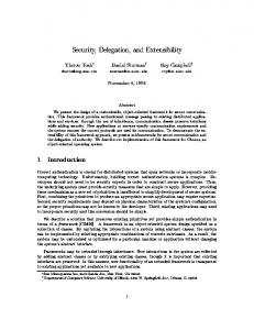
3.0 DEEPSEA Framework The DEEPSEA framework makes two pivotal assumptions about service architectures of the next generation Internet. Firstly, it assumes that the concept of ‘resource hiring’ will be widely accepted. We formally define resource hiring as the practice where certain certified entities are able to hire from a foreign administrative domain, resources, such as computation power and bandwidth, for an agreed duration, (usually no more than a few hours) with a negotiated price and transacted on-the-fly. The second assumption is that in the foreseeable future, programmable networking devices such as a Web switch [1] or those described in [19] and [20] will be widely deployed over the Internet, capable of running application program in transforming data flows. 3.1 Architectural Overview Based on these two assumptions, DEEPSEA forms a conceptual dynamic extensible service framework, by defining two logical functional planes and introduces seven generic control entities, as
shown in Figure 1. They are the Network Resource Plane (NRP), the Service Control Plane (SCP), the Control Point (CP), the Control Point Gateway (CPG), the Extension Gateway (EG), the Personal Agent (PA), the Execution Interpreter (EI), the Execution Environment Gateway (EEG) and the Extension Module (EMod). In what follows, we are to describe the relationship between these entities as well as their qualities and responsibilities, with respect to the DEEPSEA framework. The NRP consists of raw resources, such as, bandwidth, computation power etc., and is comprised of a confederation of ASs or administrative domains, forming an effective operable service boundary. The SCP consists of management nodes, each associate with the corresponding AS, co-operating together in providing service management, within the defined service boundary of NRP. Inside the SCP, we define two distinctive management node types, the Control Point (CP) and the Control Point Gateway (CPG). A CP is responsible for the local resource management, policing and monitoring inside a particular domain within the NRP. The CPG is the first point of contact for new administrative domain wishing to join the existing service architecture. It is not our goal to define specific service control architecture for DEEPSEA, but rather, we define a generalized requirement where two such control entities, namely the CP and the CPG, must exist inside the SCP in making the DEEPSEA framework operable. We define the ‘Existing NRP’ as the current service infrastructure, while the ‘Extensible NRP’ as the new domain to be merged with the Existing NRP. Within the Existing NRP, any communication host must belong to a home network. The home network contains three control entities, the Extension Gateway (EG), the Personal Agent (PA) and the Extension Interpreter (EI). The EG’s role is to provide admission control for the dynamic extensibility of the DEEPSEA architecture. The PA is a ‘servant’ entity that maintains the profile, i.e. connection state, communication requirements etc., of its associated Communication Host (CH). PA is initially located inside the home network but may migrate if necessary in following the CH. Similar to [2], the PA actively senses the surrounding network environment in providing its CH with certain level of network awareness, i.e., bandwidth limitation. The PA is a first point of contact for any host in the DEEPSEA framework wishing to request a value-added service which the service architecture provides. The deliberate separation of control logic, from the communication host (CH) to a separate entity (PA), is to provide another layer of intelligent indirection. The intelligence is ‘stored’ inside the network where the end hosts are not forced to maintain control states if necessary. We anticipate future ultra-portable network devices to be extremely ‘thin’ in computation resource, e.g. 3G cell phone or Personal Digital Assistant (PDA) based devices. In the potential Extensible NRP, it is assumed that there is a programmable execution environment, containing two other control entities: the Execution Environment Gateway (EEG) and the Extension Module (EMod). A programmable execution environment is assumed to be provided by the programmable network platform hardware, containing a run-time environment capable of resource hiring transaction activities. The EEG manages the execution environment resources. The EG negotiate with EEG in securing resources for the dynamic deployment of its EMod. The EMod is the specialized control entity, belong to a specific service architecture, used to pledge the new domain with the existing NRP and the associated SCP. The EMod essentially represents the new extensible NRP similar to that of the CP entity in the existing NRP infrastructure. A Web switch is the hardware device containing programmable networking execution environment located near the CH. Regarding resource negotiation, the EEG is responsible in advertising the resource availability. The advertisement can be implemented using modified router advertisement message with an option bit indicating resource hiring capability and maybe additional bits in indicating the applicable resource
negotiation protocol. The role of the Execution Interpreter (EI), located in the home network, is to act as an universal translator, interpreting the resource negotiation protocol in use at the new Extensible NRP. We assume that there is an information database, located somewhere in Internet, containing the semantics of all available resource negotiation protocols. The EI is able to consult such database if it does not understand any specific resource negotiation protocol. We also assume that EEG will actively register and/or update such information database, as it is in the best interest for it to ‘sell’ its available resources. Since the hirer’s intention in resource renting is unknown and the usage context is non-deterministic a priori, this generic database-interpreter protocol model is best suited. The EEG does not ‘guess’ or ‘fit’ the resource requirements of an EG, but rather, resources are determined purely through negotiation for each independent hiring event.
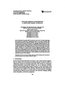
Figure 2 Extension Operation Behavior
Figure 2 shows the typical operational behavior for the service extension within the DEEPSEA framework. When a CH arrives at a new access network (obtains an IP address through DHCP for instance), it signals its PA in requesting the same value-added service that it used to receive at its home network. If the PA determines that the CH has arrived at a network domain not covered by the existing service architecture, it will trigger the dynamic extension process. In such case, the PA first sends an extension request to the EG located in the home network. The EG will send a resource negotiation message to the EEG specified by the PA. (The PA or the CH is responsible in the discovery of an programmable execution environment. We presume that the programmable execution environment will be advertised similar to that of the router advertisement [21] mechanism.) If the resource negotiation is successful, an extension acknowledgement will be send to the PA indicating that the extension process is in progress. The EG then upload the EMod to the negotiated resource space, inside the programmable execution environment, located in the new network domain. Upon upload completion, the EMod acknowledges the EG with the successful status and the EG sends an acknowledgement to the CH indicating a successful extension. Subsequently, the PA sends an initiate message containing the service requirement to the EMod. The EMod will acts as the new CP for the new network domain. It will firstly request to join with the existing SCP through the CPG node. EG
possess the knowledge of the location of CPG, and this is passed to the EMod as part of the uploading process. Once the EMod is admitted to the SCP, it will begin the service creation process and if the outcome is successful the EMod will acknowledge the PA with a confirmation message. The PA then notifies the CH that the requested service is available. a. Inter-domain Traffic Monitoring & Policing, Adaptive Traffic Aggregation b. Intra-domain Traffic Monitoring & Policing c. Admission Control d. Intra-domain QoS e. Inter-domain QoS based on adaptive aggregation f. Domain specific traffic statistics g. Association of LCP to domain(s) h. Establishing new LCP i. Association of new LCP to MCP j. Extending through EG
LCP CN
d. EG
WAN
g. h.
M CP
Source (Home) Network
i. f.
e. LCP
...
LCP
LCP
LCP
Service Control Plane
a. c. LCP
b.
d. c.
LCP
e. a.
d.
ISP Inter-Domain QoS Pipe
e.
j.
ISP
Intra-Domain QoS Pipe Edge Router CH
Communication Host
CN
Correspondent Node
EG
Extension Gateway
LCP
Local Control Point
MCP
Master Control Point
d.
LCP
LCP
CH CH
Sink (Visiting) Network New Network Domain
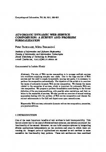
Figure 3 Hypothetical Inter-domain QoS on-demand Service Architecture
3.2 Operational Scenario and Service Extension Figure 3 illustrates the layout of a hypothetical inter-domain QoS on-demand service architecture derived from the ICEBERG Clearing House [5] concept. We attempt to show how dynamic extension of QoS on-demand can be set up from a static confederation of Autonomous Systems. Figure 3 also depicts the DEEPSEA service extension mechanism (shown with the dotted lines) and additional required node entities (shown with the grey node shading). This QoS on-demand service architecture makes the following assumptions: • Each administrative domain have build-in QoS support and it is assumed that once any packets enter an ingress router they will be delivered to the egress router of the domain with the same level of QoS. • There are control entities in the network, referred to as Local Control Point, responsible for intra domain control and Master Control Point, responsible for inter domain control through interaction with Local control Point. The control structure is hierarchical in design.
• The LCP has four major responsibilities, namely, admission control, traffic monitoring, traffic policing and inter-domain traffic aggregation prediction [5]. Three different types of administrative domains are involved. They are the Source/Home Network domain, the intermediate ISP administrative domains and the Sink/Visiting Network domain. All administrative domains are part of the confederation of network domains that provide QoS ondemand. Furthermore, there are the Corresponding Node (CN), and the Communication Host (CH), an entity which request the QoS on-demand session with the CN. Associated with the network resource plane, there is the overlay control plane, the Service Control Plane (SCP), where we assume a hierarchical control structure in this example. In the SCP, the LCP updates the MCP with domain specific high level aggregate traffic statistics. These statistics are gathered through network monitoring, either active or passive, about the administrative domain, by the associated LCP. Interdomain aggregation resource reservations are based on these collected traffic statistics, and advanced resource prediction techniques described in [5] can also be used in assisting the resource reservation process, malicious flow detection and traffic policing.
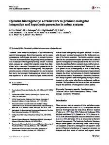
Figure 4 Operation Behavior for Inter-domain QoS Reservation
Figure 4 shows a typical operation behaviour for the inter-domain QoS service creation. Firstly, the local Edge Router (lER) processes individual signalling messages generated by the hosts (e.g. RSVP [15] or H.323 [8] messages) and forward the information to the LCP. The LCP checks the local QoS resource availability and performs admission control. Assuming that admission for intradomain QoS is granted by the LCP, it then consults with the MCP in regarding inter-domain QoS resource availability. From the traffic statistics gathered, MCP is able to determine if the required QoS is achievable inter-domain wise. If so, the MCP performs inter-domain resource reservation with the other Local Control Point (oLCP) in setting up the desired QoS along the communication path. The oLCP(s), in turn, will set up the domain specific resource reservation parameters with associated ERs. This is so that packets are treated similarly QoS wise when flow from one domain to another, as
each domain is likely to have different QoS settings. An ER maps a class of QoS traffic from the other domain to the corresponding QoS level within its domain. As MCP have an end-to-end view of the entire network, it is able to specify the QoS mapping rules to the LCPs which will forward this to its ERs. Upon successful completion of inter-domain resource reservation, the MCP will inform the LCP of the QoS availability. The LCP will subsequently set up the domain specific resource reservation parameters with the lER. Following this, a successful QoS setup confirmation will be send to the CH with the entry point (lER’s address) directing where the CH should send its traffic. Regarding the data path, packets will first be arriving at the ER which the CH begins the initial signalling message with. The ER will then direct these packets to the ingress ER of the transient domain specified by the MCP. Subsequently, the packet stream will be mapped to an equivalent QoS level, as specified by the MCP prior, by the ingress ER. The steam of packets will then be sent across the domain to the egress ER where the packets will be directed to the next transient domain. This process repeats until the packet stream reaches the sink domain where the ingress ER will guide the stream to the specified corresponding end-point. Similar to other service architecture, this hypothetical service model operates on the assumption that there are ‘control’ entities that resides in the network, responsible for managing the services (i.e. creation, monitoring and tear-down). Therefore, in this context, our aim is to dynamically deploy the LCP in the new network where the extensibility is to take place. If we take the example in Figure 2, we can imagine that the deployment of EMod is in fact the deployment of the LCP entity and the ‘CPGJoin’ process is one where the LCP gets to know its network surrounding, as well as the identification/registration of its associated MCP (acts as the Control Point Gateway entity). Then, we can simply replace the ‘SerReq’ and ‘ReqReply’ messaging steps in Figure 2 with the message exchange that take place in Figure 4 starting from ‘QoSReq’ and ends with ‘QoSReply’ message (view CH as EMod). We have just shown the dynamic service extensibility. In essence, the part of the DEEPSEA Framework that performs the registration of new control entities to existing service architecture is a generic process, independent of the underlying service architecture. 3.3 Extension Maintenance, Monitoring and Teardown In DEEPSEA, the Extension Module (EMod) is responsible for session maintenance and/or monitoring. Similar in concept as Active Network’s Active Application [17], EMod can be persistent where it may keep state within the programmable execution environment, or it maybe ephemeral and die after execution. Through SNMP [24] or specialized network device API such as JFWD [17], EMod will be able to execute monitoring and accounting tasks. This will facilitate proper use of ‘hired’ resources as well as determining the appropriate pricing. Moreover, monitoring of the network states (i.e. bandwidth) maybe necessary for certain Active Application, such as our hypothetical QoS on-demand example. It must be stressed that monitoring is passive. We obtain ‘monitoring’ information from the network operator through standardized mechanism, for example, SNMP MIB. We will not be able to actively monitor the actual physical link, as it is enforced by the network operator and the programmable execution environment. In maintaining the service extension, the Extension Gateway (EG) may need to re-negotiate with the Execution Environment Gateway (EEG) if the current resource is insufficient or service extension is not longer required. The teardown process involves the end host application, or the Personal Assistant, (PA) initiating the process. The EG finalizes the extension teardown by decommissioning the associate EMod, together with the settlement of the service extension cost, with the resource providers and the user. We assume that
failure in the EMod or the hardware providing the programmable execution environment will require the service extension to be reconstructed from scratch. There will not be a central entity maintaining the communication state inside the network. 4.0 Implementation In this section, we present an implementation design of the programmable execution environment within the DEEPSEA framework in relation to our QoS on-demand example. However, we will firstly justify why Web switch is our network hardware device of choice. 4.1 Evaluation of Web Switch The thinness of the browser function, which enabled its widespread use, has driven Web servers to take on increased processing burden. The emerging technology in leveraging this problem is the Web Switch, replacing and/or complementing the Web Server Farm and the Web Data Center. In the most basic form, the Web switch is a super-fast LAN switch that integrates the Web traffic management and control functions currently running on separate IP appliances. These include local and global server load balancing, server security protection, traffic steering / redirection and bandwidth management etc. Strategically, the LAN switch represents the ideal platform for such integration. Already providing the common connectivity fabric for all devices in a Web data center while frontending all servers and their applications, this device locates in the best spot for administrators to exert traffic classification and control functions. Essentially, the design of the Web switch includes a wirespeed ASIC-based packet forwarding hardware, servicing normal Layer 2/3 switching, and a programmable software component with the flexibility to perform a variety of Layers 4-7 services. These features match DEEPSEA’s need precisely. The programmability inside the software component of the Web switch will enable the deployment of extensible modules. Together with the good strategic placement for traffic classification and control function feature of the Web switch, we found that it is an ideal solution in enabling the realization of DEEPSEA. With the increasing popularity in Web switches, such as Nortel’s Alteon switching products, we believe that the deployment of the DEEPSEA architecture in real production network is highly probable and achievable in the near future. What we need now is a programmable environment to run our extension services. 4.2 Implementation Design The prototype of the DEEPSEA programmable execution environment was designed using the Oplet Runtime Environment [17] (ORE). The ORE supports dynamically injecting customized software services into network devices. The implemented architecture is composed of an embedded Java Virtual machine (JVM) and the ORE. The ORE component provides the support for secure downloading, installation and safe execution of the extension services on the network devices. Since the ORE and its services are constrained to running in the JVM, system stability of the core network device operation is not affected. Possible ORE services, which run locally on network devices, include monitoring, routing, diagnostic, data transforming and other user specified functions. ORE services can monitor and change specific Management Information Base (MIB) [24] variables locally on the device through the Java MIB API. This direct access to MIB variables on network nodes greatly
improves scalability and reduces network traffic compared with using SNMP manager-agent communication [17]. The ORE architecture consists of the ORE environment, oplets and services. Oplets are selfcontained downloadable units that encapsulate one or more services, service attributes, authentication information, and resource requirements specification. In our context, the EMod will be an Oplet. Oplets can provide services to other oplets. For instance, aggregation of EMod for the QoS ondemand service architecture is possible, if more than one user from the same home network is requesting service extension. The ORE provides means to download oplets, manage the oplet lifecycle, maintain a repository of active services, and track dependencies between oplets and services. The underlying JVM is also modified to perform accounting for both CPU and memory consumption. The ORE services use the Java Forwarding API (JFWD API) [17] to instruct the forwarding engine regarding the handling of packets. The JFWD API is a uniform, platform-independent portal through which application program can control the forwarding engines of heterogeneous network nodes such as switches and routers. Figure 5b shows the ORE implementation in comparison with logical Active Network architecture (Figure 5a). The bottom layer is the System Resource Manager, which provides mechanisms to prevent one execution environment (EE) from interfering with another. These mechanisms include limiting resource to each EE as well as dispatching packets to the correct EE. An EE accepts programs and packets that it deems valid. Active applications (AA) are the actual active custom programs. As can be observed, ORE adhere closely to the Active Networking reference model.
Figure 5 Active Network Reference Model and ORE Model
The network hardware device of choice is the Nortel Alteon 180 Web switch. It achieves web switching flexibility with software programmability and a significantly higher level of performance by introducing two separated working planes ‘control’ and ‘forwarding’. The forwarding plane along the
data path is implemented, at each port, using WebIC network processing ASIC that combines a L2 packet engine with two RISC processors onto a single chip. Up to 10 WebICs are interconnected over an 8Gbps switch backplane. The packet engine in each WebIC switches L2 packets in hardware while the network processors support L3-7 switching in software. In the control plane, with the addition of Alteon’s Virtual Matrix Architecture (VMA), every network processor across all switch ports can process traffic simultaneously regardless of the physical ports through which session traffic traverses. Consequently, VMA creates a virtual matrix of memory and processor resources that can be used to process traffic from any port at any time within the switch.
Figure 6 Prototype design for Programmable Execution Environment
Figure 6 depicts the DEEPSEA programmable execution environment prototype architecture. The control plane utilizes some CPU resources in maintaining the Java Virtual Machine (JVM). Moreover, it runs ORE, and houses diversified network applications that make up the execution environment of customer’s intelligences and value-added services, such as our QoS Extension Module. We name the EMod in our QoS on-demand service architecture, QoSEMod, and it is implemented as an Oplet. ORE and the network extension services are initiated at the control plane. In fact, these services can be divided into two further planes, namely, control and data, according to which plane they serve. Control-plane services deal with network management issues such as altering the forwarding behaviors (e.g. forwarding priority) along the data path. While the data-plane services such as data
transformation cut through the data path and take in and process particular packets before forwarding them. With respect to our extension example, the QoSEMod Oplet performs the four specific required tasks. It monitors the available bandwidth through the Java MIB API and interoperates bandwidth allocation through Alteon’s VMA with the specific WebIC processor at each ingress or egress ports. It predicts future bandwidth allocation requirements using techniques explained in [5]. At the same time, admission and policing control is also carried out via interoperating with the Alteon’s VMA in specifying the behavior of the WebIC accordingly. Linking back to our dynamic VPN example in the Section I, we can see that the dynamicity can be achieved by deploying, on-demand, VPN specific Extension Module that monitors the visiting network similar to that of QoSEMod, while also provides the necessary authentication and security checks at the same time. 4.3 Implementation Limiting Factors Two limiting factors can be identified with our service extension implementation. Firstly, if the extension is requested on a non QoS enabled domain, then service extension will not be achievable as we presume the existence of QoS enabled networks. Secondly, if the extension is requested on a QoS enabled domain, but several administrative domains away from the original service architecture, then chained extension maybe necessary, in order to achieve such service extension. By chained extension we mean a gradual service extension, one-by-one, from the origin administrative domain or autonomous system to the requesting domain. This however, is a specific limiting factor only applicable to inter-domain QoS services provisioning. Normal non-QoS related application service architecture should not encounter such hindrance in service extension. 5.0 Conclusion This paper presented the design of DEEPSEA framework which attempts to broaden the service boundaries of application-level value-added service providers by defining a conceptual method for service extension in a dynamic on-demand and on-the-fly manner. DEEPSEA is unique in that, to our knowledge, it is the first research work exploring dynamic service extensibility for application-level (adaptive) networking service architectures. We have shown our programmable execution environment implementation design for DEEPSEA and illustrated in detail the steps involved in dynamic service extension. In future research, we will explore the implication of DEEPSEA framework on network mobility and the integration of DEEPSEA with Mobile IP. References [1] “Alteon web switching product portfolio website”, http://www.nortelnetworks.com/products/01/alteon/. [2] B. Thai, R. Wan, T. Rakotoarivelo, and A. Seneviratne, “Integrated Personal Mobility Architecture: A Complete Personal Mobility Solution,” Special Issue of MONET Journal on Personal Environment Mobility in MultiProvider and Multi-Segment Networks, 2002. [3] Barbir et. el., “An Architecture for Open Pluggable Edge Services (OPES),” Internet Draft, IETF, May 2002. Work in Progress. [4] C. Wong, HTTP Pocket Reference, O’Reilly, 2000. [5] C.-N. Chuah, “A Scalable Framework for IP-Network Resource Provisioning through Aggregation and Hierarchical Control,” PHD Dissertation, University of California Berkeley, 2001. [6] E. Ray, Learning XML, O’Reilly, 2001.
[7] H. Wang et al., “ICEBERG: An Internet-core Network Architecture for Integrated Communications,” IEEE Personal Communications, August 2000, vol. 7, issue 4, pp. 10-19. [8] “H.323 Standard website”, http://www.itu.int/itudoc/itu-t/rec/h/. [9] J.-C. Chen, et al., “QoS Architecture Based on Differentiated Services for Next Generation Wireless IP Networks,” Internet Draft, IETF, January, 2001. [10] M. Gunter, T. Braun, I. Khalil, “An Architecture for Managing QoS-enabled VPNs over the Internet,” In Proceedings of Local Computer Networks, 1999, pp. 122-131. [11] M. Henning and S. Vinoski, Advanced CORBA Programming with C++, Addison-Wesley, 1999. [12] M. Kirtland, “The Programmable Web: Web Services Provides Building Block for the Microsoft .NET framework,” MSDN Magazine, September 2000. [13] M. Yarvis, P. Reiher, and G. Popek, “Conductor: A Framework for Distributed Adaptation,” UCLA Tech Report: CSD-TR-010025. [14] P. Sookavatana, S. Ardon, and A. Seneviratne, “Discovery Services in Multiple Administrative Domain of Adaptive Network Environment,” In Proceedings of ICT, 2002. [15] R. Braden, L. Zhang, S. Berson, S. Herzog and S. Jamin, “Resource Reservation Protocol (RSVP),” RFC2205, IETF, 1997. [16] R. Isaacs and I. Leslie, “Support for Resource-Assured and Dynamic Virtual Private Networks,” IEEE Journal on Selected Areas in Communications, Vol. 19, No. 3, 2001. [17] R. Jaeger, R. Duncan, F. Travostino, T. Lavian, and J. Hollingsworth, “An Active Network Services Architecture for Routers with Silicon-Based Forwarding Engines,” In Proceedings of LANMAN, 1999. [18] “Sun Open Net Environment – Sun ONE web site,” http://www.sun.com/sunone/. [19] T. Lavian and P.-Y. Wang, “Active Networking On A Programmable Networking Platform,” In Proceedings of OPENARCH, 2001, pp. 95-103. [20] T. Lavian et al., “Enabling Active Flow Manipulation In Silicon-based Network Forwarding Engines,” IEEE Journal of Communications and Networks, March 2001. [21] T. Narten, E. Nordmark, and W. Simpson, “Neighbor Discovery for IP Version 6 (IPv6),” RFC 2461, IETF, December 1998. [22] T.L. Thai, Learning Dcom, O’Reilly, 1999. [23] “The SAHARA project website”, http://sahara.cs. berkeley.edu/. [24] W. Stallings, SNMP, SNMPv2, SNMPv3, and RMON 1 and 2, Addison-Wesley, 1999.