Dynamic Skinning : Adding Real-Time Dynamic Effects to an Existing Character Animation Caroline Larboulette∗ GRAVIR & SIAMES-IRISA – currently TU Wien
Marie-Paule Cani† GRAVIR
Bruno Arnaldi‡ SIAMES-IRISA
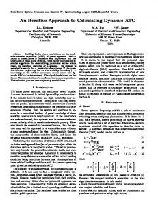
Figure 1: Animation of a cat model, in real-time, using our dynamic skinning with one flesh element in the belly region. The (blue) dashes represent the displacement field of the skin vertices between their smooth skinning position and their dynamic skinning position.
Abstract This paper proposes a simple and efficient technique to enhance classical animations of characters by adding a dynamic response of the skin to the movement of the underlying skeleton. The dynamic effects are locally added to the shape obtained through the standard skinning by specifying flesh elements. Our solution relies on a new second skinning operation that blends the current flesh volume computed through smooth skinning with its position in a dynamic frame attached to the skeleton through a visco-elastic element which, combined with a set of weights, controls the local behavior of tissues. We show how the weights can be automatically computed, taking into account the morphology of the limb. The resulting real-time technique is well suited to video games or any application where we need to add dynamic effects, at almost no cost, to an existing animation sequence.
it is attached to and about smooth skinning when the position of a vertex is a weighted sum of its rigid positions related to several different joints. When the skeleton is animated, either by forward kinematics, inverse kinematics or motion capture, it drags the skin vertices. Unfortunately, these animations suffer a major drawback. Binding the skin to the skeleton prevents the appearance of any dynamic effects due to the inertia of tissues. However, these effects are essential to make any animation involving sharp movements like running or jumping believable. Despite these drawbacks, the skinning technique has several advantages: the new positions of vertices are computed in real-time, the kinematic deformations can be well modeled if using the solutions presented in [Kry et al. 2002; Bloomenthal 2002; Wang and Phillips 2002; Mohr and Gleicher 2003], and it’s a technique widely used among computer artists. Our goal is thus to add dynamics to an existing animation, without modifying its kinematic deformations or any post-processes, while keeping the whole technique real-time.
CR Categories: I.3.7 [Computer Graphics]: Three-Dimensional Graphics and Realism—Animation Keywords: real-time, skinning, dynamics
1
Introduction
In the 3D animation movies and video games industries, the deformation of a character’s skin is generally computed through skinning. To set up an animation, the artist first designs the character’s shape (a skin), which is a surface polygonal mesh. Later on, he/she builds a skeleton1 and binds the surface skin to its joints. Then, during animation, the current positions of vertices are computed from the positions of the skeleton frames. This process is called skinning. We talk about rigid skinning when a vertex rigidly follows the joint ∗ e-mail:
[email protected] [email protected] ‡ e-mail:
[email protected] † e-mail:
1 In this context, a skeleton is a hierarchy of frames that is used to describe the movement of a character. The shapes of the bones are not modeled.
The simple method we propose in this paper does not require any modification to the original polygonal mesh, skeleton or animation. To be usable in real-time in video-games and to be compatible with industrial standards, we rely on a standard skinning technique rather than on a full physically based simulation of tissues. Our method is used to generate dynamic deformations initiated by the skeleton motion in all regions where such effects are desirable, typically, a volume of flesh between two skeleton joints. Since we rather aim at visual plausibility than accuracy, our tool mimics the overall visual effect a physically based simulation would provide. In particular, the direction, frequency, and amplitude of flesh deformations remain plausible and no noticeable change in the volume of tissues is generated. Our solution relies on a new second skinning operation that blends the current flesh volume computed through smooth skinning with its position in a dynamic frame attached to the skeleton through a visco-elastic element. This frame reflects the dynamics of motion, so we refer to this process as dynamic skinning.
The remainder of the paper is organized as follow. Section 2 reviews related work. Section 3 clarifies our goals and presents the principle of our approach. Then section 4 details the construction of a flesh element and its associated local and dynamic frames used for the dynamic skinning. Section 5 describes our automatic computation of dynamic skinning weights and a geometric constraint on the frames relative positions. Section 6 presents our results and discusses the benefits and limitations of our approach with respect to previous methods. The last section concludes and lists future work.
2
Related work
Previous work either addresses the problem of automatically computing good frames and weights to improve smooth skinning [Kry et al. 2002; Bloomenthal 2002; Wang and Phillips 2002; Mohr and Gleicher 2003] or studies anatomical or physically based deformable models, having little concern for their usability for designers. This section describes the techniques that provide dynamic effects to muscles and/or fatty tissues and discusses their usability for enhancing an existing animation in real-time. The first attempt to add dynamic effects to the skin of articulated characters was that of Chadwick [Chadwick et al. 1989]. In his technique based on free form deformations, he replaces the control points of the FFD lattice by masses linked by springs. Some of the mass points are attached to the skeleton frames so that their rigid motion induces forces between the springs. The 3D lattice thus deforms when the skeleton moves, yielding a dynamic deformation of the embedded polygonal mesh. This technique was used to animate the cheeks of a character. Several similar techniques have been explored since then. Turner [Turner and Thalmann 1993] uses an elastic surface to represent a deformable skin layer. This surface is attached to the underlying components through a repulsive fat layer of constant thickness and attractive springs anchored to the muscles. Wilhelms [Wilhelms 1997; Wilhelms and Gelder 1997] uses a similar approach but with a polygonal elastic surface composed of masses (vertices) and springs (edges) which is directly attached to the underlying structures (either muscles or bones) through a set of springs. That allows the surface to slide and stretch according to the deformation of the underlying structures. These anatomically based techniques however require a lot of input from the user for a very precise result while we aim at providing a minimalist and easy to set up model. More accurate physically based models based on elasticity theory were also used to animate a dynamic skin controlled by a skeleton. Capell [Capell et al. 2002] animates the deformable tissues of a model by embedding it into a volumetric finite element lattice on which a hierarchical basis is defined, so that the level of detail can be locally adapted. The deformation of the lattice is computed from the movement of the skeleton, which can be defined using some edges of the lattice. The animation of a single, geometrically complex model is achieved at interactive rates using a coarse lattice and a simple skeleton. M¨uller [M¨uller et al. 2002] reaches realtime performances for large deformations by using a pre-computed linear stiffness matrix to compute the deformations, which is made possible by extracting the rotational part of the transformation of vertices and adding it back after integration. James [James and Pai 2002] pre-computes the vibration modes of a local finite element mesh and combines them in real-time thanks to a hardware implementation of modal analysis [Pentland and Williams 1989]. While this technique gives good results (visually and physically correct), it requires the animator to have good physics skills to set up the finite element simulation. This technique also requires him to provide a volumetric mesh for the model, while he only has a surface model. We do not want to ask so much input from the user, especially when dealing with skills he does not have. The physically based approaches offer a guaranteed realism for the animation of elastic tissues. However, getting the right elasticity parameters for the anisotropic, constant volume organic tissues composing a body is not easy. If manually tuned parameter values are to be used it may be more convenient to use a method that only provides plausible results, but that is easy to implement, easy to use and provides intuitive parameters to an artist. The technique we present in this paper chooses this approach.
3
Principle of our dynamic skinning
3.1
Goals
Before describing our model, we first propose a list of constraints on the shape and location of the skin deformations we want to obtain. Our first observation is that the amplitude and frequency of vibrations are local and on a per limb basis. Let’s first approximate the deformation of a fleshed bone in the real world by the deformation of a simple model. A regular limb (e.g. a thigh), is composed of a rigid bone surrounded by a visco-elastic volume made of flesh and fatty tissues. This material is obviously not homogeneous, but, for a rough approximation we often see in previous work, we will assume it is. Our theoretical model for such a regular limb is a rigid cylinder (the bone), surrounded by a deformable cylinder (the flesh and fatty tissues). As we do not want deformations around the joints, we also assume that the top and bottom of the cylinder are rigid. Figure 2 shows the deformations we would obtain for such a model, under two different accelerations of the bone. This observation makes us infer 3 requirements. 1. The dynamic deformations increase with the muscles and fatty tissues thickness around the bone. 2. As the joints should be able to articulate while maintaining the continuity of the skin at the borders of the region covered by the flesh element, the deformation should be complete near the center of the bone, and null near the joints. 3. Whatever the skeleton’s motion, the flesh should not be pushed or pulled to the other side of the bone. Joint (rigid) Bone (rigid)
P1
Muscles Fatty tissues (visco-elastic)
P2 Bone Acceleration
P1 P1
P2
Bone Acceleration
P2
Figure 2: A mechanical model of a regular limb and its deformations under two different accelerations.
3.2
Principle of the technique
At each animation step, skin vertices are first deformed through a standard smooth skinning process, from the position of the skeleton frames. A second skinning layer (the dynamic skinning) is then applied in regions covered by the flesh elements. It blends the current position of each vertex in the local frame of the flesh element with its position in the dynamic frame attached to it. This process propagates the dynamic effect modeled by the flesh element to the character’s skin. As in any skinning process, choosing adequate weight values for blending vertex positions in different frames is crucial. This automatic computation will be detailed in section 5 while next section
details the specification of a flesh element and the behavior of its associated spring.
4
Flesh element
In the remainder of this paper, we use the term flesh element for the volume of flesh that surrounds a portion of the model’s skeleton whose points vibrate and deform in a synchronous fashion. For instance, each portion of a character limb between two consecutive joints will be associated with a different flesh element. In contrast, the character’s body at the stomach level will be modeled using a single flesh element although it is defined by more than two joints. A possible configuration of flesh elements covering an entire articulated character are depicted in figure 3.
Moreover, as the spring is only anchored to the local frame through a single point, it is free to rotate around the local frame. The punctual mass positioned at the origin of the dynamic frame represents the mass of the flesh element. The direction and amplitude of the spring elongation thus models the inertia of the flesh. Organic tissues being of constant density, the mass value can be computed from the volume of the flesh element, unless the user wants to tune it differently. The spring rest length is set to zero. Being at the same location, the local and dynamic frames will thus generate no deformation from the standard skinning process at the initial position. The user tunes the damping ratio and the stiffness of the spring according to the range of deformations and the frequency of vibrations he desires. Driver Frame
Driver frame
P Fd
Fs
Driven Frame
Root
Driven frame
(b)
P
Local Frame
Fd
Skeleton frame
Skeleton Frame Flesh Element
Fs
Father Son Hierarchy
Fd
Fs
(a) Driver frame
P
Virtual Bone
Flesh element
Damped Spring
Children frames
(c) Figure 3: An articulated character, an example of its decomposition into flesh elements and their corresponding local frames.
4.1
Specification of a flesh element
The user specifies a flesh element by selecting a set of vertices, a skeleton frame and a subset of its descendants in the hierarchy. A virtual bone is then defined as the line segment joining the parent frame, which we call the driver frame, and the barycenter of the selected frame(s) at a lower level in the hierarchy, which defines the driven frame (see figures 3 and 4). The local frame of the element is positioned at the middle of the virtual bone and its y-axis is aligned with the virtual bone. This frame rigidly follows the driver frame during the animation. The deformation of the flesh element will thus be defined from the local frame’s motion such that the deformation smoothly vanishes at the borders with neighboring flesh regions.
Figure 4: A dynamic frame Fd is connected to a local frame Fs through a damped spring of zero rest length. (a) and (b) : the local frame stands in the middle of the virtual bone delimited by two end joints. (c) : the local frame is defined by three end joints. As will be detailed in Section 5, the damped spring needs to be constrained to a maximal elongation value so that the flesh element still surrounds the virtual bone whatever the sharpness of motion. When the elongation of the spring exceeds the maximum authorized value, we simply correct the position of the dynamic frame by setting the elongation back to the maximal value, without modifying the current speed of the punctual mass. In addition to the spring force, we are currently taking into account a pseudo-gravity force in our animations. The user can tune this force to obtain different static shapes and dynamic deformations of the skin. Other forces, such as an air friction force would be easy to add.
4.3 4.2
Simple mathematical expression
Dynamic frame
In addition to its local frame tied to the skeleton, a dynamic frame is associated to a flesh element, which aims at capturing the viscoelastic vibrations of the muscles and fatty tissues when the skeleton moves. We use a damped spring – which is the minimal model for a visco-elastic element – to model the attachment between the dynamic and the local frames (see figure 4). In our current implementation, the relative orientations of the local and the dynamic frames are not taken into account in the computation of the deformations.
Let P denote the final position of a chosen vertex. If we call P1 , the position of this vertex in the local frame after smooth skinning, P2 the same position of this vertex in the dynamic frame, when expressed in the local frame, P will be computed as: P = α1 P1 + α2 P2
(1)
where α1 and α2 are the skinning weights we need to define. As in regular skinning, we set the constraint α1 + α2 = 1 to keep the
deformation within the convex hull of the positions defined by the two frames.
~t ~t ~t which results in :
= = =
~t = α2~u
(2)
Automatic computation of the skinning weights
First approximation
shape(x, z) = d(P1 , B)
(3)
where P1 is the vertex position in the local frame after the first pass of standard smooth skinning, B is the line segment representing the bone, and d is the Euclidean distance. See figure 5 (a). A bone thickness can be taken into account in the computing of shape(x, z). It’s only an offset, that is some scalar we need to remove from the distance computed in equation 3.
Attenuation
The second mathematical function, which we call attenuation(y) relies on the shape of the deformation and corresponds to an attenuation of the deformation near the extremities of the bone. We need
Fs
0
x 1
P2 -1
(a)
The first constraint which describes the fact that vertices which are far from the bone should move more than the others is directly related to the morphology of a limb (thickness of the flesh and fatty tissues around the bone). Let’s call shape(x, z) the function that expresses the dependence of the weight value α2 from the skin vertex position in the (x, z) plane. According to equation 2, the further from the bone a vertex is, the larger α2 should be. To be able to tackle the third constraint (the skin cannot cross the bone) using a single maximal elongation threshold, shape(x, z) should be a linear function. We thus set the amplitude of deformation as being directly proportional to the distance of the vertex from the bone :
5.2
x z
d2
The weights are automatically computed to take into account the constraints detailed in section 3. The two first constraints are maintained through two mathematical functions, which are combined for computing the weight value α2 at each skin vertex. These function values are computed in the local frame of the flesh element (see figure 5) using the following convention : the origin lays in the middle of the virtual bone associated with the flesh element (i.e. origin of the local frame); the y-axis is aligned with the bone; while the x and z-axis go in the perpendicular directions.
5.1
y
Fs
y
(α1 − 1)P1 + α2 P2 −α2 P1 + α2 P2 α2 P1~P2
The final shape thus only depends on the weight α2 at each skin vertex and the spring elongation and direction, expressed by the vector ~u. The challenge is now to automatically compute the weights α2 in order to correctly reflect the dynamic effects provided by the damped spring through skin deformations.
5
d1
P1
Let first note that we can express the deformation described by equation 1 directly relative to the spring elongation ~u : let ~t be the translation we need to apply to P1 to obtain the final P: ~t = P − P1 . Equation 1 yields:
1
(b)
Figure 5: (a) : the weight given by the first constraint corresponds to the Euclidean distance between the vertex and the flesh element virtual bone. It corresponds to d1 for P1 and to d2 for P2 . (b) : the attenuation function that attenuates the weights given by (a).
to ensure that the dynamic skinning process does not deform the skin at joints, so that no discontinuity is generated at the border of a flesh element. Meanwhile, the flesh deformation at the center of the bone should reflect the movement of the dynamic frame. These constraints can be expressed as: attenuation(y) = 0 for y = −1, attenuation(y) = 1 for y = 0, attenuation(y) = 0 for y = 1. The simplest function satisfying these constraints is a parabola : attenuation(y) = 1 − y2 . However, this function doesn’t decrease with a zero tangent in −1 and 1 so it may degrade the smoothness of the skin. We thus also provide bell shapes functions in our framework, such as Wyvill’s polynomial function [Wyvill et al. 6 4 −22∗y . Any other function 1986]: attenuation(y) = 1 + −4∗y +17∗y 9 that fulfills the constraints may be used instead. For example, we could imagine an appropriate interface where the user could define his/her own function by playing with tangents and amplitudes of Hermite splines in order to control the global shape of the deformation. The final weight α2 is a combination of shape(x, z) and attenuation(y):
α2 (x, y, z) =
shape(x, z) ∗ attenuation(y) max(shape ∗ attenuation)
(4)
where max(shape ∗ attenuation) is the maximal value reached anywhere on the flesh element. This normalization is compulsory since it ensures that the weights remain between 0 and 1. The curve obtained for the weights is shown for an example of irregular limb and two different attenuation functions on figure 6. Note that α2 weights are computed only once, during the character set up. 1.5
1.5 1
0
0
0 -1
1
(a)
-1
1
(b)
-1
1
(c)
Figure 6: (a) One example of shape(x). (b) Parabola attenuation function (plain line) and Wyvill attenuation function (dashed line). (c) Resulting weights before normalization, for each attenuation function presented. Note the non zero tangent of the weights curve obtained with the use of the parabola (plain).
5.3
Maximal spring elongation
During animation, the final position of a vertex p (see equation 2) is given by α2 (p) ∗~u. In order to prevent a vertex from crossing a bone, we allow it a maximum displacement which depends on its distance from the bone and its weight α2 . This can be done simultaneously for all vertices by constraining the spring to a maximal elongation value equal to the maximal weight value for the limb (α2 -max) before normalization. Going back to graphs (figure 6), the linearity of the shape function (in (a)) prevents the weight curve from crossing the shape curve, which actually ensures that no vertex can cross the bone during motion.
6
We performed the physically based simulation by first precomputing a 3D mesh of tetrahedra from the surface mesh. We then associated masses to vertices and damped-springs to the edges of each 3D tetrahedron. We finally rigidly attached the vertices lying in a small cylinder around the skeleton segment to the skeleton’s frame, in order to model a rigid bone inside the mushroom volume. Results from the two simulations are depicted in figure 8. While our method is several orders of magnitude faster (one independent spring instead of a network of 3000 interconnected springs), there is no visual difference in terms of the plausibility of the deformation.
Results and Discussion
Due to the simplicity of our method, the extra skinning layer is computed at almost no cost. This makes the method eligible for video-game applications, even when a whole population of characters needs to be animated. The analysis of the results thus rather addresses the visual quality of deformations we obtain and the quality of control the user has rather than the high performance of the method. As evaluating dynamics on still images is difficult, we’ve added (blue) displacement vectors on each image, which describe the vertices displacements between the smooth skinning and the dynamic skinning shapes. The corresponding video sequences can be found at http://www-evasion.imag.fr/Publications/2005/LCA05/.
6.1
Validation on a simple case
We validated our real-time method by qualitatively comparing the resulting deformations with those that result from a full physically based simulation of a volumetric flesh element. The comparison was done using a single flesh element along a vertical skeleton segment (see figure 7). We gave a mushroom shape to this element in order to get large thickness variations along the skeleton.
Figure 8: Comparison between a physically based simulation and our dynamic skinning onto the same model driven by a similar motion of its rigid skeleton. Top row : the 3D mass-spring model made of about 3000 damped springs. Bottom row : same model animated with our dynamic skinning using one flesh element.
6.2
Simulation of physical parameters
Even if our model is very simple, it remains a physical model to which one can add forces like gravity or air damping. Figure 9 shows our mushroom model at rest undergoing different gravity forces.
g = 16.3 N.Kg−1
g = 36.4 N.Kg−1
g = 63.4 N.Kg−1
Figure 9: Our mushroom model is simulated under various gravity forces: under high gravity, the model is more deformed.
6.3
Animation of complex characters
The cat model of figure 10, composed of 1296 vertices has been animated with one flesh element in the belly region (of about 500 vertices) performing a simple running motion (see figure 1). Figure 11 shows the same model with the same parameters, but in a different kind of movement (a jumping instead of a running motion). Only the keyframe animation of the skeleton has been replaced. Figure 7: A surface mushroom model deformed by our dynamic skinning method using a single damped spring.
Our second model, composed of 5554 vertices, has been animated using 4 flesh elements : one for breast, one for each arm, and one for the belly and bottom regions. The first row of figure 12 shows
Figure 10: Left: the dynamic skinning weights of the cat model which vary from 0 (black) to 1 (white). Right: the damped spring of the flesh element (the left square stands for the local frame origin and the right square for the dynamic frame origin).
Figure 12: The breast, arms, belly and bottom of this Eva model have been animated in real-time using 4 connected flesh elements. The first image shows the dynamic skinning weights values at rest and the second image shows the positions of the local frames.
Figure 11: The same cat model deformed using the same flesh element parameters in the belly region in a jumping motion.
the positions of the springs and the associated weights while the bottom row shows some snapshots from the animation.
6.4
Combination with other tools
In order to show that our dynamic skinning acts like an extra layer, without modifying underlying or surrounding layers, we have applied our technique to a classical skinning enhanced with the wrinkles generation tool presented in [Larboulette and Cani 2004]. Used to generate either skin or garment folds under an underlying skin deformation, this method is a good way to enhance the visual complexity of our animations while remaining in a real-time framework. The first layer is thus the standard skinning animation, the second layer our dynamic skinning and the third layer, the wrinkles generation tool. The animation obtained is depicted in figure 13. Our algorithm can thus be plugged in any animation system, as an intermediate layer that adds dynamics to the animation.
6.5
Discussion of our method versus previous ones
The main benefit of our dynamic skinning method over most previous techniques lies in its performance : on the cat example, we are using 1 spring where Wilhelms [Wilhelms and Gelder 1997] would use about 6000. In comparison with the effective GPUbased method of James and Pai [James and Pai 2002] based on pre-computed vibration modes for volumetric representations of the flesh elements, our method does not require any heavy precomputation. While gaining time during the pre-computation step is not a great improvement, not requiring a volumetric description of the model is. Moreover, specifying a set of physical parameters like masses at nodes, stiffness and damping coefficients for a finite element simulation is not straightforward for someone not familiar
Figure 13: Our dynamic skinning has been applied to a cat animation enhanced with a wrinkles generation tool that runs on top of it as a third layer.
with physics. In comparison, our simplified model requires only one mass parameter, one stiffness coefficient and one damping coefficient, which are tunable in real-time during the animation to get the desired result. Another advantage of our method is its ease of implementation as we rely on the widely used standard skinning technique rather than on intricate physically based simulations and that is real-time without the need of specific hardware acceleration. Lastly, the simplicity of user input, in particular in comparison with anatomical models where the geometric shapes of the skeleton bones and muscles need to be modeled, makes our technique directly usable by artists. This simplicity moreover enables to re-use any existing animation of a skinned character with very little extra user effort. Of course, this technique is not as realistic as anatomically based models or as closed to exact physics as finite element simulations can achieve. However, in a real-time context (e.g. video games), as the deformations are instantaneous and our brain cannot exactly analyze the different images, the frequency and general shape of vibrations are more important than the exact shape of the deformation. Our results show that, in many cases, the deformations we obtain conform to expected ones.
7
Conclusion and future work
This work has shown that dynamic effects can easily be added, at almost no cost, to an existing animation of a skinned character. Our technique is based on a second skinning layer that works on top of the standard smooth skinning process, and for which the skinning weights are automatically computed. A single spring per flesh element is used to capture the direction, amplitude and frequency of flesh deformations when the skeleton moves. This makes the method easy to implement and to tune. Of course, this paper only addresses the problem of adding dynamic effects to a skinned character without trying to correct the flaws of classical skinning such as the flatness near a joint when it bends too much, or the thinning of the mesh when the local frames it depends on are twisted relative to each other. We also did not try to model kinematic muscle deformations like bulging which are more important in slow kinematic movements than in dynamic ones. To avoid these drawbacks, one of the solutions proposed in [Kry et al. 2002; Bloomenthal 2002; Wang and Phillips 2002; Mohr and Gleicher 2003] could be integrated in our framework. Our work could be extended in several different ways. First our spring is free to rotate around its anchor point, but it cannot rotate around its own axis. We could thus add a torsion couple or use three springs instead of one to orient the dynamic frame relative to the local frame. Another way to improve the possible deformations would be to anchor additional springs to the local frame with different stiffness and damping coefficients, that would vibrate at different frequencies and compose their movements like in modal analysis. More long term focuses would be to add a collision detection and response algorithm to our model in order to avoid flesh interpenetrations and a volume conservation constraint to create more realistic deformations. Acknowledgements The authors would like to thank Christine Depraz, infographist, for setting up most of the animations presented in this paper.
References B LOOMENTHAL , J. 2002. Medial-based vertex deformation. In Proceedings of the ACM SIGGRAPH Symposium on Computer Animation, ACM Press, 147–151. C APELL , S., G REEN , S., C URLESS , B., D UCHAMP, T., AND P OPOVIC , Z. 2002. Interactive skeleton-driven dynamic deformations. In Proceedings of SIGGRAPH’02, ACM Transactions on Graphics, vol. 21, 586–593. C HADWICK , J. E., H AUMANN , D. R., AND PARENT, R. E. 1989. Layered construction for deformable animated characters. In Proceedings of SIGGRAPH’89, ACM Computer Graphics, ACM Press, vol. 23, 243–252. JAMES , D. L., AND PAI , D. K. 2002. Dyrt: Dynamic response textures for real time deformation simulation with graphics hardware. In Proceedings of SIGGRAPH’02, ACM Transactions on Graphics, vol. 21, 582–585. K RY, P. G., JAMES , D. L., AND PAI , D. K. 2002. Eigenskin: real time large deformation character skinning in hardware. In Proceedings of the ACM SIGGRAPH Symposium on Computer animation, ACM Press, 153–159.
L ARBOULETTE , C., AND C ANI , M.-P. 2004. Real-time dynamic wrinkles. In Proceedings of Computer Graphics International’04, IEEE Computer Society Press, 522–525. M OHR , A., AND G LEICHER , M. 2003. Building efficient, accurate character skins from examples. In Proceedings of SIGGRAPH’03, ACM Transactions on Graphics, ACM Press, vol. 22, 562–568. ¨ M ULLER , M., D ORSEY, J., M C M ILLAN , L., JAGNOW, R., AND C UTLER , B. 2002. Stable real-time deformations. In Proceedings of the ACM SIGGRAPH symposium on Computer animation, ACM Press, 49–54. P ENTLAND , A., AND W ILLIAMS , J. 1989. Good vibrations: Modal dynamics for graphics and animation. In Proceedings of SIGGRAPH’89, ACM Computer Graphics, ACM Press, vol. 23, 207–214. T URNER , R., AND T HALMANN , D. 1993. The elastic surface layer model for animated character construction. Proceedings of Computer Graphics International’93, 399–412. WANG , X. C., AND P HILLIPS , C. 2002. Multi-weight enveloping: least-squares approximation techniques for skin animation. In Proceedings of the ACM SIGGRAPH symposium on Computer animation, ACM Press, 129–138. W ILHELMS , J., AND G ELDER , A. V. 1997. Anatomically based modeling. In Proceedings of SIGGRAPH’97, ACM Computer graphics, ACM Press/Addison-Wesley Publishing Co., 173–180. W ILHELMS , J. 1997. Animals with anatomy. IEEE Computer Graphics and Applications 17, 3 (May), 22–30. W YVILL , G., M C P HEETERS , C., AND W YVILL , B. 1986. Data structure for soft objects. The Visual Computer 2, 4 (Aug.), 227– 234.