Dynamic teams of networked vehicle systems J. Borges de Sousa
Anouck R. Girard
Dept. de Engenharia Electrot´ecnica e Computadores Faculdade de Engenharia da Universidade do Porto R. Dr. Roberto Frias, 4200-465 Porto, Portugal Email:
[email protected]
Dept. of Mechanical Engineering at Columbia University New York, NY 10027, USA E-mail:
[email protected]
Abstract— The design of a distributed control framework for dynamic teams of unmanned vehicles is discussed. The problem is formulated for a border patrol scenario. In this scenario there is a region under surveillance, a set of vehicles with different capabilities and the ability to provide elemental services which can be combined to provide composed services, and human operators. The problem consists of designing a distributed control structure which is able to match the capabilities of the system to the surveillance requirements with the help of mixed initiative interactions (human operators in the feedback loops). The distributed control framework consists of a hierarchy of team and sub-team controllers, vehicle supervisors, and elemental maneuver feedback controllers. The control framework is described as a dynamic network of hybrid automata. The problem of resource allocation is formulated as a problem of team formation.
I. I NTRODUCTION A large body of research has been published in recent years about motion control of Unmanned Aerial Vehicles (UAVs). An increasingly large number of hardware platforms [1], [2], [3], [4], [5] are available for those wishing to validate their ideas experimentally. At this point, much of the work available in the literature [6], [3] deals with motion control of vehicles, usually in the form of waypoint following or trajectory tracking. Parallel advances in wireless communication technologies are enabling applications that include cooperative control of multiple UAVs working together to accomplish a greater mission goal. Multiple-UAV control strategies are emerging, for example in battlefield scenarios where N UAVs are assigned to strike T known targets in the presence of dynamic threats [7], [8] and in the fields of synchronized path planning and cooperative rendezvous problems where multiple UAVs must arrive at their targets simultaneously [9], [7], [10], [11], [12]. Cooperative strategies have also been considered, for example in [13], which considers cooperative search strategies under collision avoidance and communication range constraints, and in [14], which presents a completely decentralized, hybrid systems approach and does not require that the UAVs stay within communication range of each other, as well as in [15], [16] which consider formation flight problems. Other approaches to supervision and control of multiple UAVs are considered in [15], [17]. In this paper, we present an approach for the coordinated operation of dynamic teams of networked vehicles. To motivate our developments consider the following surveillance
problem which arises, for example, in border patrol applications. The area under surveillance is large, diverse in terms of topography and vegetation, with few roads, and has several micro-climates. The objects of interest for surveillance are pedestrians and cars. The surveillance assets include cars, unmanned air vehicles and sensor networks. Each asset has specific sensing attributes which include range, resolution, and sensitivity to weather conditions. The specifications for a surveillance system include a 24h presence with routine assignments, adaptation to time-critical detections and weather conditions, and mixed initiative interactions. This means that the performance of the system should not be affected by the refuelling and servicing schedules for the UAVs. The performance of the surveillance system is measured in terms of how well it matches the surveillance requirements which change due to the weather conditions, and to the detected activities of the objects under surveillance. The problem of designing a controller structure for the surveillance system is not a trivial task. First, the design specifications are expressed in terms of surveillance parameters which are not related to the usual notions of motion control, such as trajectories and way-points. Second, the surveillance system is composed of assets which come and go while the system must retain its properties. Third, the surveillance system must adapt its structure to time-varying requests. Fourth, the system should facilitate mixed initiative interactions to account for the supervision of specialized human operators. To address this design problem we need to consider adequate abstractions of vehicle behavior, to model the structure of the system and the way it evolves under controlled conditions, and to be able to express the state of the system and the control specifications in a way that make it feasible for mixed initiative interactions in real-time. The paper is organized as follows. In section II we introduce an illustrating example to motivate our developments. In section III we discuss how to model the surveillance requirements and the surveillance assets. In section IV we formulate the design problem. In section V we discuss our approach to solve this problem. In section VI we illustrate some aspects of the approach with simulation results. In section VII we draw the conclusions and discuss future work.
II. M OTIVATION To motivate our developments we consider a border patrol scenario. In this scenario a fleet of UAVs and ground vehicles is assigned to patrol a stretch of border; the ground vehicles can be dispatched to investigate slow moving objects of interest. By border we mean a geographical region, with a general assumption that the region will be somewhat long and thin. The approach can be applied to geographical borders as well as to area perimeters, etc. The border is split into sectors (a portion of a military front or area of operation), that are sub-regions of the border area that are roughly of the same size and shape. Sectors are then assigned to the aircraft as part of their patrol route. These subdivisions can be computed off-line, and are downloaded onto each aircraft prior to the mission. We assume that some type of supervisory controller is located in a central location, and that a human operator may be called in to examine video feed and decide whether a specific target is worth tracking. That is, this approach is based on mixed initiative interactions. For example when an aircraft’s resources, such as fuel, get depleted, the aircraft alerts the supervisor and returns to base. The sectors are reconfigured and redistributed to the remaining aircraft to maintain continuous coverage of the border. The aircraft are equipped with cameras and onboard image processing capabilities. If the aircraft detects that it has acquired a potential target, it starts following that target (if the target is stationary, the aircraft will have to circle the target). It also radios back to the central station, alerts the operator, and sends a video image. If the operator decides that the target is worth tracking, the aircraft is assigned to follow it. The sectors that the aircraft was patrolling are dynamically reassigned to neighboring aircraft. Consider now the following use case. Three aircraft (A, B and C) are assigned to patrol the border which is partitioned into three sectors. Each aircraft patrols one sector. At some point, aircraft B detects a suspect vehicle, or target. It uses a target tracking algorithm to stay within range and keep the vehicle in its field of vision, and radios back to the operator. The operator confirms the target, and aircraft B starts following the target. Aircraft A and C get notified of their new assignments: aircraft A and C’s sectors are modified to provide continuous coverage of the border. If the operator never confirms the target, after a set period of time aircraft B returns to patrolling its original sector and the assignments do not change. III. M ODELS In order to formulate the design problem we need to consider models of the region under surveillance, of objects of interest for surveillance, and of surveillance assets. We describe these models next. There are o = 1, . . . , O types of objects of interest for surveillance. These include as cars, trucks, and pedestrians. The region under surveillance is modelled as a graph G = (N , E). The set of nodes is N := {np : p = 1, ...P } and the set of arcs is E. The nodes represent sub-regions. To each node
we associate a vector of sub-region attributes; these include area and type of terrain. The arcs are labelled with a vector of geographic attributes, such as distance between two nodes. It may happen that two adjacent nodes are not linked by a road; in this case there is no arc connecting them. Here, we are not concerned with how this graph is constructed. Criteria for constructing this graph could include area weighted by weather or terrain factors, locations of sensor networks, etc. To model the evolution of the region under surveillance we associate to each node in G a state vector v(np )(t), p = 1, . . . , P which describes the state of the corresponding subregion at time t. The state information includes a description of weather and terrain conditions which might affect the performance of some sensors, as well as a description of the objects of interest. The state of the region is not fully accessible and we need estimates vb(np )(t) of the state at each sub-region at time t. This is why we need the surveillance system, and also information concerning weather and terrain conditions. There a = 1, . . . , A types of surveillance assets, which include UAVs and ground vehicles. We use the notion of service to abstract the surveillance capabilities of each asset. The notions of elemental service, service composition and service network are particularly useful to model our problem domain [18]. Each type of surveillance asset provides a set of elemental services, in particular elemental surveillance services. Thermal and video imaging are examples of elemental services. Elemental services are composed to to build composed services that could not be delivered otherwise. This composition can take place over a network. This means that different assets may contribute elemental services to jointly deliver a composed service. An example of a complex service is a Ground Moving Target Indicator (GMTI). This service requires the composition of several elemental services: thermal and video imaging services provided by a UAV; computational services provided by a ground vehicle; and elemental communication services provided both by the ground vehicle and by the UAV. Another example consists of the remote imaging service: an UAV provides an elemental video imaging service to a ground vehicle to pursue an object of interest, even when it cannot detect it; to do this both vehicles have an elemental communication service and are within communication range of each other. Service composition is done incrementally, starting with what is required in terms of elemental services, then proceeding to model elemental services as part of a service network. There are rules of composition and invariants for service delivery. The rules of composition prescribe how to compose elemental services. The invariants for service delivery prescribe the conditions under which the service can be delivered. The GMTI service can be delivered when an UAV and a ground vehicle providing respectively the thermal and video imaging elemental services are within communication range of each other. The service network has to be controlled so that the invariants required for service delivery become invariants for the operation of the system [8].
There are s = 1, . . . , S elemental services. The elemental services provided by an asset of type a is given by a 1 × S matrix bss: the i − th entry is 1 if it provides the elemental service of type i and 0 otherwise. There are c = 1, . . . , C types of composed services. The rules of composition are given by a C × S matrix CR and by a configuration type ct = 1, . . . , C. The (i, j) entry of CR is 1 if the elemental service type j contributes to the composed service of type i; it is 0 otherwise. The configuration type j is a predicate on the surveillance assets which describes the invariant for the delivery of the composed service of type j. For example, the remote imaging service requires an UAV and a ground vehicle to satisfy communication constrains (state constraints) in addition to being able to provide the elemental services required for the delivery of this service. The surveillance assets allocated to each sub-region at time tk , k = 1, ldots, K are represented by a vector sa(np )(tk ) where the a − th entry is the number of assets of type a present in that sub-region. IV. P ROBLEM The problem consists of designing a surveillance system which, given an estimate of objects of interest vb(np )(tk ), k = 1, ldots, K produces an allocation of assets sa(np )(tk ) to each node of the region graph G, organizes them as teams and subteams, and coordinates and controls them under mixed initiative interactions to maximize the surveillance performance. These are several aspects to this problem. Allocation: to design the allocation procedure. Structure: to design a structure of controllers which ensures the operation of the surveillance system in the presence of refuelling and maintenance constraints, i.e., assets that come and go. Control: to design each controller separately so that when composed with other controllers it allows for consistent behavior and mixed initiative interactions. Organization: to design into the control structure the mechanisms which guide its adaptation to evolving conditions of the world, i.e., the mechanisms which control structural adaptation while preserving its structural properties. V. A PPROACH A. Overview Our approach is briefly described now. The control structure consists of team controllers each one coordinating and controlling operations in a set of nodes from the graph G. A team is a set of surveillance assets which are jointly coordinated and controlled by a team controller which assigns roles and defines configurations for the team members. The team may consist of several sub-teams which provide different composed surveillance services. A team is dynamic in the sense that its members change over time and that the configurations and operations of the team change with time. The team exists as long as the team controller exists. Team controllers are allowed to exchange surveillance assets among them to match the surveillance requests for the sub-regions under their control.
The organization of the control structure consists basically of an assignment T N of team controllers to subsets of nodes of the graph G. This organization changes when the assignment T N changes. There are several types of mixed initiative interactions within the surveillance system. These interactions are particularly aimed at facilitating the configuration and control of the system, namely in those aspects which are not easily automated. We have considered the following types of mixed initiative interactions in our approach: • Calculate the assignment T N of team controllers to subregions. • Calculate predictions of the state v b(np )(t) for each tk , k = 1, . . . , K. • Modify the weights of the team formation procedure. • Override team and sub-team operations. • Tele-programming and tele-operation of vehicles. • Command the exchange of surveillance assets among team controllers. B. Team formation In what follows we assume that the assignment T N and the prediction vb(np )(t) are given. There are several aspects to this problem: i) assign types of surveillance sub-teams to team controllers; and ii) allocate surveillance assets to sub-teams under servicing and maintenance constraints. The first problem consists of matching types of composed services to types of objects of interest. This is because each composed service is delivered by a specific combination of surveillance assets, which is called a sub-team type. We have considered a multi-functional team formation formulation for this problem [19]. This formulation is particularly suited to the layered structure of composed services, which is easily expressed by considering additional layers in the formulation. Other formulations are also possible [20], [21]. To do this, and throughout this section, we consider the following notation: i = index of type of object of interest j = type of a surveillance asset O = number of types of objects of interest p = number of multi-functional sub-teams A = number of types of surveillance assets wi,j priority of surveillance asset of type j with respect to object of interest of type i mj = number of teams a type j surveillance asset can enter xi,j = 1 if sub-team member of type j belongs to the subteam which will be in charge of objects of interest of type i, 0 otherwise. yi = 1 if a sub-team for objects of interest of type i is formed, 0 otherwise. In its basic formulation, the team formation results from the solution of the following optimization problem is: max
O X A X i=1 j=i
wi,j xi,j
(1)
D. Team controllers O X
s.t.
xi,j ≤ mj , j = 1, . . . , A.
(2)
i=1 O X
yi ≤ p
(3)
xi,j ≤ M yi , i = 1, . . . , O
(4)
i=1 A X j=1
xi,j = 0, 1 i = 1, . . . , O j = 1, . . . , A
(5)
yi = 0, 1 i = 1, . . . , O
(6)
The letter M denotes an arbitrary large number. The weights wi,j are a function of the prediction vb(np )(t). This formulation accounts for changing weather (and sensor performance) conditions. This basic formulation is extended to allow for the intermediate step of matching types of surveillance assets to composed services which are then matched to types of objects of interest. Given the assignments of sub-teams types to team controllers, the problem of allocating surveillance assets to team controllers under servicing and maintenance constraints is easily formulated as a linear programming problem (see [22] for related formulations). C. UAV control The concepts for execution control build on experience in the modular design of distributed control hierarchies described in [23], [24], [25], [26], [10]. We use the concept of maneuver – a prototype of an action/motion description for a single vehicle – as the atomic component of all execution concepts. Thus we abstract each vehicle as providers of maneuvers. A simple protocol governs the interactions between the vehicle and an external controller: the external controller sends a maneuver or a configuration command to the vehicle; the vehicle either accepts the command and executes the maneuver (or changes its configuration), or it does not accept the command and sends an error message to the controller; the vehicle sends a ‘done’ message or an error message to the controller depending on whether the maneuver terminates successfully or fails. The vehicle control is decomposed into a 2-level hierarchy of vehicle supervisor and elemental maneuver feedback controllers [27]. In the border patrol example each UAV is capable of executing 3 types of maneuvers: i) Go to a way-point ; ii) Patrol a sector; and iii) Track an object of interest. Each ground vehicle is capable of executing the following types of maneuvers: i) Follow path; ii) Patrol a sector; and iii) Track an object of interest.
The control structure for the surveillance system is modelled in the framework of dynamic networks of hybrid automata using the Shift language and the code generation tool TEJA. The control structure is a ‘tree’-like graph of controllers: the nodes are the controllers and the edges are the links connecting them. There are four layers in this ‘tree’, one layer for each type of controller – system, team, sub-team, and UAV respectively. The root node is the system controller. It is linked to the team controllers. Each team controller is linked to its sub-team controllers. Each sub-team controller is linked to its UAV controllers (described in the previous section). Space limitations preclude discussion of how this organization and control structures can be fully utilized in the surveillance system. A description of coordination and control mechanisms for teams of vehicles for military applications can be found in [27]. Each team controller is modelled as a hybrid automaton. The outputs are: one set of sub-team controllers for each type of sub-team controllers; a set of surveillance assets in reserve (these are the surveillance assets which are not currently being used); the sub-region nodes under its control; and an estimate of the state of these nodes. Each sub-team controller outputs a set of its constituent assets. The system controller adds and removes surveillance assets and sub-region nodes to each team controller. Each team controller is able to request reserve assets from other team controllers for load balancing. Subteam controllers may be created and deleted within a team controller; this is accompanied by the transfer of surveillance assets within the team controller. The transfer of a surveillance asset (e.g. UAV) among team and sub-team controllers is done by transferring the link to its supervisor. The coordination of the sub-team controllers within a team controller is encoded in the transition structure of the team controller. The guards in the transition structure of the team controller are predicates on its outputs variables and the output variables of its sub-team controllers (we model their varying number by using set operations on the set of subteam controllers). For example, if the presence of a new type of object of interest is detected it may be necessary to create a sub-team to provide a matched composed service out of the existing reserve vehicles. Upon its creation, the sub-team controller follows the configuration template of the corresponding composed service to establish the required links among its surveillance assets and selects the maneuvers to be executed by each asset so that the sub-team satisfies the invariance requirements for service delivery. In order to satisfy the invariance requirements the subteam controllers commands each vehicle to execute one of the available maneuvers with added coordination constraints. This way, the invariance property is obtained through the composition of single-vehicle maneuvers, with coordination constraints. Consider the example of the GMTI service delivery for a ground pursuit of a given target: the ground vehicle is commanded to execute a Track target maneuver, with the
8
added constraint that it should stay in communication range of the UAV; the UAV is commanded to execute a Track target maneuver, also with an added communication constraint.
Flight path Sector Boundary (1+SF)Rmtr (1−SF)R sec
6
Initial point Truck path
VI. E XAMPLE
6 Flight path Sector Boundary (1+SF)Rmtr (1−SF)Rsec
4
Initial point Truck path
4
Y (km)
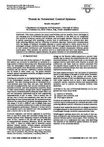
In this section we illustrate aspects of this approach with results from a detailed simulation of a border patrol scenario. The control structure in this simulation was specified in TEJA. The scenario considered in the simulation begins with a straight 15 km stretch of border specified by its endpoints, and three UAVs available for deployment. In this example there is one team controller for the region under surveillance. The team formation allocated the three UAVs to this team controller. After the initial allocation, the team controller divides the given border into three equally sized sectors, and allocates each UAV to reconnoiter a single sector based on minimum distance of each aircraft to the sectors. Each UAV patrols its sector, following an alternating spiral trajectory (spiral in, then spiral out). The trajectory is parameterized with a flyover time, which governs how tight the spiral is, and a safety factor, which governs how close to the boundaries of the sectors UAVs should fly (see [28] for details about the controller design and trajectory generation). The global flight paths, sector definitions, and radial constraints for each UAV are shown in figure 1. For simulation, we use kinematic models of the UAVs. The flight path of each UAV results into a ”rose” pattern within the sector.
2
0
−2
−4
0
5
10
15
X (km)
Fig. 2. Reconfiguration of sectors after one UAV is obliged to return to base. The border is divided into two sectors and the UAVs in sectors 1 and 2 (left and center) are reassigned to the new sectors.
based on range. Three aircraft start to patrol their respective sectors, as shown in figure 3. When a target is detected within range, the UAV that detected the target (the middle UAV) tracks it, and the other UAVs redistribute the area to be searched, as shown in figure 4. We are using fixed-wing UAV, which have a minimum air speed that they must maintain, which is likely to be faster than a pedestrian and then most ground vehicles. When following a slower target, the UAV will have to ”backtrack” and circle around the target. Spiral patterns make it easy to keep the target in the field-of-view of a gimballed camera. Flight path Sector Boundary (1+SF)Rmtr (1−SF)Rsec
4
0
Initial point Truck path −2
2
−4
0
Y (km)
Y (km)
2
−6
−2 2
4
6
8 X (km)
10
12
14
16 −4
Fig. 1. Three UAVs start off patrolling a 15km stretch of border split into three sectors. The UAV in Sector 3 (rightmost sector) is low on fuel and informs the team controller that it must return to base.
−6 2
In our first scenario, after a set time the UAV in the sector that is furthest to the right in the figure is low on fuel and must return to base. He communicates this information to the team controller and starts heading towards the base. The team controller then divides the border into two sectors and allocates them to the remaining UAVs, as shown in figure 2. In another scenario, a simple double integrator truck model was added to the simulation as well as a simple sensor model
4
6
8 X (km)
10
12
14
Fig. 3. Three UAVs start off patrolling a 15km stretch of border split into three sectors. A truck is detected by UAV in Sector 2 (middle sector).
VII. C ONCLUSIONS We have outlined a design for a surveillance system. We structure the geographic space as sub-regions. Each sub-region
Flight path Sector Boundary (1+SF)Rmtr (1−SF)Rsec
8
Initial point Truck path
6
Y (km)
4
2
0
−2
0
5
10
15
X (km)
Fig. 4. Reconfiguration of sectors between UAVs in sectors 1 and 3 after UAV2 Starts tracking a suspicious truck. The border is now split into two sectors instead of three, and the patrol paths have expanded in radius. The patrol trajectory is influenced by the choice of fly-over time, but the whole sector is patrolled eventually.
is placed under the control of a team controller which coordinates the sub-team controllers for that sub-region. The subteam controllers coordinate UAVs through their supervisors which, in turn, command and control maneuver controllers for each UAV. The structure of team controllers allows for the mobility of UAVs among them, for the re-allocation of subregions under their control, and for multiple types of mixed initiative interactions. There are several directions for future work. We are particularly interested in the issues of organization control, namely with the problem of endowing the control structure with mechanisms to guide its adaptation to evolving conditions of the world. ACKNOWLEDGMENT Jo˜ao Sousa was partially funded by the Luso-American Foundation Fellowship from the Portuguese Studies Program from the University of California at Berkeley. R EFERENCES [1] J. Jang and C. Tomlin, “Design and implementation of a low cost, hierarchical and modular avionics architecture for the dragonfly uavs,” in Proceedings of the 2001 AIAA Guidance, Navigation and Control Conference, Monterey, CA. AIAA, 2002, pp. 4465–4477. [2] S. Bayraktar, G. Fainekos, and G. Pappas, “Experimental cooperative control of unmanned aerial vehicles,” in Proceedings of the 43rd IEEE Conference on Decision and Control. IEEE, 2004, pp. 4292–98. [3] D. Shim, H. Kim, H. Chung, and S. Sastry, “A flight control system for aerial robots: Algorithms and experiments,” in Proceedings of the 15th IFAC World Congress on Automatic Control. IFAC, 2002. [4] V. Gavrilets, A. Shterenberg, M. Dehaleh, and E. Feron, “Avionics system for a small unmanned helicopter performing aggressive maneuvers,” in Proceedings of the Digital Avionics Systems Conference, 2000. [5] R. Hindman, R. Franz, and J. Hauser, “The virtual ducted fan: A control design and test platform for the caltech ducted fan,” in Proceedings of the 40th IEEE Conference on Decision and Control. IEEE, 2001. [6] M. van Nieuwstadt and R. Murray, “Real-time trajectory generation for differentially flat systems with unstable zero dynamics,” in Proceedings of the 15th IFAC World Congress on Automatic Control. IFAC, 1996.
[7] R. Beard, T. McLain, M. Goodrich, and E. Anderson, “Coordinated target assignment and intercept for unmanned air vehicles,” in Proceedings of the IEEE International Conference on Robotics and Automation. IEEE, 2002. [8] J. B. de Sousa, A. R. Girard, and J. Hedrick, “Elemental maneuvers and coordination structures for unmanned air vehicles,” in Proceedings of the 43rd IEEE Conference on Decision and Control. IEEE, 2004, pp. 608–614. [9] T. McLain and R. Beard, “Cooperative rendezvous of multiple unmanned air vehicles,” in Proceedings of the 2001 AIAA Guidance, Navigation and Control Conference, Denver, CO. AIAA, 2000, pp. 4369–4380. [10] P. Varaiya, T. Simsek, and J. B. de Sousa, “Communication and control of distributed hybrid systems - tutorial session,” in Proceedings of the 2001 American Control Conference. IEEE, 2001, pp. 4968–83. [11] T. McLain, P. Chandler, S. Rasmussen, and M. Pachter, “Cooperative control of uav rendezvous,” in Proceedings of the 2001 American Control Conference. IEEE, 2001, pp. 2309–2314. [12] P. Chandler, M. Pachter, and S. Rasmussen, “Uav cooperative control,” in Proceedings of the 2001 American Control Conference. IEEE, 2001, pp. 50–55. [13] R. Beard and T. McLain, “Multiple uav cooperative search under collision avoidance and limited range communication constraints,” in Proceedings of the 42nd IEEE Conference on Decision and Control. IEEE, 2003, pp. 25–30. [14] M. Godwin, K. Hedrick, and R. Sengupta, “A distributed system for the collaboration and control of unmanned aerial vehicles,” in Submitted to the IEEE International Conference on Robotics and Automation. IEEE, 2005. [15] J. Finke, K. Passino, and A. Sparks, “Cooperative control via task load balancing for networked uninhabited autonomous vehicles,” in Proceedings of the 42nd IEEE Conference on Decision and Control. IEEE, 2003, pp. 31–36. [16] S. Spry and K. Hedrick, “Formation control using generalized coordinates,” in Proceedings of the 43rd IEEE Conference on Decision and Control. IEEE, 2004, pp. 2441–2446. [17] M. Tillerson, L. Breger, and J. How, “Distributed coordination and control of formation flying spacecraft,” in Proceedings of the American Control Conference. IEEE, 2003, pp. 1740–1745. [18] M. Zennaro, J. Ko, R. Sengupta, and S. Tripakis, “A service network architecture for a multi-vehicle search mission,” in Proceedings of the 40th IEEE Conference on Decision and Control. IEEE, 2001, pp. 1503–8. [19] A. Zakarian and A. Kusiak, “Forming teams: an analytical approach,” IIE Transactions, vol. 31, pp. 85–97, 1999. [20] S. Russel and P. Norvig, Artificial Intelligence – A Modern Approach, ser. Prentice Hall Series in Artifical Intelligence. Prentice Hall Series in Artifical Intelligence, 1995. [21] J. Ferber, An introduction to distributed artificial intelligence. AddisonWesley, 1999. [22] P. Varaiya, “http://paleale.eecs.berkeley.edu/ varaiya/papers ps.dir/ mica final.pdf,” 2004. [23] ——, “Towards a layered view of control,” in Proceedings of the 36th IEEE Conference on Decision and Control. IEEE, 1997, pp. 1187–90. [24] ——, “Smart cars on smart roads: problems of control,” IEEE Transactions on Automatic Control, vol. 38, no. 3, pp. 195–207, February 1993. [25] J. B. de Sousa, A. Girard, and K. Hedrick, “Real-time hybrid control of mobile offshore base scaled models,” in Proceedings of the American Control Conference. IEEE, 2000. [26] J. B. de Sousa and F. L. Pereira, “A generalized vehicle-based control architecture for multiple auvs,” in Proceedings of the OCEANS ’95 MTS/IEEE. IEEE, 1995, pp. 1643–50. [27] J. B. de Sousa, P. Varaiya, and T. Simsek, “Task planning and execution for uav teams,” in Proceedings of the 43rd IEEE Conference on Decision and Control. IEEE, 2004, pp. 3804–10. [28] A. Girard, A. Howell, and K. Hedrick, “Border patrol and surveillance missions using multiple unmanned air vehicles,” in Proceedings of the 43rd IEEE Conference on Decision and Control. IEEE, 2004, pp. 620–625.