Guo, Thomas.Heuze, Ramzi.Othman, Guillaume.Racineux}@ec-nantes.fr. AbstractâSplit-Hopkinson Pressure Bar (SHPB) is a conven- tional apparatus for ...
Dynamic testing with modified Hopkinson-bar at very high-strain rate X. Guo1 , T. Heuz´e1 , R. Othman1,2 , G. Racineux1 1
LUNAM Universit´e, GeM, UMR CNRS 6183, Ecole Centrale de Nantes, Universit´e de Nantes, France 2 Mechanical engineering department, Faculty Engineering, King Abdulaziz University P.O.BOX, 80248, Jeddah, 21589, Saudi Arabia {Xiaoli.Guo, Thomas.Heuze, Ramzi.Othman, Guillaume.Racineux}@ec-nantes.fr
Abstract—Split-Hopkinson Pressure Bar (SHPB) is a conventional apparatus for testing the dynamic stress-strain response of materials at strain rate up to 104 s−1 [1]. In this work, a directimpact equipment with smaller bar are carefully designed based on a series of criteria. The aim is to attain the strain rate up to 105 s−1 . Preliminary tests are performed with this direct-impact system on aluminium alloy AA2017 and titanium alloy Ti-6Al4v. Projectiles of different lengths have been used to impact the specimens of different thickness to extend the strain rate. Strain rate up to 2×10⁴ s−1 on AA2017, 4×10⁴ s−1 on Ti-6Al4V have been reached in the preliminary tests with this directimpact system. Keywords - Hopkinson-bar, Very high-strain rate, Directimpact
I. I NTRODUCTION Split-Hopkinson Pressure Bar (SHPB) is a conventional apparatus for testing the dynamic stress-strain response of materials. Based on the unidimensional theory, the apparatus consists of a projectile, an input bar, an output bar and a buffering device. During testing, the projectile strikes on the input bar and generates a dynamic stress in the apparatus. A wave propagates through the input bar, then deforms the specimen and is finally transmitted to the output bar. The gauges stuck on the input and output bars capture the axial strain induced by the propagation of the pressure waves. Considering the unidimensional theory of the wave propagation, the stressstrain relationship of the tested material can be expressed by the deformation measured by the gauges. [1]–[3] σs =
Ab Eb (�I + �R + �T ) 2As
�˙s = −
cb (�I − �R − �T ) ls Z
�s
=
(1) (2)
t
�˙s (τ ) dτ
(3)
0
where σs ,�s ,�˙s ,As ,ls denote the stress, strain, strain rate, section and length of the specimen respectively; cb ,Eb are the wave velocity and young’s modulus of the bars; �I ,�R ,�T
are the strains incident by input wave, reflected wave and transmitted waves [1]–[3]. Traditional SHPB system can perform the test at strain rate up to 104 s−1 . Generally, three modifications can be adopted to extend the range of the strain rate [1]: •
•
•
Decrease the length of the specimen. The reduction of the dimension of the specimen is limited by the dimension of the bars to ensure a good signal. Miniaturization of the entire system is good approach to test much smaller specimen. To increase the impact velocity and avoid to yield the input bar, the input bar can be discarded to impact the specimen directly. The gauges fixed on the output bar record the strain �T . Moreover, a high speed camera is used to measure the velocity of the projectile V1 during the impact. Then the stress-strain of the specimen can be calculated by [1]–[3]: Ab Eb �T As
(4)
(V1 − cb �T ) ls
(5)
σs = �˙s =
Z �s
=
t
�˙s (τ ) dτ
(6)
0
With the modified Hopkinson-bar, the tests can be carried out at strain rate much higher than 104 s−1 . Gorham [4] has obtained the strain rate of 4 × 10⁴ s−1 with a directimpact system; Kamler [5] has developed a miniaturization system to perform experiments on copper at the strain rate of 6 × 10³ s−1 to 4 × 10⁵ s−1 . Casem, Grunschel and Schuster [6] have performed the test on 6061-T6 beyond the strain-rate of 105 s−1 with the very small bar of 1.6mm in diameter. To perform the test at the strain rate higher than 104 s−1 on highstrength material, such as the titanium alloy, a direct-impact system is designed. Preliminary tests have been performed with this system.
Specimen ∗ �min < �∆t s < �max ∗ (buckling) 21 < φlss < 32 ("flange") 6
� ∗ �∆t s = ∗
R 2lp /cp
1 2 2 ρp Sp lp Vp
0
−�˙s |< T olerance
� -
Output bar + gauges ∗ φ b � lb ∗ Buckling �
@ I @ @ @ @ @ @ @ @ R @
∗ lp ≥ α
cb lp +10 φb |{z} cp |{z}
∆tb > ∆texp
∗ li ≥ Fig. 1.
Design criteria of direct-impact system
Fig.1 shows the relationship and mutual restriction of the dimensions of the components in the direct-impact system. All these restrictions can be summarized into 3 basic criteria [1]–[3] :
•
•
"3D"→"1D"
2c l α cbp p
II. E STABLISHMENT OF DIRECT- IMPACT SYSTEM Design
•
Energy criteria: Although the input kinetic energy of the projectile is limited by the capability of the cannon, it should be large enough to ensure an exploitable deformation of the output bar recorded by the gauges, while avoiding to destroy the gauges. Projectiles of different lengths (125mm, 60mm, 30mm,20mm) have been manufactured to increase the impact velocity being given a yield input energy. Unidimensional criteria: the lateral inertia effect during the wave propagation should be within the allowable range. Furthermore, the diameter of the specimen should be smaller than that of the projectile and the output bar due to the dilatation of the lateral dimension during the deformation. The ratio between the length and the diameter of the specimen should range from 0.5 to 2 to avoid buckling or large friction at the interfaces. Equilibrium criteria: The equations mentioned above are based on the achievement of force equilibrium during the
test. Typically, the wave length should be much larger than the length of the specimen due to the multiple reflection of loading wave between two interfaces. Other factors such as the machining feasibility should be also considered. Diameter of output bar The loading wave propagates in different forms in the output bar. Only the 1st -mode wave is required to approach a homogeneous stress state throughout the section of the bar, which allows to avoid to perform an inverse analysis to deduce the stress into the specimen. This involves a restriction on the diameter of the output bar. The Pochhammer-Chree [13], [14] is expressed as [12], ϕ(ξ, ω, E, ν, r, ρ)
2
2 2 = 2α r (β + ξ )J1 (αr)J1 (βr) 2 2 2 − (β − ξ ) J0 (αr)J1 (βr) − 4αβξ 2 J1 (αr)J0 (βr) = 0 2
(7)
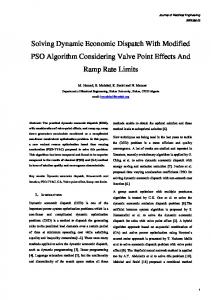
ρω in which, α2 = λ+2µ − ξ 2 ; β 2 = ρωµ − ξ 2 . Jn () is the first kind Bessel function of order n; ξ(ω) is the wave number with respect to the angular frenquency ω; ν, λ and µ, E, ρ denote the Poisson’s ratio, Lam´e’s constants, Young’s modulus and density respectively. When the wave number ξ = 0, the solution of the Pochhammer-Chree equation gives the relationship between
9
2.5
x 10
φ4mm φ5mm
AA2017 Ti-6Al-4V
thickness: 3mm, 2mm thickness: 3mm, 2mm, 1.5mm
2
After the test, signals of the gauges are processed to get the deformation of the output bar. With this deformation, the stress and strain of the specimen can be calculated. Fig.5 shows the stepping of the post-treatment ( [1], [7]–[9]).
σ (Pa)
1.5
1
gauge signal �v ⇒ �b of bar
0.5
?
0 −0.5
0
Fig. 2.
0.5 ε
1
1.5
Exciting signal (Ti-6Al-4V behviour)
angular frequency (rad/s)
? specimen: σs = Eb �b Sb /Ss
6
18
calibration of dispersion [8], [10]
�˙s =
x 10
16
ωc (cut−off angular frequency)
14
ω2 (angular frequency for 2nd mode)
1 [v ls 0
? + cb �b (1 +
�s0 =
R? τ 0
Sb )] Sp
�˙s dt
12
?
calibration of punch effect [7]: �s = �s0 − �punch
10 8 6
?
4
Engineering (σs , �s ) to True (σt , �t ) [1]: �t = ln(1 + �s ) σt = σs ∗ (1 + �s )
2 0
5
10
15 radius (mm)
20
25
30
? Fig. 3.
create elastic stage
Cut-off frequency and 2nd -mode-wave frequency
? the angular frequency ω and the radius r of the bar. Furthermore, the angular frequencies of different modes have the relationship as ω1 = 0 < ω2 < ω3 < · · ·. The stress of the testing material is the exciting source of the output bar. Ti-6Al-4V is the main testing material, and it is assumed to follow the Johnson-Cook constitutive law [15], [16]. The cutoff frequency ωc can be obtain by Fourier Transforming the exciting signal in fig.2. Considering ωc as the lower bound, the range of the radius of the bar can be defined(3). Based on this principal, the bar of 10mm in diameter and 1.20m in length is manufactured as the output bar. The bar and projectiles are made of a high-strengh steel (MARVAL, X2NiCoMo18-8-5), of which the yield stress is 1800MPa.
create σ − � curve Fig. 5.
Results For the material of Ti-6Al-4V and AA2017, the yield stress is not obvious from the stress-strain curve. So the stress with an offset of the strain (0.2%) is defined here as the yield stress (σp0.2 ). The curve of the yield stress of both materials is plotted as the function of the strain-rate in fig.6 to observe the strain-rate sensitivity. •
III. DYNAMIC TEST Experiments The dynamic tests are performed with the direct-impact system (fig.4). Both sides of the specimen are lubricated to reduce friction. 3 Wheatstone bridge with double gauges are cemented on the output bar, close to the two ends and in the middle in order to record the deformations. Tests are performed at room temperature. Aluminium alloy AA2017 and titanium alloy Ti-6Al-4V have been tested at strain-rate up to 2×10⁴ s−1 and 4×10⁴ s−1 respectively. The dimension of the specimen are as follows:
Process of post-treatment
•
•
For both materials, within the range of strain-rate from 4×10³ s−1 to 2×10⁴ s−1 ), the strain-rate sensitivity is not obvious, especially for AA2017. The stress σp0.2 changes approximately linearly with the logarithm of the strainrate. The average yield stress ranges from 300MPa to 500MPa for AA2017, and from 1000MPa to 1300MPa for Ti-6Al-4V. With the strain-rate higher than 2 × 10⁴ s−1 for Ti-6Al4V, the stress increases strongly with the increase of the strain rate. Moreover, the yield stress is around 1800MPa at the strain rate from 3 × 10⁴ s−1 to 4 × 10⁴ s−1 . The results of the preliminary tests performed with the direct-impact system need to be verified.
Fig. 4.
Direct-impact system
2000
σp0.2 (MPa)
1500
1000
500
0 0
AA2017 Ti−6Al−4V 0.5
1
1.5
Fig. 6.
2 2.5 dε/dt (s−1)
3
3.5
4 4
x 10
σp0.2 - �˙
IV. C ONCLUSION •
•
•
•
A direct-impact system with a slenderer output bar is designed based on the complicated criteria and established; Preliminary tests are performed on AA2017 and Ti6Al-4V at strain rate of 2 × 10⁴ s−1 and 4 × 10⁴ s−1 respectively. From the present results, the yield stress is quite high at the strain rate higher than 2 × 10⁴ s−1 . The inappropriate definition of the yield stress may be the cause of this problem. So the definition of the yield stress should be improved; The verification of the results and calibration of the direct-impact system are still ongoing. ACKNOWLEDGMENT
The first author is financed by China Scholarship Council. R EFERENCES [1] K. T. Ramesh. Part D: Chapter 33. High strain rate and impact experiments.
[2] Dominique Franc¸ois, mcaniques et lois de comportement, Chaptre 9, 250-283. 2001. [3] Stress waves in solids. H.Kolsky [4] D. A. Gorham: Measurement of stress-strain properties of strong metals at very high strain rates, Inst. Phys. Conf. Ser. 47, 1624 (1980) [5] F. Kamler, P. Niessen, R.J. Pick: Measurement of the behaviour of highpurity copper at very high rates of strain, Canad. J. Phys. 73, 295303 (1995) [6] D. T. Casem, S. E. Grunschel, B. E. Schuster: Normal and transverse displacement interferometers applied to small diameter Kolsky bars. Experimental Mechanics(2012)52:173-184 [7] Safa K., Gary G. Displacement correction for punching at a dynamically loaded bar end, IE-1835, International Journal of Impact Engineering 37, 2010, 371-384 [8] G.Gary, J. R. KLEPACZKO, H, ZHAO, Correction de dispersion pour l’analyse des petites deformation aux barres de Hopkinson, Journal de Physique IV, 1(1991),C.3, 403-410 [9] H. Zhao and G. Gary, On the use of SHPB technique to determine the dynamic behaviour of the materials in the range of small strains, Int.J.Solid. & Structure. 33(1996),3363-3375 [10] R.Othman, R. H. Blanc, M. Bullac, P. Collet, G.Gary, Identification de la relation de dispersion dans les barres. C.R. Mecanique 330(2002)849855 [11] Len Schwer, Optional strain-rate forms for the Johnson Cook constitutive model and the role of the parameter epsilon 0. 6th European LS-DYNA Users Conference [12] R. Othman. Cut-off frequencies induced by the length of strain gauges measuring impact events. STRAIN. 48(2012)15-20 [13] L. Pochhammer, Uber die fortpflanzungsgeschwindigkeiten kleiner schwingungen in einem unbergrenzten isotropen kreiszylinder. J.fiir die Reine und Angewande Mathematic 81,324-336. 1876 [14] C. Chree. The equations of an isotropic elastic solid in polar and cylindrical co-ords, their solution and applications. Cambridge Phil. Soc. Trans. 14,250-369. 1889 [15] G. R. Johnson, W. H. Cook, A constitutive model and data for metals subjected to large strains, High strain rates and high temperatures. [16] H. K. Amarchinta, R. V. Grandhi, K. Langer, D. S. Stargel, Material model validation for laser shock peening process simulation, Modelling and Simulation in Materials Science and Engineering, 17(2009)015010