Mar 13, 2009 - SE, Kirtland Air Force. Base, New Mexico 87117, USA. Received 11 November 2008; accepted 15 January 2009; published online 13 March ...
CHAOS 19, 013127 共2009兲
Dynamical mechanism of intrinsic localized modes in microelectromechanical oscillator arrays Qingfei Chen,1 Liang Huang,1 Ying-Cheng Lai,1,2 and David Dietz3 1
Department of Electrical Engineering, Arizona State University, Tempe, Arizona 85287, USA Department of Physics, Arizona State University, Tempe, Arizona 85287, USA 3 Air Force Research Laboratory, Directed Energy Directorate, 3550 Aberdeen Ave. SE, Kirtland Air Force Base, New Mexico 87117, USA 2
共Received 11 November 2008; accepted 15 January 2009; published online 13 March 2009兲 Experimental evidence of intrinsic localized modes 共ILMs兲 in microelectromechanical oscillator arrays has been reported recently. In this paper, we carry out a detailed analysis of a new mechanism for ILMs in typical experimental settings; that is, spatiotemporal chaos is ubiquitous and it provides a natural platform for actual realization of various ILMs through frequency control. We find that unstable periodic orbits associated with ILMs are pivotal for spatiotemporal chaos to arise and these orbits are the keys to stabilizing ILMs by frequency modulation. © 2009 American Institute of Physics. 关DOI: 10.1063/1.3078706兴 Small-sized systems such as microelectromechanical (MEM) resonators have become common in many fields of science and engineering. These systems have a relatively simple structure but they show surprisingly rich nonlinear-dynamical behaviors such as bistability, chaos, and energy-localized oscillations. This paper focuses on intrinsic localized modes (ILMs) in MEM oscillator arrays. The phenomenon is characterized by the oscillations of a few oscillators with significantly larger amplitudes than the average amplitude. While ILMs have been identified in a wide variety of physical systems such as Josephson junctions, optical waveguide arrays, photonic crystals, and antiferromagnets, their discovery in MEM systems has been relatively recent. We shall report results from numerical computations and dynamical analysis of a generic class of MEM oscillator arrays, which suggest the fundamental role played by chaotic dynamics in generating ILMs. In particular, we find that spatiotemporal chaos provides a natural platform for ILMs. As MEM systems are employed extensively in device research and development, we expect our finding to be potentially useful. I. INTRODUCTION
ILMs, also known as “discrete breathers” or “lattice solitons,” can occur in a defect-free nonlinear lattice, extending over only a few lattice sites.1–4 In basic physics, ILMs represent an interesting phenomenon as they are the result of purely nonlinear interactions. Theoretically, for conservative systems, the localized modes are exact solutions.5,6 In device applications, ILMs can be of significant concern as localized high-energy states can have undesirable effects on the operation of the device. ILMs have in fact been observed in many physical systems, such as Josephson junctions,7 optical waveguide arrays,8 photonic crystals,9 and antiferromagnets.10 Recently, ILMs have been discovered experimentally in MEM oscillator arrays.11,12 As such systems are the key com1054-1500/2009/19共1兲/013127/9/$25.00
ponents in state-of-the-art technologies that are having ever increasing impacts on various areas of science and engineering,13 it is of considerable interest to explore the dynamical mechanism of ILMs in MEM oscillator arrays. The purpose of this paper is to offer a detailed analysis for the mechanism of ILMs in experimental systems. In particular, a route for exciting ILMs in MEM oscillator arrays through spatiotemporal chaos is presented. While the dynamical mechanism of ILMs in conservative systems has been understood reasonably well,5,6 systems of MEM oscillator arrays are typically dissipative. Prior to our work, the status of understanding of ILMs in MEM oscillator arrays is as follows. It has been suggested that artificial impurities in MEM cantilever arrays can induce ILMs,14 and ILMs induced by a forced nonlinear vibration mode have also been realized.15 However, there is experimental evidence indicating that ILMs can be generated without any impurities.12 In Ref. 16, besides ILMs, phenomena such as hopping and repulsion are reported, but the underlying mechanisms of these phenomena are not given. Computational study of MEM cantilever arrays of identical beam length has revealed that it is not possible to have modulational instability in the system, but ILMs can be generated by noise in combination with frequency chirping modulation.17 The conclusion appears to be that, in order for a MEM oscillator-array system to exhibit ILMs, the following two conditions are needed: 共1兲 random heterogeneous initial conditions or noise and 共2兲 modulation of driving frequency in time 共frequency chirping兲. The starting point of our analysis is a prototype system described by a set of coupled differential equations derived from experiments.11 Since typical experimental settings to excite ILMs include the case where periodic forcing is applied to MEM arrays of alternating lengths, i.e., a long 共short兲 beam has two short 共long兲 beams as its nearest neighbors, one on each side,11,12 we will consider both the uniform-length and the alternating-length cases. The method of averaging can then be employed to reduce the system to a
19, 013127-1
© 2009 American Institute of Physics
Downloaded 30 Mar 2009 to 129.219.51.205. Redistribution subject to AIP license or copyright; see http://chaos.aip.org/chaos/copyright.jsp
013127-2
Chaos 19, 013127 共2009兲
Chen et al.
A
冋 冉 冊册
2u 4u u u 2u + EI + EI t2 s4 s s s s s2 = A␣ cos共⍀t兲,
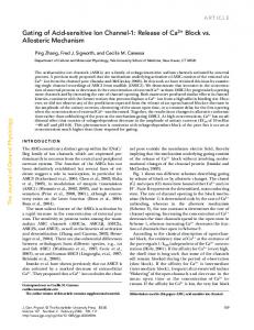
FIG. 1. 共Color online兲 Schematic of a single cantilever unit in a typical experimental MEM array system, where L1, L2, W1, W2, T, P, and H denote the beams’ lengths, widths, thickness, length of the pitch, and length of the overhang, respectively.
form for which, in the zero-coupling limit, all possible equilibrium solutions can be obtained and their stabilities can be determined. Analytic continuation of the solutions into the finite-coupling regime reveals the coexistence of both locally high- and low-energy states 共LESs兲, which is a necessary condition for ILMs in MEM oscillator arrays. We find that, for the alternating-length case, spatiotemporal chaos can arise when the LES loses its stability, and ILMs can be excited naturally from chaos by frequency modulation, which can be abrupt with even uniform initial conditions for all oscillators in the absence of any external noise. A brief account of this phenomenon has been reported recently.18 In this paper, we carry out a detailed, systematic analysis of the dynamical mechanism for ILMs. Issues such as the existence of ILM states, their stabilities and bifurcations, the occurrence of spatiotemporal chaos, and the stabilization of ILMs from chaos by frequency modulation will be addressed. In Sec. II, we describe the physics that leads to a generic model for MEM oscillator arrays, suitable for nonlineardynamics-based analysis. In Sec. III, the dynamics of ILMs are studied in detail. The mechanism for generating spatiotemporal chaos is investigated in Sec. IV, and the route to ILMs via chaos is demonstrated in Sec. V. Conclusions and discussion are presented in Sec. VI.
II. MODEL
The geometry of a single cantilever unit in a coupled MEM oscillator array employed in experimental studies12 is shown in Fig. 1, where two cantilevers with alternating length are coupled by an overhang. The corresponding MEM array system can be fabricated by low-stress silicon nitride. Driving of the array is realized by a piezoelectric transducer. The material properties of the system are11,16 L1 = 50 m, L2 = 55 m, W1 = W2 = 15 m, T = 0.3 m, H = 23 m, and P = 40 m. The density and Young’s modulus of the material are = 2300 kg/ m3 and E = 110 GPa, respectively. The dynamics of a MEM cantilever beam is in general described by a nonlinear partial differential equation19 that involves complicated mechanical and electrical interactions between the beam and its surroundings. For a single cantilever beam, the continuum equation of motion under driving force is11
共1兲
where A = W ⫻ T is the cross-sectional area of the beam and I = 共W ⫻ T3兲 / 12 is the moment of inertia. The displacement variable u共s , t兲 can be expanded based on a set of orthonormal shape functions, denoted by n共s兲, as follows: u共s,t兲 = 兺 n共s兲n共t兲,
共2兲
n
where n共t兲 is the beam tip’s displacement associated with n. The shape functions satisfy the boundary conditions n共0兲 = 0 and n共L兲 = 1. Here, only the lowest frequency mode is kept. By substituting Eq. 共2兲 into Eq. 共1兲, multiplying 1共s兲 on both sides, and then integrating the equation over the length of the beam, one can obtain m
d2x共t兲 + k2x共t兲 + k4x3共t兲 = m␣ cos共⍀t兲, dt2
共3兲
where x共t兲 is the displacement of the beam’s tip and k2 = 共12.36EI兲 / L3 and k4 = 共24.79EI兲 / L5 are the harmonic and the quadratic spring constants,11 respectively. For coupled microcantilever arrays, the full dynamical equations are more complicated. The cantilevers are affected by their environment, generating various damping forces. They also interact with each other with coupling forces. Without losing the essential dynamics of the system, we focus on the motions of the free ends of the beams, taking into account damping and coupling effects. The system equations can then be described by the following set of nonlinear ordinary differential equations:12 mix¨i + bix˙i + k2ixi + k4ix3i + kI共2xi − xi+1 − xi−1兲 = mi␣ cos共2 ft兲,
共4兲
where xi 共i = 1 , . . . , N兲 is the displacement of the end point of the ith cantilever beam of effective mass mi, bi is the damping coefficient, k2i and k4i are the on-site harmonic and quadratic spring constants of the ith beam, respectively, and kI is the harmonic coupling spring constant which we choose as a bifurcation parameter of the system. Each beam is subject to a common sinusoidal driving characterized by acceleration ␣ and frequency f. Let ⍀ = 2 f and xi共t兲 = Ui共t兲cos共⍀t兲 + Vi共t兲sin共⍀t兲 and define Qi = 冑mik2i / bi and ⍀0i = 冑k2i / mi as the quality factor and the resonant frequency of beam i, respectively. When the driven frequency ⍀ is close to the resonant frequency and when the driving is strong, the beam dynamics can be strongly nonlinear, exhibiting a bistable response with either large- or small-amplitude oscillations. Moreover, in the bistable region, there exists an unstable solution between the two stable solutions. We first consider the situation where all beams have identical length. The MEM array system equation 共4兲 is in fact a system of coupled driven Duffing oscillators. The averaging technique20,25 can then be employed for moderate driven force. Let the averaged functions of Ui共t兲 and Vi共t兲 be ui共t兲 and vi共t兲, respectively. A straightforward averaging procedure leads to
Downloaded 30 Mar 2009 to 129.219.51.205. Redistribution subject to AIP license or copyright; see http://chaos.aip.org/chaos/copyright.jsp
013127-3
Chaos 19, 013127 共2009兲
Dynamical mechanism of ILMs
冋
−5
1 3 k4i dui ⍀0i 2 =− 共⍀2 − ⍀0i 兲vi − ⍀ui vi共u2i + v2i 兲 + 4 mi dt 2⍀ Qi
册
册
U3
U2
0.6
U4
1
共5兲
0.4 k
0.2
kB
B
1
2
S2
kI 共2ui − ui+1 − ui−1兲 , mi
i = 1, . . . ,N,
0 0
(a)
which is in a form of a discrete nonlinear Schrodinger equation 共NLSE兲20 driven by a constant force ␣ / 共2⍀兲,
kI 共2i − i+1 − i−1兲 + 2⍀mi
S3 k
In this section, we systematically investigate the dynamics of ILMs in MEM oscillator arrays. We first study the dynamics of two coupled MEM oscillators and then extend the analysis to systems of larger numbers of oscillators.
k
B
0.6
B
2
1
U2
2
III. DYNAMICS OF ILMS IN MEM OSCILLATOR ARRAYS
0.015 S1
x 10
0.8
共6兲
for i = 1 , . . . , N, where i = ui + jvi. For uniform beam length, Eq. 共6兲 has a continuum limit. However, for the case of alternating beam length, Eq. 共6兲 does not have the continuum limit and can only be analyzed as a coupled lattice system. Another difference between Eq. 共6兲 and the standard coupled NLSE is that, for the latter, the coefficient of the first-order term on the right-hand side is complex.
0.01
−5
1
A (m)
册
3 k4i 1 ⍀0i di ␣ 2 =− 共⍀2 − ⍀0i 兲+j i + 兩 i兩 2 i − j 8 ⍀mi dt 2Qi 2⍀ 2⍀
kI (N/m)
0.4
U1
U4 U3
0.2 S2
0 (b) 0
k (N/m) I
0.01
0.015
−5
1
x 10
A6
0.8
A1,2,...,11(m)
冋
S3
U1
1 3 k4i dvi ⍀0i 2 = 共⍀2 − ⍀0i 兲ui − ui共u2i + v2i 兲 − ⍀vi + ␣ 4 mi dt 2⍀ Qi −
S1
0.8
kI 共2vi − vi+1 − vi−1兲 , mi
冋
x 10
A (m)
−
1
k
B
0.2
(c)
0 0
k (N/m) I
0.008 0.01
A. Two coupled MEM oscillators
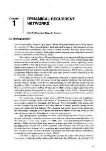
A key feature of ILMs is the coexistence of two groups of oscillators with high and low energies, respectively. To gain insight, we first study the case of two coupled oscillators. Although the case of coupled undamped NLSEs has been discussed in Ref. 21, to our knowledge, the driven damped NLSEs with complex coefficient which describe coupled MEM oscillator systems have not been studied. Here, we discuss the case of coupled beams of identical lengths. Since Eq. 共5兲 governs the evolution of the averaged motion, its equilibrium solutions correspond to oscillatory solutions of the actual system. A viable approach is to set kI = 0 to find all possible equilibrium solutions for the decoupled system and then analytically continue the solutions as kI is increased from zero. Figures 2共a兲 and 2共b兲 show projections of the amplitudes of the averaged oscillations A1 = 冑u21 + v21 and A2 = 冑u22 + v22 versus kI, respectively, where A1 ⬎ A2 共the case A2 ⬎ A1 is symmetrical兲. Parameters are chosen according to their corresponding experimental values:12
(d) FIG. 2. Projections of solution locus: 共a兲 A1 = 冑u21 + v21 vs kI and 共b兲 A2 = 冑u22 + v22 vs kI for N = 2. As kI is decreased through the value denoted by the vertical line kB1, a S-N bifurcation occurs. The vertical line kB2 denotes an unstable-unstable pair bifurcation. Oscillations of distinct amplitudes occur for 0 ⱕ kI ⬍ kB1. 共c兲 For a system of N = 11 beams, equilibrium solutions Ai vs the coupling parameter kI. ILMs are possible for 0 ⬍ kI ⬍ kB ⬇ 0.008 N / m. 共d兲 A representative ILM state.
共mi,bi,k2i,k4i, f, ␣兲 = 共5.46 ⫻ 10−13 kg, 6.24 ⫻ 10−11 kg/s, 0.303 N/m, 5 ⫻ 108 N/m3, 1.25 ⫻ 105 Hz, 1.56 ⫻ 104 m/s2兲.
Downloaded 30 Mar 2009 to 129.219.51.205. Redistribution subject to AIP license or copyright; see http://chaos.aip.org/chaos/copyright.jsp
013127-4
Chaos 19, 013127 共2009兲
Chen et al.
there are three homogeneous solutions 共denoted as HOSs兲 where the dynamical states of the two oscillators are identical, that is, HOS1:兵共A1, 1,A2, 2兲兩A1 = M 1, 1 = T1,A2 = M 1, 2 = T1其, HOS2:兵共A1, 1,A2, 2兲兩A1 = M 2, 1 = T2,A2 = M 2, 2 = T2其, and HOS3:兵共A1, 1,A2, 2兲兩A1 = M 3, 1 = T3,A2 = M 3, 2 = T3其, and three heterogeneous solutions 共HESs兲, HES1:兵共A1, 1,A2, 2兲兩A1 = M 1, 1 = T1,A2 = M 2, 2 = T2其, HES2:兵共A1, 1,A2, 2兲兩A1 = M 1, 1 = T1,A2 = M 3, 2 = T3其, and FIG. 3. 共Color online兲 Time series x1共t兲 and x2共t兲 共thin solid and dashed traces兲 of unsynchronized solution U1 and their amplitudes obtained by the averaged model 共thick horizontal solid and dashed lines兲 for KI = 0.005 N / m.
There are three synchronized solutions denoted by S1, S2, and S3 and four unsynchronized solutions labeled U1, U2, U3, and U4. The stable 共unstable兲 solutions are represented by solid 共dashed兲 lines. The vertical line denoted by kB1 indicates a saddle-node 共S-N兲 bifurcation point. We see that in the parameter region kI ⬍ kB1, there is a stable equilibrium solution 共U1兲 for which the oscillation amplitudes of the two beams are quite different, besides the existence of stable synchronized motions, which has the feature of ILM. To justify the use of the averaged system for approximating the driven system equation 共4兲, we plot the time series x1共t兲 and x2共t兲 obtained directly from Eq. 共4兲 共thin traces兲 and the amplitudes from the averaged system, as shown in Fig. 3 for KI = 0.005 N / m. We observe that the amplitudes of the time series agree with those from the averaged system very well. We can now analyze the distinct dynamical states and their origins by focusing on the solutions in the decoupled limit 共or anticontinuous limit兲 of Eq. 共5兲 where kI = 0. A decoupled system can be transformed into polar coordinate as
冋
册
1 dAi ⍀⍀0imiAi = − − mi␣ sin i , dt 2⍀ Qi
冋
册
3k4iA3i 1 di 2 − mi␣ cos i , = 共⍀0i − ⍀2兲Ai + 4 dt 2⍀Ai
共7兲
where Ai = 冑u2i + v2i and i are the radial and angular coordinates of 共ui , vi兲 共Ai and i also denote the amplitude and the phase angle of xi, respectively兲. Consider the static solutions at the decoupled limit of system 共5兲. There are in total three hyperbolic equilibria for each subsystem 共7兲: S1i ª 兵共Ai , i兲 兩 Ai = M 1 , i = T1其, 2 Si ª 兵共Ai , i兲 兩 Ai = M 2 , i = T2其, and S3i ª 兵共Ai , i兲 兩 Ai = M 3 , i = T3其, where i = 1 , 2, M 1 = 2.5218⫻ 10−7 m, M 2 = 9.6173 ⫻ 10−6 m, M 3 = 9.3655⫻ 10−6 m, T1 = 1.0005, T2 = −0.0176, and T3 = −0.9828. For the case of A1 ⱖ A2, there are six solutions at the decoupled limit. In particular,
HES3:兵共A1, 1,A2, 2兲兩A1 = M 2, 1 = T2,A2 = M 3, 2 = T3其 共the other three HESs for A2 ⬎ A1 are considered to be the same as HES1, HES2, and HES3 due to symmetry兲. Among these solutions, HOS3, HES2, and HES3 are unstable since they have the unstable equilibrium S3i in at least one of the two subsystems. Since all the solutions at the decoupled limit are hyperbolic, when the value of kI is continued from 0, the stabilities of the solutions can be maintained, as stipulated by the local stability theorem.26 In Figs. 2共a兲 and 2共b兲, the solutions S2, S1, and S3 originate from HOS1, HOS2, and HOS3, respectively, and the solutions U1, U3, and U2 are extensions of HES1, HES2, and HES3, respectively. Since ILMs are spatially heterogeneous and are physically observable, they can only be continued from stable HESs. Therefore, among the solutions in Figs. 2共a兲 and 2共b兲, only U1 satisfies the condition and represents an ILM. B. N „N > 2… coupled MEM oscillators
We now treat the general case of N ⬎ 2. Following the same approach as for the N = 2 case, we note that, in the bistable regime, a single, decoupled beam has three hyperbolic equilibria: two stable and one unstable. For kI = 0, there are 3N hyperbolic equilibria. As these solutions are analytically continued from kI = 0, their number and stabilities remain the same, as guaranteed by the local stability theorem. There thus exists a finite parameter regime kI ⲏ 0 in which each beam has two possible stable solutions: one of small and the other of large amplitude. An ILM corresponds to the situation where a few of the beams are in the large-amplitude state, while the remaining beams oscillate with small amplitudes. An examination of the basin structure of the singlebeam dynamics reveals that the basin of the large-amplitude stable equilibrium is typically much smaller than that of the small-amplitude stable equilibrium. Thus, from random heterogeneous initial conditions, majority of the beams oscillate with small amplitude in the steady state while only a few may oscillate with relatively large amplitude. This indicates that, from the viewpoint of dynamics, ILMs are generic in the sense that the opposite situation where many more beams oscillate with large amplitude is typically unlikely. Physi-
Downloaded 30 Mar 2009 to 129.219.51.205. Redistribution subject to AIP license or copyright; see http://chaos.aip.org/chaos/copyright.jsp
013127-5
Dynamical mechanism of ILMs
cally, ILMs also represent collective motions of the system that are energetically favorable. To illustrate how our analysis works, we present an example of finding an ILM for N = 11, where the sixth beam oscillates with a high amplitude. In this case, we study the beam arrays with identical beam lengths and the parameters are set to be the same as the ones employed in Figs. 2共a兲 and 2共b兲. A solution for kI = 0 thus represents the state where this beam is initiated in the high-amplitude basin while the remaining ten beams are initially set to oscillate with low amplitude. Numerically obtained continuation of these solutions as kI is increased from zero is shown in Fig. 2共c兲, where the vertical line at kB denotes a S-N bifurcation point, beyond which only synchronized beam dynamics can occur. ILMs can be found for 0 ⬍ kI ⬍ kB ⬇ 0.008 N / m. The spatiotemporal evolution of the beam energies is shown in Fig. 2共d兲 for kI = 0.005 N / m, where a spatially localized behavior in the energy can be seen. While a stability analysis indicates that ILMs can arise typically in MEM oscillator arrays, it does not guarantee that ILMs can actually be observed in, for instance, a specific experiment. In previous works concerning MEM arrays with alternating beam lengths,12,16,17 it has been argued that, in order for ILMs to occur, 共1兲 the initial state of the MEM beam system should be random to allow for spatial heterogeneity and 共2兲 the frequency of the external driving should be increased gradually with time 共frequency chirping兲 to enhance the heterogeneity. Our computations reveal, however, that both conditions can be relaxed. In particular, the degree of heterogeneity in the initial condition distribution can be made arbitrarily small. For instance, we can actually use null initial conditions for all beams. A new finding is that spatiotemporal chaos can occur typically in the parameter regime of low driving frequency due to the uneven distribution of the beam length, which can serve as the source of spatial heterogeneity for beam dynamics. Because of chaos, the required frequency chirping scheme can be replaced by a more abrupt frequency-changing scheme. Qualitatively, this can be seen by noting that chaos contains an infinite number of possibilities for dynamical state. Once the system is in a chaotic regime, a change in the driving frequency can stabilize the system in one of the ILM states. Depending on the amount of frequency change, different ILMs can be realized. Figure 4 presents a space-time plot of the amplitudes of oscillating beams in the same system that has been used in previous experimental and numerical studies.12 There are N = 256 beams with alternating lengths. The parameters are12 共mi,bi,k2i,k4i兲 = 共5.46 ⫻ 10−13 kg, 6.24 ⫻ 10−11 kg/s, 0.303 N/m, 5 ⫻ 108 N/m3兲
Chaos 19, 013127 共2009兲
FIG. 4. Spatiotemporal chaos and ILM in a MEM oscillator array of N = 256 beams for kI = 0.0241 N / m and ␣ = 1.56⫻ 104 m / s2. The driving frequency is increased abruptly from 1.47⫻ 105 to 1.50⫻ 105 Hz at tstep = 0.013 s.
the driving frequency is increased abruptly, generating an ILM about site 14. This result shows that with the heterogeneity associated with spatiotemporal chaos, ILMs can be generated in a noise-free system with uniform initial conditions. IV. ORIGIN OF SPATIOTEMPORAL CHAOS
We consider systems of alternating lengths to demonstrate that spatiotemporal chaos is typical. Chaos plays the role of “internal noise” so that additional amplification as offered by frequency chirping is not necessary for the occurrence of ILMs. In this regard, we note that in the coupled NLSE, chaos has been found to be ubiquitous.22,23 In both the original MEM array system and the averaged system as described by the driven damped NLSE, we find that chaos is common. In fact, when the system size is not small 共say, larger than a few coupled units兲, spatiotemporal chaos can arise. One example is shown in Fig. 4. Another example is shown in Fig. 5共a兲 for a system of N = 16 coupled oscillators. The physical parameters and initial conditions are set to be the same as the ones used in Fig. 4 except for the smaller number of beams. The occurrence of chaos in the averaged system is exemplified in Fig. 5共b兲 in which the parameters and initial conditions of Fig. 5共a兲 are employed. Qualitatively, the spatiotemporal patterns in Figs. 5共a兲 and 5共b兲 are similar to each other, indicating that the averaged model equation 共5兲 captures not only the static but also the dynamical behaviors of the original system equation 共4兲. Since the averaged system is amenable to bifurcation analysis, we shall use it to explore the origin of spatiotemporal chaos.
for odd i, the long beams, and 共mi,bi,k2i,k4i兲 = 共4.96 ⫻ 10−13 kg, 5.67 ⫻ 10−11 kg/s, 0.353 N/m, 5 ⫻ 108 N/m3兲 for even i, the short beams. The initial displacements and velocities are all set to be zero. Figure 4 reveals a highly irregular behavior before tstep = 0.013 s both in space and in time, which is characteristic of spatiotemporal chaos. At tstep,
A. Key bifurcations in the averaged model
In Figs. 2共a兲–2共c兲, it is shown that the stable HESs disappear at certain bifurcation points in kI. In the averaged model for the alternated-beam-length array system, there are two types of bifurcations leading to the destruction of some ILM state and the rise of LESs where all the beams oscillate with low amplitudes. These are the S-N and the stability-
Downloaded 30 Mar 2009 to 129.219.51.205. Redistribution subject to AIP license or copyright; see http://chaos.aip.org/chaos/copyright.jsp
013127-6
Chaos 19, 013127 共2009兲
Chen et al. −5
1.4
x 10
S−N bifurcation
1.2
A1,2,...,16 (m)
1 0.8 0.6 0.4 0.2
(a) 0 0
(a)
0.005
0.01
0.015
0.02
k (N/m)
0.025
I
−5
1.4
x 10
S−T bifurcation
1.2
A
1,2,...,16
(m)
1 0.8 0.6 0.4
(b) 0.2
FIG. 5. 共a兲 Spatiotemporal chaos in an original MEM array system of size N = 16. 共b兲 Spatiotemporal plot of Ai 共i = 1 , 2 , . . . , 16兲 in the corresponding averaged system 共5兲.
B. Occurrence of spatiotemporal chaos
Figure 7 shows a magnified bifurcation diagram combining Figs. 6共a兲 and 6共b兲. The two types of bifurcation divide the relevant parameter interval into three distinct regions. A LES exists in regions I and II, and it is destroyed by the S-N bifurcation that occurs at the value of kI indicated by the right vertical line. In region I, an ILM fixed point also exists, and it becomes an unstable saddle at the value of KI denoted by the left vertical line via an S-T bifurcation. Thus, in region I, there are two stable fixed points, one corresponding to
0 0
0.005
0.01
0.015
0.02
k (N/m)
0.025
I
FIG. 6. 共Color online兲 For the averaged system equation 共5兲 of N = 16 oscillators: 共a兲 A S-N bifurcation for an LES and 共b兲 an S-T bifurcation for an ILM.
x 10
1.2
S−N bifurcation
S−T bifurcation
−5
1.4
II
I
III
1
A8(m)
transition 共S-T兲 bifurcations, where the latter occurs when a stable fixed point loses its stability and becomes an unstable saddle. In a MEM oscillator array, the destruction of ILMs and LESs can be attributed to the two types of bifurcations. Two examples for N = 16 are presented in Fig. 6 where the stabilities of the particular solutions are determined by the sign of the largest eigenvalue of the Jacobian matrix in system 共5兲. Figure 6共a兲 is a bifurcation diagram of an LES. It can be seen that the LES is destroyed when it collides with another unstable fixed point at the S-N bifurcation that occurs at kI ⬇ 0.0238 N / m. The bifurcation diagram of an ILM is shown in Fig. 6共b兲, where the ILM becomes unstable for kI ⲏ 0.0234 N / m. These bifurcations thus provide a base for understanding the occurrence of spatiotemporal chaos.
(b)
Stable ILM 0.8
ILM saddle
0.6 0.4 LES
0.2 0 0.02
0.021
0.022
0.023
0.024
kI(N/m) FIG. 7. 共Color online兲 Typical bifurcation diagram of LES and ILM for the case of N = 16.
Downloaded 30 Mar 2009 to 129.219.51.205. Redistribution subject to AIP license or copyright; see http://chaos.aip.org/chaos/copyright.jsp
013127-7
Chaos 19, 013127 共2009兲
Dynamical mechanism of ILMs −6
4
x 10
3 2
x30 (m)
1 0 −1 −2
FIG. 8. Schematics of the dynamics in different regions of kI.
−3
(a)
FIG. 9. Space-time plot of chaotic motion for N = 16. Signatures of various ILM saddles are indicated by circles.
0.005
0.01
0.015
0.02
0.025
150
200
250
t (s)
−6
2
x 10
0
Displacement (m)
the LES and another to ILM. In region II, only the LES is stable, and there are no stable fixed points in region III. Shown in Fig. 7 is a particular pair of ILM and LES solutions. Note that, in the full system, there are many pairs of such solutions. A schematic illustration of the dynamics about these stable and unstable fixed points is shown in Fig. 8. In region I, the ILMs are denoted by solid circles and the LESs are denoted by solid squares. Because of the existence of multiple stable attractors 共multistability兲, the phase space is divided according to the basins of attraction of these attractors. In region II, the ILMs are unstable but the LESs are still stable attractors. In region III, all orbits are unstable saddles, and their stable and unstable manifolds typically form a network of homoclinic and heteroclinic crossings, which generates horseshoe dynamics and henceforth chaos. The chaotic attractor thus contains all the unstable saddles as its skeleton, and a typical trajectory will visit the neighborhoods of the saddles alternately in time. Signatures of such saddles can be found in the space-time plot of the chaotic attractor, as shown in Fig. 9, where the ILM saddles are circled. When proper external perturbations are applied, some of the ILM saddles can be stabilized, generating stable, physically observable ILMs. As we will demonstrate next, frequency modulation is a natural means of such perturbation.
−4 0
−2
−4
−6
−8
(b)
−10 0
50
100
Site
FIG. 10. 共Color online兲 共a兲 Time series from spatial site 30 and 共b兲 spatial profile at t = 0.0021 s for a MEM oscillator-array system of size N = 256.
V. ROUTE TO ILMS FROM SPATIOTEMPORAL CHAOS
Previous works have revealed that modulational instability is necessary to induce energy-localized motions in a nonlinear lattice.24 This principle can also be applied to MEM oscillator-array system. In particular, we can set the system in a spatiotemporally chaotic state, a kind of modulational instability. Applying proper adjustments to the driving frequency can then stabilize the system about one of the ILMs. To obtain insight into the working of this mechanism, we plot in Figs. 10共a兲 and 10共b兲 a typical time series obtained at an arbitrary spatial site and a spatial plot at a fixed instant of time, respectively. It can be seen from Fig. 10共a兲 that there are bursts of the trajectory in various short time intervals, signifying modulational instability. A distinct feature of Fig. 10共b兲 is, however, a large spike at a certain spatial site. The intermittent bursts in the time series in Fig. 10共a兲 and the spatial spike in Fig. 10共b兲 suggest that the trajectory visits the neighborhoods of various ILM saddles. When the system trajectory moves near a particular ILM saddle, a perturbation in the form of sudden frequency change can stabilize the saddle. When this occurs, the system is likely to be in the basin of attraction of the corresponding stable ILM attractor
Downloaded 30 Mar 2009 to 129.219.51.205. Redistribution subject to AIP license or copyright; see http://chaos.aip.org/chaos/copyright.jsp
013127-8
Chaos 19, 013127 共2009兲
Chen et al. 5
1.485
x 10
β
2
β1
f (Hz)
1.48
1.475
1.47
LES 1−ILM 2−ILMs 3−ILMs 0.02
β0
0.022
Spatiotemporal chaos 0.024
kI (N/m)
0.026
FIG. 11. 共Color online兲 Boundaries between various asymptotic states including spatiotemporal chaos and various ILMs for a MEM system of N = 16 beams in a two-dimensional, experimentally accessible parameter region.
since it is the continuation of the corresponding saddle. It is in this sense which we say that chaos provides a platform for generating ILMs through frequency modulation. To further explore the chaos route to ILMs, it is useful to focus on the two-dimensional parameter space 共kI , f兲, which is experimentally accessible. To facilitate testing of our predictions, we shall choose the ranges of the parameters as in typical experiments.11,12,16 Figure 11 shows, for a system of N = 16 beams, boundaries between distinct asymptotic states including spatiotemporal chaos and various ILMs. In the figure, the region to the right of the “square” boundary is for spatiotemporal chaos and the region to the left denotes the state where the low-amplitude oscillation mode is stable but the high-energy mode is unstable 共LES region兲; one ILM can be expected in the region to the left of the “diamond” boundary, two ILMs can occur in the region to the left of the “triangle” boundary, and so on. Figure 11 indicates that, for example, LESs and 1-ILM states are both possible in the parameter region in between the diamond and the triangle boundaries. For a given set of parameter values, distinct ILM states have different basins of attraction in the phase space. Now imagine an experimental situation where kI is fixed and the driving frequency is increased, as indicated by the vertical dashed line in Fig. 11 where 0, 1, and 2 are the intersections between the dashed line and the boundaries of the LES, 1-ILM, and 2-ILM regions, respectively. For f ⬍ 0, the system has no stable equilibrium and it exhibits spatiotemporal chaos. For 0 ⬍ f ⬍ 1, there is one stable equilibrium in the averaged system, corresponding to stable oscillations of low oscillation energy state in the actual system. In this case, all initial conditions generate trajectories that approach the LES. For 1 ⬍ f ⬍ 2, both LESs and 1-ILM states are possible. That is, depending on the choice of initial conditions, all beams in the system can oscillate with low energy or the system can exhibit one ILM. For 2 ⬍ f ⬍ 3, the sys-
FIG. 12. 共Color online兲 A schematic illustration of allowed and forbidden transitions between various states in a MEM oscillator array by frequency control.
tem can be in one of the three possible asymptotic states: LES, 1-ILM, and 2-ILM. How does one physically realize ILMs? Focus, for instance, on the situation where the system exhibits one ILM. Figure 11 suggests one approach: initially set the system in spatiotemporal chaos by choosing a relatively small value of f and then increase the frequency to some value in between 1 and 2. There is then a finite probability to drive the system into a 1-ILM state. Suppose now the frequency is reduced to some value in between 0 and 1; the system will then be in an LES. Equivalently, we say that there is a transition from a 1-ILM state to LES. A key point is that, it is practically impossible to change the system back into the 1-ILM state from the LES by increasing the frequency from some value in between 0 and 1 to some value in between 1 and 2. The reason is that, once the system settles down in an LES, it will always be in its basin regardless of any frequency increase. In this sense, the transition from an LES directly to a 1-ILM state is forbidden. This line of reasoning suggests that, in the absence of any random factors, the only way to excite the system to a 1-ILM state is through spatiotemporal chaos. The same consideration applies to higherorder ILM states. For instance, a sufficient amount of frequency increase can bring the system from spatiotemporal chaos to a 2-ILM state. There can be transitions from a 2-ILM state to an LES or to a 1-ILM state, but the opposite transitions are not allowed. The possible transitions between various dynamical states are shown schematically in Fig. 12. The message is that, for a noiseless system, spatiotemporal chaos provides a natural platform for exciting ILMs in MEM oscillator arrays. VI. CONCLUSION
We have carried out a nonlinear-dynamical-system analysis of the phenomenon of ILMs in MEM oscillator arrays. Utilizing the averaging method allows the origin of various oscillations, including ILMs, to be identified and their stabilities to be analyzed. In particular, the dynamical origin of spatiotemporal chaos is clarified in the averaged model. A bifurcation analysis then enables the scenarios for physically realizing various ILMs to be predicted. While previous works have emphasized that ILMs can occur without any defects in the system, some sort of random perturbation
Downloaded 30 Mar 2009 to 129.219.51.205. Redistribution subject to AIP license or copyright; see http://chaos.aip.org/chaos/copyright.jsp
013127-9
Chaos 19, 013127 共2009兲
Dynamical mechanism of ILMs
is thought to be essential for experimentally observing ILMs in MEM oscillator arrays. Our study suggests that even this requirement can be relaxed. Insofar as the system is nonlinear, spatiotemporal chaos can arise, which contains all possible unstable modes; some of them are reminiscent of various ILMs as they become unstable 共ILM saddle兲. These saddles can connect together as a heteroclinic network, inducing spatiotemporal chaos. Parameter modulations such as frequency control are therefore capable of “restoring” the ILMs from the corresponding ILM saddles. This dynamicsbased view represents an alternative but more comprehensive approach to ILMs in coupled MEM oscillators, whose occurrence in physical systems has proven to be ubiquitous. An implication of our results to experimental study of ILMs in MEM array systems is that the requirement of external noise can be relaxed. In particular, the experimental system in Ref. 12 employed bi-element beam arrays with perturbations 共noise兲 to induce modulational instability and spatial heterogeneity, which are essential for creating ILMs. In MEM systems, it is generally nontrivial to generate spatially heterogeneous thermal noise and to use it to excite ILMs. It is thus desirable to search for an alternative mechanism to generate spatial heterogeneity required for ILMs. Our results have shown that, even in the absence of noise, modulational instability is possible with appropriate design of the system, such as using beams of alternating lengths. In fact, spatiotemporal chaos can serve effectively as a robust type of modulational instability, from which ILMs can be generated as a natural consequence of the collective dynamics of the system. External noise and amplification are not necessary for ILMs. We expect this finding to be useful for experimental study of ILMs in MEM array systems. ACKNOWLEDGMENTS
This work was supported by AFOSR under Grant No. FA9550-06-1-0024.
1
S. A. Kiselev, S. R. Bickham, and A. J. Sievers, Comments Condens. Matter Phys. 17, 135 共1995兲. 2 P. G. Kevrekidis, K. Ø. Rasmussen, and A. R. Bishop, Int. J. Mod. Phys. B 15, 2833 共2001兲. 3 S. Flach and C. R. Willis, Phys. Rep. 295, 181 共1998兲. 4 R. Lai and A. J. Sievers, Phys. Rep. 314, 147 共1999兲. 5 S. Aubry, Physica D 103, 201 共1997兲. 6 R. S. MacKay and S. Aubry, Nonlinearity 7, 1623 共1994兲. 7 P. Binder, D. Abraimov, A. V. Ustinov, S. Flach, and Y. Zolotaryuk, Phys. Rev. Lett. 84, 745 共2000兲. 8 R. Morandotti, U. Peschel, J. S. Aitchison, H. S. Eisenberg, and Y. Silberberg, Phys. Rev. Lett. 83, 2726 共1999兲. 9 S. F. Mingaleev and Y. S. Kivshar, Phys. Rev. Lett. 86, 5474 共2001兲. 10 M. Sato and A. J. Sievers, Nature 共London兲 432, 486 共2004兲. 11 M. Sato, B. E. Hubbard, and A. J. Sievers, Rev. Mod. Phys. 78, 137 共2006兲. 12 M. Sato, B. E. Hubbard, A. J. Sievers, B. Ilic, D. A. Czaplewski, and H. G. Craighead, Phys. Rev. Lett. 90, 044102 共2003兲. 13 Classical and Seminar Papers to 1990, edited by W. S. Trimmer 共IEEE, New York, NY, 1997兲. 14 M. Sato, B. E. Hubbard, A. J. Sievers, B. Ilic, and H. G. Craighead, Europhys. Lett. 66, 318 共2004兲. 15 A. J. Dick, B. Balachandran, and C. D. Mote, Jr., Proc. SPIE 6166, 61660N 共2006兲. 16 M. Sato, B. E. Hubbard, L. Q. English, A. J. Sievers, B. Ilic, D. A. Czaplewski, and H. G. Craighead, Chaos 13, 702 共2003兲. 17 P. Maniadis and S. Flach, Europhys. Lett. 74, 452 共2006兲. 18 Q. Chen, L. Huang, and Y.-C. Lai, Appl. Phys. Lett. 92, 241914 共2008兲. 19 S. K. De and N. R. Aluru, Phys. Rev. Lett. 94, 204101 共2005兲; J. Microelectromech. Syst. 15, 355 共2006兲. 20 Y. S. Kivshar and M. Peyrard, Phys. Rev. A 46, 3198 共1992兲. 21 J. C. Eilbeck, P. S. Lomdahl, and A. C. Scott, Physica D 16, 318 共1985兲. 22 M. J. Ablowitz, B. M. Herbst, and C. M. Schober, Physica A 228, 189 共1996兲. 23 E. Shlizerman and V. Rom-Kedar, Phys. Rev. Lett. 96, 024104 共2006兲. 24 I. Daumont, T. Dauxoisz, and M. Peyrard, Nonlinearity 10, 617 共1997兲. 25 J. Guckenheimer and P. Holmes, Nonlinear Oscillations, Dynamical Systems, and Bifurcations of Vector Fields 共Springer, New York, 1983兲. 26 E. Groesen and E. Jager, Studies in Mathematical Physics 共Elsevier Science, Amsterdam, The Netherlands, 1991兲, Vol. 2.
Downloaded 30 Mar 2009 to 129.219.51.205. Redistribution subject to AIP license or copyright; see http://chaos.aip.org/chaos/copyright.jsp