Oct 11, 2006 - 5 Propagating vortex front and twisted vortex state. 57 ...... ring. Since the radius of such a ring cannot be smaller than the core radius (of the.
arXiv:cond-mat/0606619v2 [cond-mat.supr-con] 11 Oct 2006
REVIEW ARTICLE
Dynamics of vortices and interfaces in superfluid 3 He A. P. Finne1 , V. B. Eltsov1,2 , R. H¨ anninen1,4 , 1,3 1 N. B. Kopnin , J. Kopu , M. Krusius1 , M. Tsubota4 , and G. E. Volovik1,3 1 Low
Temperature Laboratory, Helsinki University of Technology, P.O. Box 2200, FIN-02015 HUT, Finland 2 Kapitza Institute for Physical Problems, 119334, Moscow, Russia 3 Landau Institute for Theoretical Physics, 119334, Moscow, Russia 4 Department of Physics, Osaka City University, Osaka 558-8585, Japan
Abstract. Rapid new developments have occurred in superfluid hydrodynamics since the discovery of a host of unusual phenomena which arise from the diverse structure and dynamics of quantized vortices in 3 He superfluids. These have been studied in rotating flow with NMR measurements which at best provide an accurate mapping of the different types of topological defects in the superfluid order parameter field. Four observations are reviewed here: (1) the interplay of different vortex structures at the first order interface between the two major superfluid 3 He phases, 3 He-A and 3 He-B; (2) the shear flow instability of this phase boundary, which is now known as the superfluid Kelvin-Helmholtz instability; (3) the hydrodynamic transition from turbulent to regular vortex dynamics as a function of increasing dissipation in vortex motion; and (4) the peculiar propagation of vortex lines in a long rotating column which even in the turbulent regime occurs in the form of a helically twisted vortex state behind a well-developed vortex front. The consequences and implications of these observations are discussed, as inferred from measurements, numerical calculations, and analytical work.
Submitted to: Rep. Prog. Phys. PACS numbers: 67.40.Vs, 67.57.De, 47.27.-i
Dynamics of vortices and interfaces in superfluid 3 He
2
Contents 1 Introduction 1.1 Helium superfluids . . . . . . . . . . . . . . . . . . . . . . . . . . . . . 1.2 Novel phenomena in superfluid 3 He hydrodynamics . . . . . . . . . . . 2 Hydrodynamics of rotating helium superfluids 2.1 Helium superfluids and vortex lines . . . . . . . 2.2 Vortex states in rotating superfluid . . . . . . . 2.3 Critical velocity of vortex formation . . . . . . 2.4 Vortices and AB interface in rotation . . . . . . 2.5 Vortex dynamics and mutual friction . . . . . . 2.6 Kelvin-wave instability of vortex lines . . . . .
3 3 5
. . . . . .
. . . . . .
. . . . . .
. . . . . .
. . . . . .
. . . . . .
. . . . . .
. . . . . .
8 8 10 11 15 17 21
3 Kelvin-Helmholtz instability in superfluids 3.1 Introduction . . . . . . . . . . . . . . . . . . . . . . . . . . 3.2 Kelvin-Helmholtz instability in classical hydrodynamics . 3.3 Experimental setup . . . . . . . . . . . . . . . . . . . . . . 3.4 Modification of Kelvin-Helmholtz instability in superfluids 3.5 Kelvin-Helmholtz instability in the low-temperature limit 3.6 Measurement of AB interface instability . . . . . . . . . .
. . . . . .
. . . . . .
. . . . . .
. . . . . .
. . . . . .
. . . . . .
. . . . . .
23 23 24 25 28 30 33
4 Transition from regular to turbulent dynamics 4.1 Introduction . . . . . . . . . . . . . . . . . . . . . . . . . . . . . . . 4.2 Regular vs turbulent dynamics in Kelvin-Helmholtz measurements 4.3 Classical and superfluid turbulence . . . . . . . . . . . . . . . . . . 4.4 Onset of turbulent burst . . . . . . . . . . . . . . . . . . . . . . . . 4.5 Energy cascades in developed superfluid turbulence . . . . . . . . . 4.6 Injection of seed vortex loops in applied counterflow . . . . . . . .
. . . . . .
. . . . . .
38 38 38 42 44 48 52
5 Propagating vortex front and twisted vortex state 5.1 Introduction . . . . . . . . . . . . . . . . . . . . . . . . . 5.2 NMR response from propagating vortices . . . . . . . . 5.3 Helically twisted vortex state . . . . . . . . . . . . . . . 5.4 Superflow field of twisted state: model of uniform twist 5.5 Experimental results on twisted vortex state . . . . . . . 5.6 Propagating vortex state in simulations . . . . . . . . .
. . . . . .
. . . . . .
57 57 58 60 62 63 65
. . . . . .
. . . . . .
. . . . . .
. . . . . .
. . . . . .
. . . . . .
. . . . . .
. . . . . .
. . . . . .
. . . . . .
. . . . . .
6 Concluding remarks
69
Appendix: Nuclear magnetic resonance in 3 He-B
71
Dynamics of vortices and interfaces in superfluid 3 He
3
1. Introduction 1.1. Helium superfluids Until 1972 the only known example of a truly inviscid fluid was superfluid 4 He-II at low flow velocities. Today its primacy is challenged by the discovery of superfluid 3 He in 1972 and the gaseous Bose-Einstein condensates in 1995. Nevertheless, in low temperature physics 4 He-II remains the epitome of a superfluid, the benchmark to which to compare to. Its perfect inviscid flow is known to persist only at velocities below some low critical limit at which quantized vortex lines are formed. These are topologically stable linear defects in the superfluid order parameter field with extraordinary properties. One of them is their turbulent flow, customarily known as superfluid turbulence or quantum turbulence [1], which appears, for instance, when the applied flow velocity is suddenly increased well above the critical limit. Recently the dynamics of quantized vortex lines has gained renewed interest, activated by the differences and similarities which have been discovered while exploring the other superfluid systems, both superfluid 3 He and Bose-Einstein condensates. A recent review by Vinen and Niemela [2] summarizes with updated references our understanding on vortex dynamics and turbulence in 4 He-II. Here we are concerned with the superfluid phases of 3 He which usher into superfluid hydrodynamics a broad spectrum of new phenomena. These are associated with the structure and dynamics of quantized vortices and other topological defects. As bulk liquid, superfluid 3 He can exist in three different phases, of which the two major phases are 3 He-A and 3 He-B. The third phase, 3 He-A1 , exists at high magnetic fields around the zero-field superfluid transition temperature Tc [3]. The flow properties of 3 He-B are isotropic in the absence of external magnetic fields, resembling those of 4 He-II with its quantized vorticity. In contrast, 3 He-A is highly anisotropic and the most extraordinary superfluid of all that we know. Its applications as a model system in physics have far reaching implications [4]. This review deals with recent observations on vortex dynamics, primarily in 3 He-B, which have been made in uniformly rotating flow with noninvasive NMR measurement. Related reviews can be found in Refs. [5, 6, 7]. Although 4 He-II and 3 He-B both are isotropic helium superfluids and in many respects rather similar, if compared to 3 He-A, nevertheless, important differences prevail which have profound influence on the resulting superfluid hydrodynamics. The implications from these differences have been appreciated only lately. One of them concerns the vortex-core radius, whose length scale in both cases is determined by the coherence length ξ(T ) of the superfluid state. In 4 He-II the core radius is of atomic scale ∼ 0.1 nm, while in 3 He-B it is & 10 nm and thus at least two orders of magnitude larger. This difference is not simply quantitative but has substantial impact on the interactions of the vortex with the container wall, on critical velocities, vortex formation, and surface pinning. The implications from this difference became apparent in the first half of the 1990ies, when single-vortex formation was observed in large open volume measurements in 3 He-B, but only in flow through micron-size orifices in 4 He-II . The second major difference is the viscosity of the normal component in the two superfluids. In 3 He-B it has oil-like viscosity and is practically always in a state of laminar flow. In contrast, the normal component of 4 He-II is one of the least viscous fluids known. Its flow becomes easily turbulent, which in turn influences the flow of the
Dynamics of vortices and interfaces in superfluid 3 He
4
superfluid component, resulting in complicated mutual-friction coupled turbulence of the normal and superfluid fractions. Thus the absence of turbulence in the flow of the normal component of 3 He-B amounts to a considerable simplification at temperatures above the zero temperature limit (where the normal component is present). The third difference which influences profoundly the dynamics of vortices is mutual friction dissipation, the damping which takes place when a vortex moves with respect to the normal component. In the Fermi superfluid 3 He-B mutual friction between the vortex and the normal component is mediated by fermionic quasiparticle states in the vortex core [8, 9, 10, 11], the so-called fermion zero modes. Their properties are described by a theory similar to the BCS theory of superconductivity, according to which the dimensionless temperature-dependent parameter q(T ), which is the ratio of the dissipative and reactive components of the mutual friction force, is a function of the normalized temperature T /Tc and depends almost exponentially on temperature. It crosses unity at around T ∼ 0.6 Tc. At temperatures above this division point the number of vortices is generally found to remain constant in dynamic processes. In contrast, at lower temperatures vortices become easily unstable in externally applied flow which causes an increase in the vortex number owing to superfluid turbulence. In comparison, in the Bose liquid 4 He-II mutual friction dissipation is small in the usual regime of measurements and vortex dynamics is practically always turbulent. The regular vortex number conserving flow might be expected only within a few µK below the superfluid transition temperature Tλ . From this temperature regime there are no experiments available on vortex dynamics yet. Even there, the low viscosity of the normal component might cause the coupled flow to become turbulent. In addition to their hydrodynamic differences, 4 He-II and 3 He-B experiments often use different techniques to create and detect vortex lines. The temperature required for superfluid 3 He is a factor of 103 lower than for 4 He-II. This sets restrictions on the type of experiments that can be conducted on 3 He superfluids. Uniform rotation can be used in any temperature range to create counterflow of the normal and superfluid components. Owing to better control over vortex formation in 3 He superfluids, rotation has there proven to be a useful means to apply flow. As for vortex detection, in 3 He superfluids nuclear magnetic resonance (NMR) measurement provides a practical noninvasive method to count the number of vortex lines and to study their dynamics. In 3 He-B NMR methods can be used from Tc down to about 0.2 Tc, while in 3 He-A measurements at even lower temperatures should be possible. As the temperature decreases measurements based on equilibrium state techniques become increasingly less sensitive. This is the case also in 3 He-B NMR, where changes in the order parameter texture from superfluid counterflow, vortices, and other control parameters gradually vanish or saturate with decreasing temperature. This is an unfortunate constraint, since today the T → 0 limit is of great interest in superfluid hydrodynamics. In the zero-temperature limit, where the normal component becomes exponentially rarefied, the only measuring methods developed so far for the study of vortices in 3 He-B employ vibrating wires [12], spheres [13], or grids [14]. These resonantly oscillating objects can be employed as sensitive sensors of their hydrodynamic environment in a quiescent He bath, for instance to create and detect vortices. The oscillation is driven at amplitudes where the flow velocity at the surface of the vibrating body exceeds the critical value for Cooper-pair breaking [15]. In the zero-temperature regime of ballistic quasiparticle motion, a second resonant sensor oscillating at low
Dynamics of vortices and interfaces in superfluid 3 He
5
drive in the linear regime can then be used to track deviations in the exponentially temperature-dependent equilibrium quasiparticle density [16] or the quasiparticles scattered from the flow field around a vortex or a tangle of vortices [17]. These techniques have turned out to provide efficient new tools for vortex studies [18] and are now in the forefront of future research. They can also be used for constructing ultra-sensitive dark matter detectors [19]. The lack of suitable measuring techniques has also been an obstacle in vortex studies of 4 He-II at the lowest temperatures. A promising new development is here the use of micron-size charged vortex rings for the analysis of different vortex states. With this method both rotating arrays of rectilinear lines and turbulent tangles can be distinguished and monitored [20]. 1.2. Novel phenomena in superfluid 3 He hydrodynamics Here we outline briefly the four main topics which are the subject of this review. The first is concerned with the fundamental difference in the structure of quantized vortex lines in the A and B phases of superfluid 3 He. This set of questions is peculiar to superfluid 3 He. It is the only presently known system where vortices can be studied at a stable first order interface between two coherent states which belong to the same order parameter manifold. Here the phase of the order parameter is continuous across the interface and thus vortices can, in principle, cross the interface continuously. This is quite unlike other interfaces, for instance between phase-separated layers of superfluid 3 He above a solution of 3 He in superfluid 4 He. In this latter case the quantized vortices in the two layers belong to different superfluid systems and can end at the interface with little relation to each other. 3 He-A is an anisotropic liquid where, in a typical experimental situation in a magnetic field, the vortex core is formed on a length scale which is at least three orders of magnitude larger than in 3 He-B. This scale is not set by the pairing interaction, but by the tiny dipolar coupling between the spin and orbital momenta of the Cooper pairs. The structural length scale of quantized vorticity is not the superfluid coherence length ξ(T ) & 10 nm, but the healing length ξD (T ) & 10 µm associated with the dipolar spinorbit coupling. The typical A-phase vortex is doubly quantized, i.e. its circulation is twice that of the 3 He-B vortex. This difference between the vortices poses a problem when they interact at the interface between these two superfluids in a rotating sample: How is the large core doubly-quantized A-phase vortex matched with the small core singly-quantized B-phase vortex across the AB interface? Measurements elucidating this question led to the unexpected observation of dissipationless shear flow between the two superfluids at the AB interface. The stability issue of this superfluid shear-flow state is one the topics discussed in this review. The possibility of constructing the shear flow state arises from the different conditions of vortex formation in the two superfluids, owing to the large difference in vortex core radius. The core of the 3 He-B vortex is intermediate between that in 4 He-II and 3 He-A, which leads to important consequences. On one hand, being larger than the microscopic core in 4 He-II, pinning and surface roughness at bounding walls is not as important as in 4 He-II. With carefully chosen and prepared container surfaces pinning sites can be avoided, so that pinned remnant vortices do not exist. In such cases, substantial vortex-free flow can be reached in a cylindrical rotating sample, before intrinsic vortex formation starts to intervene at relatively high critical velocities. In contrast, in 4 He-II vortex-free flow has generally little practical meaning because, even at very low velocities, remnant vorticity leads to efficient vortex formation. An
Dynamics of vortices and interfaces in superfluid 3 He
6
important exception is flow through a sub-micron-size aperture in a thin membrane where vortices are swept away from the immediate vicinity of the high-velocity flow and do not have a chance to become pinned there [21]. On the other hand, the core radius of the 3 He-B vortex is much smaller than that of a continuous vortex in 3 He-A. As a result, the critical velocity for intrinsic vortex formation in 3 He-B is much larger than in 3 He-A. This makes it possible to prepare a flow state in which vortices are already forming on the A-phase side of the AB interface, while on the B-phase side the vortex-free irrotational Landau state persists. Such a situation leads to a shear-flow state in which the superfluid components of the two superfluids are sliding with respect to each other at the AB interface. The relative flow of the two superfluids is frictionless and, for the first time, provides a perfect arrangement for the experimental investigation of the classical Kelvin-Helmholtz instability which was theoretically predicted hundred and fifty years ago (Sec. 2.4). The reason for this unique situation is that in conventional viscous liquids the threshold for the Kelvin-Helmholtz instability, where the formation of surface waves or ripplons on the interface starts, is always obscured by the influence of viscosity. Unexpectedly, even in the perfect superfluid conditions, the critical velocity of the AB-interface instability does not match the classical result derived for ideal inviscid fluids (Sec. 3). However, a modified criterion for the onset of the instability proved to be in excellent agreement with the superfluid experiments, although it appears to lead to paradoxical consequences at first glance. This instability threshold is not determined by the velocity vs2 −vs1 of the relative superfluid motions in the two liquids across the interface, but the instability would occur even if the two liquids would have the same velocity or if there is a single superfluid with a free surface. These new features result from the two-fluid nature of the superfluid liquid, from the presence of the superfluid and normal fractions. The instability threshold is determined by the velocities vs1,2 − vn of each superfluid with respect to the reference frame of the container walls and thus with respect to the normal fractions of the two liquids, which in thermodynamic equilibrium move together with the walls. The free surface of a superfluid bath with respect to its gas phase (or vacuum at the low temperatures) becomes unstable, when in the reference frame of the normal component, the superfluid velocity reaches the critical threshold value [22, 23]. In the case of several superfluid fractions (i) in the same liquid, such as neutron and proton superfluids in a neutron star, the threshold is determined by some combination of the superfluid velocities vsi − vn [24]. Surprisingly, the superfluid Kelvin-Helmholtz instability has many features in common with the instability of quantum vacuum beyond the event horizon or even in the ergoregion of the black hole. The ergoregion is defined as the region at the interface where the energy of surface waves, or ripplons, is negative. The ripplon excitations of the AB interface also provide a connection to the presently popular idea in cosmology, according to which matter in our Universe is confined to hypersurfaces, which are multidimensional membranes, or branes, in a multidimensional space. Branes can be represented by topological defects, such as domain walls and strings, and by interfaces between different quantum vacua. In our case, the brane is defined by the AB interface between two quantum vacua – the two superfluid phases of 3 He. The instability of the AB interface is in one-to-one correspondence to the instability of quantum vacuum in the brane world. It occurs in the ergoregion because of the interaction between the matter on the brane (represented by ripplons) and the matter in higher-dimensional
Dynamics of vortices and interfaces in superfluid 3 He
7
space (represented by quasiparticles in bulk superfluids). Measurements on the AB interface instability also revealed new properties about superfluid turbulence (Sec. 4), which is the third main topic of this review. The later nonlinear stage of the AB interface instability results in the injection of a tight bundle of small vortex loops in the rapidly flowing vortex-free 3 He-B. It was found that the injection leads to turbulence in 3 He-B at temperatures below a critical onset value Ton ∼ 0.6 Tc. The temperature of this hydrodynamic transition turned out to depend only on the dimensionless intrinsic parameter q(T ), the ratio of the dissipative and reactive mutual friction components. The fact that in superfluid hydrodynamics a transition to turbulence occurs as a function of mutual friction dissipation at q ∼ 1 was discovered for the first time in 3 He-B [25]. It divides the evolution of the injected vortices to regular vortex number conserving dynamics at q & 1 and to turbulence at q . 1. The main reason why the transition has not been observed in superfluid 4 He and only in 3 He-B is the favorable range of values of the parameter q(T ). This fortunate coincidence, the presence of the hydrodynamic transition in the middle of the experimentally accessible temperature range, makes it possible to explore the dynamics in both flow regimes under otherwise similar conditions. Of particular significance has been the exponentially steep temperature dependence of the mutual friction dissipation. It has allowed a whole new genre of studies on how turbulence switches on, when one or a few vortices which are far apart, are introduced in vortex-free flow. A further unexpected phenomenon is the evolution and propagation of the vortices in a long rotating cylinder or column after the turbulence has switched on. It turns out that the propagation takes the form of a spiralling vortex front which travels longitudinally and rotates azimuthally with respect to the cylinder walls and thereby expands in the unstable vortex-free state. Behind the front an ordered helically twisted vortex bundle forms where the vortices are in a force-free configuration. This twisted state is already close in energy to the final state of solidbody rotation, to which it relaxes when the vortex front has reached the end plate of the rotating cylinder (Sec. 5). Thus the front separates here in effect the metastable vortex-free Landau state from the equilibrium vortex state. The motion of the front and the helically twisted state can be monitored with the NMR measurement. These observations and their interpretation form the fourth topic of the present review. They are not a special characteristic of superfluid 3 He-B, but apply equally to superfluid 4 He-II, for instance. However, they became possible in 3 He-B because of better control over vortex formation and the possibility to create vortex-free flow at relatively high flow rate. A further characteristic of these measurements is a longer sample cylinder than has been used before in rotating measurements, with two separate detectors, which made it possible to record changes in the flow state in different parts of the rotating column as a function of time. The above issues have been in the forefront of recent research and are in the focus of this review. They demonstrate new features of superfluid hydrodynamics and often arise owing to the multi-component order parameter of the 3 He superfluids. In such cases they cannot be reproduced with the ‘classical’ 4 He-II superfluid. However, some of these phenomena or their analogues might be present in the new superfluid states of gaseous bosonic or fermionic atom clouds.
Dynamics of vortices and interfaces in superfluid 3 He
8
2. Hydrodynamics of rotating helium superfluids 2.1. Helium superfluids and vortex lines Customarily 4 He-II is described with a wave function ψ = |ψ| eiϕ , where ϕ is the phase factor. The superfluid velocity is then defined as the gradient of the phase, vs = (κ/2π)∇ϕ where κ = 2π~/m4 . Since the curl of a gradient vanishes identically, ∇ × vs = 0, the bulk superflow is irrotational. In principle rotational flow is thus excluded, but by forming quantized vortex lines the condensate can accommodate to rotating flow. In its simplest form a line vortex is a stable string-like object with a central hard core where the order parameter vanishes in the center, thus forming a line singularity in the coherent order-parameter field. Since the condensate phase changes by 2πn around the core, where n is an integer number, the circulation of the superfluid velocity around the vortex core is quantized: I dr · vs = nκ , (1)
and κ plays the role of the circulation quantum. This persistent superfluid current around the core stores kinetic energy, providing the vortex with an energy per unit length, or line tension, which equals � � Z rv ρs κ 2 2 rv 1 dr(2πr)vs2 = . (2) n ln ǫ v = ρs 2 4π rc rc
Here the upper (rv ) and lower (rc ) cutoffs are determined by the inter-vortex distance and the core size of the order of the superfluid coherence length ξ, respectively. Vortex lines with a singly-quantized structure n = 1 are thus energetically favourable. The superfluid hydrodynamics which follows from the introduction of the quantized vortex lines has been described in textbooks [26, 27]. The order parameter in superfluid 3 He relates to the wave function of the Cooper pairs, and has a complicated internal structure. Nevertheless, in 3 He-B it still contains an explicit phase variable ϕ. The above considerations remain valid with the exception that the circulation quantum is now given by κ = 2π~/(2m3 ) = 0.066 mm2 /s, where 2m3 is the mass of the two 3 He atoms in the Cooper pair, rather than the single atom mass m4 in the 4 He-II circulation quantum κ = 0.099 mm2 /s. In what follows we use the same symbol κ to denote the circulation quantum in both 4 He and 3 He, with appropriate values for each particular fluid. The superfluid order parameter does not vanish in the 3 He-B vortex core, but the order parameter state in the core is different from that in the bulk. Two different vortex-core structures are known to exist: an axisymmetric core at high temperatures and high pressures, and a nonaxisymmetric at low temperatures [28, 29]. A first-order phase transition, which under equilibrium conditions occurs at 0.60 Tc at 29 bar pressure [28], separates these two core structures. At low pressures P . 15 bar only the nonaxisymmetric core exists. In both cases the core radius rc is approximately equal to the coherence length ξ & 10 nm. An interesting curiosity to note is that this transition was the first phase transition ever observed within a defect, when it was discovered in 1981 [30]. A third vortex structure in bulk 3 He-B is the spin-mass vortex, a combination of a linear and a planar defect with both spin and mass flow currents around its core [31, 32, 6]. It will not be discussed in this review.
Dynamics of vortices and interfaces in superfluid 3 He
9
→ Ω ^z →
vs
r
ρs vs rc
r
^ n
ℓ^
ξD ~ 10 µm
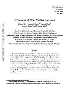
^ m Figure 1. (Left) Macroscopic structure of quantized vortex line in He superfluids. The core radius rc is on the order of the superfluid coherence length in 4 He-II (ξ ∼ 0.1 nm) and 3 He-B (ξ & 10 nm), but in 3 He-A the length scale is the healing length of the dipolar spin-orbit interaction (ξD & 10 µm). (Right) Orbital order parameter texture of the soft core of the double-quantum vortex in 3 He-A in magnetic field. The cones indicate the local direction and rotation of the orbital ˆ n ˆ . The topological winding number order parameter triad of unit vectors ˆl, m, of the ˆl texture is n = 2. The texture is nonaxisymmetric: it is composed of a circular half, or meron, and a hyperbolic meron, each with 2π circulation.
4
He-II and 3 He-B are traditional Landau superfluids in that their superflow is potential, ∇ × vs = 0, unless vortex line defects are present. In 3 He-A, where the phase and the orbital structure (represented by the orbital vector ˆl) of the order parameter are linked together, this condition is no longer strictly satisfied. Instead, the so-called Mermin-Ho relation holds [33]: ~ (3) ǫijk ˆli (∇ˆlj × ∇ˆlk ). 4m3 This implies that rotational superfluid flow can be accomplished via an inhomogeneous order-parameter texture ˆl(r). However, the energy cost of the necessary spatial variations, resulting from the rigidity of the order parameter, gives rise to a finite critical superflow velocity also in this system. At this velocity, vorticity with continuously winding structure of the order parameter orientation is formed so that in most cases no hard vortex core is involved. In the simplest form the structure of an isolated continuous vortex has the following spatial distribution of the orbital ˆl-field: ˆl(ρ, φ) = zˆ cos η(ρ) + ρˆ sin η(ρ) . (4) ∇ × vs =
ˆ are the unit vectors of the cylindrical coordinate system; η(ρ) changes Here zˆ, ρˆ and φ from η(0) = 0 to η(∞) = π. This winding ˆl texture forms the so-called continuous soft core of the vortex [34], since it is in this region where the non-zero vorticity of superfluid velocity is concentrated: � � ~ ˆ , ∇ × vs = ~ sin η ∂η ˆz .(5) vs (ρ, φ) = [1 − cos η(ρ)] φ 2m3 ρ 2m ∂ρ
The circulation of the H superfluid velocity around a contour enclosing the soft-core region is quantized, dr · vs = 2κ, corresponding to the quantization number n = 2. Thus the object described by Eq. (4) is a continuous double-quantum vortex. By
Dynamics of vortices and interfaces in superfluid 3 He
10
following the ˆl field across the cross section of the soft-core texture, it is noted that the ˆl vector goes through all possible orientations on the unit sphere. Such a topology of the vortex cross section in two spatial dimensions is known as a skyrmion. In the magnetic field of the NMR measurements the continuous vortex is deformed and its structure is nonaxisymmetric, see Fig. 1. However, its topology is robust to H deformations, and the circulation remains the same: dr · vs = 2κ. It is important to note that, since even in the soft-core region the order parameter retains its bulk structure, the core size of the continuous 3 He-A vortex is not set by the coherence length ξ & 10 nm of the superfluid state. Instead, the relevant length scale is the three orders of magnitude larger dipolar healing length ξD & 10 µm which originates from the spin-orbit coupling. Using the two halves of the skyrmion texture, the circular and hyperbolic merons (Fig. 1) as basic building blocks, other structures of continuous vorticity can be formed. An example are the various continuous periodic vortex textures in zero or low magnetic field [35, 36]. Another important structure is the vortex sheet [37, 38] which competes for living space with the double-quantum vortex line. A concise lexicon of these various structures can be found in Ref. [39]. The concept of the quantized vortex line dates back to Lars Onsager (1949) [40] and Richard Feynman (1955) [41] who found that the Landau irrotationality requirement ∇ × vs = 0 has to be lifted at singular lines where ∇ × vs 6= 0. In the case of 3 He-A these principles were put to a severe test which they finally survived when, in the context of the work of Mermin and Ho in 1976 [33], Chechetkin (1976) [42] and Anderson and Toulouse (1977) [43] the first example of a continuous vortex texture was proposed. 2.2. Vortex states in rotating superfluid The identification of the vortex structures of superfluid 3 He, and of the phase transitions separating these different structures, is based to a large extent on NMR measurements on a rotating sample. In rotation the vorticity ∇× vs is aligned parallel to the rotation axis Ω and generally forms a regular array over the cross section of the cylindrical sample. This is a particularly simple situation where both the structural and dynamic properties of these vortex structures can be analyzed. The minimum energy configuration in rotation is the state with the equilibrium number of rectilinear vortex lines Neq , which on average mimics solid-body rotation of the superfluid, i.e. hvs i = Ω × r, or h∇ × vs i = 2Ω. Since h∇ × vs i = nκnv , the vortex density in the bulk is nv = 2Ω/(nκ). The formation of a new vortex is associated with an energy barrier that has to be overcome before an elementary vortex loop can be nucleated. At sufficiently low applied flow velocities this is not possible, and metastable states with a vortex number N smaller than Neq can be formed. These consist of a central vortex cluster (Fig. 2), with any number of vortex lines 0 < N ≤ Neq . Within the cluster the rectilinear lines are packed to their equilibrium density nv = 2Ω/(nκ), confined by the counterflow of the normal and superfluid components which circulates around the cluster with the velocity ˆ The first term is the velocity of the normal v = vn − vs = [Ωr − nκN/(2πr)] φ. component, locked to co-rotation with the cylindrical container (with radius R), while the second term arises from the combined persistent superflow of the N rectilinear vortex lines in the central cluster. An extreme case is the Landau state – the vortexfree state with N = 0 and vs = 0 (as expressed in the rest frame of the laboratory).
Dynamics of vortices and interfaces in superfluid 3 He
11
vn-vs
v counterflow region vs(r)=κN/(2πr) solid body rotation vs(r)∼Ωr
vn=Ωr
Rc
vs R r
Figure 2. Schematic representation of a vortex cluster confined by the azimuthally circulating counterflow of the normal and superfluid components to the center of the rotating sample. The areal density of rectilinear singly-quantized vortex lines within the cluster is 2Ω/κ and thus their number in a cluster of radius Rc is N = πR2c 2Ω/κ.
This is the state of maximum kinetic energy in the rotating frame. In many of the rotating experiments described below it is the initial state, the starting point for the measurements. Independently of N , the maximum counterflow velocity is at the cylindrical wall at r = R. This we call the velocity of the externally applied flow or the rotation drive of the cylindrical rotating container. At constant rotation the stationary states are thus the equilibrium vortex state and the various metastable states with a depleted vortex cluster. In an ideal cylinder, which is exactly aligned parallel to the rotation axis, it is possible to have more than the equilibrium number of vortices Neq , owing to a finite annihilation barrier [44]. Experimentally the exact value of Neq is important for calibrating the measuring signals from a state with a well-defined configuration and number of vortices. Transient time-dependent rotating states are created in accelerating or decelerating rotation [45]. In Secs. 4 – 5 we describe measurements where rotation is kept constant and the dynamics evolves from vortex seed loops which have been introduced by external means into initially vortex-free counterflow. 2.3. Critical velocity of vortex formation The lowest critical velocity in a rotating superfluid is that at which the free energy of a rectilinear vortex line first becomes negative in the container frame. The corresponding angular velocity is known as the Feynman critical velocity, Ωc1 = κ/(2πR2 ) ln (R/rc ) [41]. It is analogous to the critical field Hc1 for type II superconductors. For a rotating cylinder with a radius of a few mm, Ωc1 ∼ 10−3 rad/s and is thus very small. However, although at Ω > Ωc1 it becomes energetically favorable to introduce vortices in the
Counterflow velocity at the wall (mm/s)
NMR absorption
Dynamics of vortices and interfaces in superfluid 3 He 0.25 0.20
P = 20.9 bar T ≈ 0.96 Tc H = 15.8 mT
step width ∆Ω = κ 2πR2 calibrates κ
Ωc+ 2
0.15
12 Ωc+ 28 κ 2 2πR
κ 2πR2
0.10
∆Ω = 69 mrad/s ; 26 steps 1 step = 2.65 ± 0.02 mrad/s
2.256
κ = 0.066 mm2/s = h/2m3
2.252 2.248 2.244
vc=Ωc R κ = 5 . 3 . 10 - 3 m m / s 2πR
2.240
1.1
1.15 Rotation velocity Ω (rad/s)
1.2
Figure 3. Measurement of single vortex formation as a function of the applied rotation velocity Ω at high temperatures in 3 He-B [47]. (Top) The vertical axis shows the NMR absorption in the Larmor region of the 3 He-B spectrum. Vortex formation starts with the first step-like increase, but the critical threshold at Ωc is identified from the third step where the critical flow velocity in the bottom plot reaches a more stable value. (Bottom) Counterflow velocity at the cylinder wall v = ΩR − κN/(2πR), where N is the number of steps already formed. The maximum possible value of counterflow for this sample container is defined by the horizontal dashed line, v = vc = Ωc R.
rotating sample, some mechanism for their formation is required. A number of such mechanisms exist, owing to sources both extrinsic and intrinsic to the superfluid itself, each with its characteristic critical velocity. For more discussion see Ref. [46]. Here we only summarize the basic ideas important for the overall picture. In practice, in 3 He-B the lowest critical velocity Ωc , which controls the formation of vortices, is found to depend on the shape and size of the container and the roughness of its surfaces. The simplest and most ideal case is a smooth-walled cylinder which is mounted with its symmetry axis as parallel to the rotation axis as possible. The surface quality is dependent on the choice of material, the fabrication of the seams in the corners, and the cleanliness of the walls. Even residual gases, such as air or water, will condense on the wall during cool down, form small crystallites, and may determine Ωc . In a good sample cylinder of typical radius 2 – 3 mm, Ωc is relatively high, of order 1 – 4 rad/s, so that large vortex-free counterflow can be achieved before the first vortex is formed. In the worst case extrinsic sources govern Ωc . For instance, it can be determined by some pinning site, a piece of dirt, at which a remnant vortex may remain pinned indefinitely. If this site is occupied and Ω is increased to the critical value associated with the site, the pinned remnant loop will start to evolve. In the most favorable case Ωc arises from a combination of extrinsic and intrinsic reasons, if vortex formation takes place at a sharp surface asperity in the form of a pointed spike [47, 46]. At a very sharp spike the local velocity can exceed the average velocity at the wall by one to two orders in magnitude. Thus superfluidity will be broken first at this location when Ω is increased to Ωc , and a small vortex loop is formed [48]. The loop then evolves to a rectilinear vortex line and reduces the
Dynamics of vortices and interfaces in superfluid 3 He
13
counterflow velocity at the cylinder wall to a sub-critical value v = Ωc R − κ/(2πR). If Ω is increased further by external means, vortex formation occurs recurrently at the same site every time when the counterflow reaches the critical value vc = Ωc R. Here vc is therefore the limit for vortex-free flow in this container. An example of such vortex formation in single-quantum events as a function of Ω is illustrated by the staircase pattern in Fig. 3. This measurement has been performed in a container with R = 2 mm [47]. A similar measurement with 4 He-II has been demonstrated only with flow through orifices of sub-micron size [21, 49]. An estimate of the intrinsic critical velocity, and of the energy barrier which inhibits the formation of an elementary vortex loop, can be obtained from the following simple consideration [46]. The barrier is determined by the smallest possible vortex ring. Since the radius of such a ring cannot be smaller than the core radius (of the order of ξ), the energy of the smallest ring can be estimated from Eq. (2) as E ∼ ρs κ2 ξ. This gives E/kB T ∼ (ξ/a)(TF /T ), where we have used ρs ∼ m/a3 for the superfluid density and TF = ~2 /2ma2 kB ∼ 1 K for the degeneracy temperature of the quantum Fermi liquid, with a as the interatomic distance. For 3 He-B we obtain E/kB T > 105 . This should be compared to a similar estimate E/kB T > 1 for 4 He-II, where the core size and the coherence length are ξ ∼ a. How to overcome such an energy barrier [50, 51]? The rate for thermal activation over the barrier is ∝ exp(−E/kB T ), and thus the barrier is practically impenetrable by thermal activation or quantum tunneling [52] at the appropriate temperatures for 3 He superfluids (T ∼ 1 mK) [46, 47]. Both mechanisms become effective only when the local velocity at the asperity reaches a value extremely close to the threshold where the energy barrier disappears, and the hydrodynamic instability of the flow occurs. This occurs at a velocity of order vc ∼ κ/ξ. In 3 He-B, this critical velocity for vortex formation is comparable to the Landau critical velocity for quasiparticle creation – the pair-breaking velocity vpb = ∆/pF ∼ κ/ξ, where ∆ is the superfluid energy gap. In contrast, in 3 He-A the smallest possible vortex loop is of the order of the soft-core radius, the healing length of the spin-orbital coupling ξD & 10 µm. This is several orders of magnitude larger than the coherence length ξ. Consequently, the critical velocity for A-phase vortex formation, vc ∼ κ/ξD , is considerably smaller [46] while the energy barrier is higher than in the B phase. Therefore, in practical experimental conditions neither thermal activation nor quantum tunneling are of importance in 3 He superfluids. Instead, vortex formation takes place when the average counterflow velocity at the wall is increased to the point where the local velocity at the sharpest asperity reaches the critical value, the barrier vanishes, and the process thus becomes an instability. In principle, pair breaking and quasiparticle emission might occur already at a slightly lower velocity than when the barrier actually disappears, and this might finally trigger the hydrodynamic instability, which then results in vortex formation. The process might happen in the following manner: near the asperity the local velocity reaches the pair breaking value, the creation and emission of quasiparticles increases the density of the normal component, and as a result ρs decreases. Due to the conservation of current ρs vs the superfluid velocity then increases, enhancing the radiation of quasiparticles, which increases vs further. The final result from the development of such a hydrodynamic instability will be vortex formation. However, whatever is the real mechanism of the instability generated by the flow in the vicinity of a protuberance, it limits the maximum counterflow velocity that can be achieved in a given sample container. With careful preparation of the surfaces, the critical velocity vc has been raised up to about
Dynamics of vortices and interfaces in superfluid 3 He
14
0.1 – 0.4 vpb in cylinders from fused quartz with R ∼ 3 mm. The situation is quite different in 4 He-II. Although the maximum possible superfluid velocity, the Landau value, is three orders of magnitude higher, the nucleation barrier height is 1 – 10 K and comparable to the ambient temperature of ∼ 1 K. In the flow through sub-micron-size orifices thermal activation has been found to be an important mechanism in vortex nucleation [53, 49] (at the lowest temperatures even quantum tunneling has been argued to exist [54, 55]). In contrast, in applications of bulk volume 4 He-II flow it is assumed that there always exist an abundance of remnant vortex loops pinned to walls [56] which start to expand in low applied flow. In 3 He-B surface pinning is expected to be much less important than in 4 He-II because the vortex core radius is more than two orders of magnitude larger. In the best conditions in a clean quartz cylinder there are no pinned remnant vortices. In such cases no other kind of information about surface pinning exists at present time. However, dynamic remnant vortices are present at low temperatures. When mutual friction dissipation becomes exponentially small, it may take hours for the last vortex to annihilate at the container wall in conditions of zero applied flow. If a remnant vortex loop happens to be around when flow is reapplied, it starts to evolve and may generate any number of new independent vortex loops [57]. In fact, this situation is expected to prevail also in bulk 4 He-II over most of the experimentally accessible temperature range and thus no source with abundant pinned remnant vortices is needed to create large numbers of vortices and turbulent flow. In 3 He-B we thus expect that a genuine intrinsic critical velocity is determined by the most effective instability, since the vortex formation barrier is impenetrable at all temperatures and velocities below an upper limit vc (T, P ). This feature has been utilized to study the different instabilities described in the later sections. The upper limit is a container specific critical velocity (which may change from one cool down to another, depending on the container’s preparation), of which an example is seen in Fig. 3. In such a measurement the criterion for vortex formation is the lowest critical velocity, in other words it is the vortex structure with the lowest vc which is formed. If on the other hand one wants to establish the true equilibrium vortex structure, one has to slowly cool the sample at constant flow velocity below Tc . At Tc critical velocities vanish and the criterion for the selection becomes the lowest energy state. The equivalent of this procedure in superconductivity is known as field cooling. Cooling under rotation has to be used in 3 He-A in order to stabilize and identify the single-quantum vortex (with n = 1) which at low flow velocities has lower energy than the double-quantum vortex which, in turn, has a much lower critical velocity. Again, the large difference in critical velocities of these two vortex structures arises because of their different core structures. As distinct from the doubly quantized vortex, the singly quantized 3 He-A vortex has a hard vortex core with a radius comparable to the superfluid coherence length ξ (which lies hidden and embedded within a three orders of magnitude larger soft core of continuous structure [58]). As a result, its critical velocity vc ∼ κ/ξ is close to the critical velocity for the formation of a Bphase vortex. The formation of the purely continuous texture of a doubly-quantized A-phase vortex does not involve breaking the superfluid state anywhere; it merely requires reorienting the degeneracy variables of the order parameter. That is why the corresponding critical velocity is much smaller, vc ∼ κ/ξD . These theoretical predictions have been tested in numerous different rotating experiments. Such measurements also indicate a wide range of variation in the
Dynamics of vortices and interfaces in superfluid 3 He
15
observed A-phase critical velocities, proving that they depend on the prehistory of sample preparation and thus on the quality of the global order parameter texture [59, 60]. Entry into the texture at unusually low critical velocity is provided by such regions where the spin-orbit coupling is not minimized, if they extend to the cylindrical boundary. Thus the largest reductions in critical velocity are observed in the presence of different types of planar domain-wall-like defects in the A-phase order-parameter field, which are called solitons [61]. If the plane of the soliton is oriented parallel to the rotation axis (called a splay soliton), then the critical velocity approaches zero, although it apparently always remains finite, and all vortex quanta will enter from along one of the two connection lines of the soliton sheet with the cylinder wall. This means that the emerging vortices are not lines but a periodic chain of circular and hyperbolic vortex quanta stacked within a soliton sheet (Fig. 1). This structure is called a vortex sheet [37]. It has the lowest critical velocity of all A-phase vortex structures and also the fastest dynamic response [62]. Numerical calculations of the flow instability of various different one-dimensional initial textures [63] show that semiquantitative agreement with the measured variation exists. A further peculiarity of A-phase vortex textures is the existence of remnant vorticity in the form of vortex lines pinned in soliton sheets in the bulk liquid [64]. The large difference between the critical velocities for the formation of a doubly quantized A-phase vortex and a singly quantized B-phase vortex makes it possible to create different metastable flow states in a rotating two-phase sample. 2.4. Vortices and AB interface in rotation With two 3 He superfluids which belong to the same order parameter manifold it becomes possible to construct a unique situation which does not exist in other known coherent quantum systems. With a profiled magnetic-field distribution it is possible to achieve the coexistence of 3 He-A and 3 He-B, and to stabilize an AB phase boundary in the sample. What happens to such a superfluid two-phase sample in rotation? The substantial mismatch in the vortex properties of the two phases – their critical velocity, quantization of circulation, and vortex structure – raises the question: How are the vortices going to behave at the AB interface? In 3 He-A the critical velocity is low, while in 3 He-B it is an order of magnitude higher. This means that the A phase tends to be filled with essentially the equilibrium number of double-quantum vortex lines, while in the B phase there would at least initially be no vortices. Is such a situation stable, how is it going to evolve, and how are the single-quantum vortices of 3 He-B going to fit in this picture if they emerge later at higher velocities? The left-hand side of Fig. 4 depicts the situation where the two-phase system is brought into rotation at constant temperature. When the rotation is started, Aphase double-quantum vortices are created at low critical velocity while no vortices are formed in the B phase. This expectation, confirmed by measurement [65], means that the A-phase vorticity is not able to cross the AB interface and is accumulated on the A-phase side of the interface such that it coats the interface with a dense vortex layer. The layer is made up of a continuous texture of vorticity [66] and sustains the tangential discontinuity in the flow velocities of the superfluid fractions on the different sides of the AB interface. Thus we have constructed a metastable state in which the two superfluids slide with respect to each other with a large shear-flow discontinuity, since the superfluid fraction in the A phase rotates solid-body-like while that in the B phase remains stationary in the inertial frame.
Dynamics of vortices and interfaces in superfluid 3 He
0
16
ΩR
3He-A with double-quantum vortices
0
ΩR
v
v boojums at AB interface 3He-A with double-quantum vortices
n=2
dissociation to n = 1 merons
vs ≈ vn
n=2
bending layer
AB interface
vs
vortex layer consisting of n = 1 merons
vn
n=1 equilibrium AB interface in rotation
vortex-free 3He-B
z
3He-B with single-quantum vortices
z
Figure 4. Sketches of the AB interface in rotation. Left: In the A phase double-quantum vortex lines are formed at low rotation and we may assume it to be approximately in the equilibrium vortex state. At the AB interface the double-quantum vortices curve over to the cylinder wall and cover the AB interface as a vortex layer. This layer supports the discontinuity in the tangential velocities of the superfluid fractions at the AB interface. The width of the AB interface is on the order of the superfluid coherence length ξ while that of the vortex layer is three orders of magnitude larger, namely the dipolar healing length ξD . Thus in this metastable state below the critical velocity the continuous Aphase vorticity does not penetrate through the AB interface, but gives rise to the unusual axial distribution in the flow velocities of the normal and superfluid components, vn (r) = Ωr and vs (r), as shown on the right for r = R. Right: In equilibrium rotation, an A-phase double-quantum vortex with winding number n = 2, dissociates at the AB interface into its 2π constituents, the circular and hyperbolic merons, each with n = 1. Each meron gives rise to a singular point defect, a boojum, on the AB interface. The boojum is required as a termination point of a singular 2π (n = 1) B-phase vortex. Thus in the equilibrium state the continuous vorticity crosses the AB interface, transforming to singular vorticity. However, neither point or line singularities are easily created in superfluid 3 He and therefore the vortex crossing takes place in a Kelvin-Helmholtz instability event.
The minimum-energy state is shown on the right in Fig. 4. Here the vorticity is conserved on crossing the interface and both phases contain the equilibrium number of vortices at any given angular velocity of rotation. Accordingly, the number of doublequantum vortices in the A phase is one half of the number of singular singly-quantized B-phase vortices. On approaching the interface, the continuous A-phase vortex splits into its two 2π constituents or merons. Each of the merons ends in a boojum on the AB interface. The boojum is a point-like topological singularity of the orbital ˆl vector at the AB interface, the termination point of a singular B-phase vortex on the AB interface. In practice singularities are not easily created in superfluid 3 He: like in the case of vortices the energy barrier is too high compared to ambient temperature (typically by 6 – 9 orders of magnitude). Therefore the equilibrium state at the AB interface is not obtained by increasing rotation at constant temperature and pressure [65]. Nor is it formed by cooling through Tc at constant rotation and pressure, which is the usual method to create the equilibrium vortex state below a second-order phase transition.
Dynamics of vortices and interfaces in superfluid 3 He
17
The reason is that here the first order A→B transition also has to be traversed, to form the AB interface within the sample [67, 68]. The closest approximation to the equilibrium state is obtained by starting with the equilibrium number of B-phase vortices in a single-phase sample at high rotation, with the barrier field at zero or at sufficiently low value. Next the barrier field is swept up (at constant Ω, T , and P ), until A phase and the AB interface is formed. In this case the equilibrium superfluid circulation is already trapped in the sample and cannot all escape. Finally, by reducing rotation to the point where B-phase vortices start to annihilate, one has reached the equilibrium vortex state. In contrast, if one simply starts increasing rotation of a two-phase sample with an AB interface, very different behavior is observed because of the energy barriers preventing the nucleation of point and line singularities. This is one of the ways to demonstrate the superfluid Kelvin-Helmholtz instability, where the AB interface becomes unstable in the presence of an excessively large counterflow velocity which is oriented parallel to the AB interface (Sec. 3). A complex chain of events is then started in which also vortices escape across the AB interface from the A to the B-phase side. 2.5. Vortex dynamics and mutual friction In 3 He-B and 4 He-II, in the absence of vorticity, the superflow is potential and the superflow velocity vs = ∇Φ is expressed in terms of the “flow potential” which is proportional to the phase of the superfluid wave function, Φ = (κ/2π)ϕ. The superflow velocity vs obeys the Euler equation [69]: ∂vs + ∇˜ µ = 0, (6) ∂t where µ ˜ = µ + vs2 /2 and µ is the chemical potential. When quantized vortices (or continuous vorticity in 3 He-A) are present, the superfluid velocity is no longer potential. The motion of a vortex leads to a phase-slip effect and modifies the r.h.s. of Eq. (6). Vortex lines form a part of the superfluid component, but the normal component influences their movement through mutual friction which arises from the scattering of normal excitations from the vortex cores. In the zero-temperature limit, where the normal excitations vanish, the motion of a vortex line is governed by the Magnus force only, so that the vortex velocity coincides with the local superfluid velocity at the position of the vortex element. At non-zero temperatures the friction between the vortex and the normal component – the so-called mutual friction – causes a drag force on the vortex line and, as a result, the velocity vL = drL /dt of a vortex segment in the flow deviates from vs . In the presence of vortices, the flow potential is not uniquely defined along the contours encircling the singular vortex lines. If the vortices do not overlap, the flow potential can be written as Φ=
N X
β=1
Φβ (r − rβ , t) .
Here rβ (sβ ) are the coordinates of singular lines specified by a parameter sβ . If the positions of these lines also depend on time, rβ = rβ (t), the time derivative of the
Dynamics of vortices and interfaces in superfluid 3 He
18
superflow velocity becomes � � ∂ ∂ ′ Φ X ∂rβ ∂vs = ∇Φ = ∇ − · ∇ ∇Φβ ∂t ∂t ∂t ∂t β ′ X X ∂Φ − (vβ · ∇Φβ ) + [vβ × ωβ ] . = ∇ ∂t β
β
Here ∂ ′ /∂t is the derivative only of the explicit t dependence of Φ and we put vβ = ∂rβ /∂t. The vorticity of a single vortex is ωβ = curl vs β = curl ∇Φβ . 3
4
In He-B and He-II the vorticity from singular vortex lines is expressed as Z ωβ = κβ δ (r − rβ ) drβ .
(7)
Here rβ is the coordinate of the β-th vortex line and δ (r − rβ ) is the three-dimensional δ-function, drβ = ˆsβ dsβ , ˆsβ is the unit vector in the direction of the vortex line at the point rβ , and dsβ is the arc length of the vortex line. The circulation of each vortex κβ = nβ κ may have nβ circulation quanta κ. Since the derivative ∂Φ ∂′Φ X = − (vβ · ∇Φβ ) ∂t ∂t β
is usually defined as the “superfluid chemical potential” µs = −∂Φ/∂t we have X ∂vs + ∇µs = vβ × ωβ . ∂t
(8)
β
One can write here µs = µ ˜ +µ ˜s , where µ ˜s = µs − µ ˜ is the deviation of the superfluid chemical potential from the total chemical potential of the fluid, which is the counterpart of the gauge-invariant scalar potential in the theory of nonstationary superconductivity [70]. In equilibrium µ ˜s = 0, so that µs = µ ˜, which in fact is the famous Josephson relation. The velocity of each vortex is determined up to its component perpendicular to the vortex line [27]: vβ = ˆsβ × (vs × ˆsβ ) + αˆsβ × (vn − vs ) − α′ ˆsβ × [ˆsβ × (vn − vs )] (9)
Here α(T, P ) > 0 and α′ (T, P ) < 1 are the temperature and pressure dependent dissipative and reactive mutual-friction parameters. Inserting Eq. (9) into Eq. (8) we find X X Z vβ × ωβ = κβ δ(r − rβ ) dsβ [ˆsβ × [ˆsβ × (ˆsβ × vs )]] β
β
′
+α
X
−α
β
δ(r − rβ ) dsβ [ˆsβ × [ˆsβ × (ˆsβ × (vn − vs ))]]
Z
δ (r − rβ ) dsβ [ˆsβ × [ˆsβ × (vn − vs )]] .
κβ
β
X
Z
κβ
Dynamics of vortices and interfaces in superfluid 3 He The first line gives X
κβ
β
=− where
Z
X
ωs =
19
δ(r − rβ ) dsβ [ˆsβ × [ˆsβ × (ˆsβ × vs )]] κβ
β
X
Z
δ(r − rβ ) dsβ [ˆsβ × vs ] = vs × ωs
(10)
ωβ
β
is the total vorticity of the superfluid. The second line can be transformed in the same way. As a result, ∂vs + ∇˜ µ = vs × ωs + fmf . (11) ∂t Here fmf is the mutual-friction force [71] X Z fmf = − α κβ δ (r − rβ ) drβ × [ˆsβ × (vn − vs )] β
′
+ α [(vn − vs ) × ωs ]
(12)
exerted by the normal component on a unit mass of superfluid via the vortex lines. The first term in fmf is the viscous component, with a negative projection on the relative velocity vs − vn , X Z fmf ·(vs − vn ) = −(vs − vn )2 α κβ δ (r − rβ ) [1 − cos2 γβ ] dsβ .(13) β
Here γβ is the angle between sβ and vs − vn . Without mutual friction force, Eq. (11) coincides with the Euler equation of the classical hydrodynamics of an ideal inviscid fluid ∂v + ∇˜ µ = v × ω. (14) ∂t In what follows we consider the case where all vortices have the same circulation with n = 1. For 3 He-B, the mutual-friction parameters were measured in Refs. [72, 73]. This remarkable hydrodynamic measurement was performed by examining capacitively changes in antisymmetrically driven normal modes of a thin membrane which lies in the plane perpendicular to the rotation axis. As will be seen in Sec. 5 (Fig. 26), these results agree with later measurements on the longitudinal propagation velocity of vortices in the rotating cylinder which also yield the dissipative parameter α. These experimental data agree with calculations of the parameter values in Refs. [8, 9, 10] (for a theory review see [11]). The mutual friction parameters are discussed also in terms of the chiral anomaly and the Callan-Harvey effect in relativistic quantum field theory in Ref. [4]. Both α and α′ vanish at T = 0. With increasing temperature the dissipative mutual-friction parameter α increases so that above 0.6 Tc all dynamic processes are heavily overdamped in 3 He-B. In 3 He-A α is expected to be in the overdamped regime at all currently accessible temperatures [9, 72, 74]. In contrast, in 4 He-II α is much smaller at all experimentally relevant temperatures, as seen in Fig. 5. The difference in the magnitudes of the mutual-friction parameters for superfluid 3 He and 4 He is
Dynamics of vortices and interfaces in superfluid 3 He 3He-B (29 bar)
20 He-II
α
1
α
1
0.1
0.1
0.01
0.01 10
1
1
(1−α’)/α
(1−α’)/α
10
,
0.1 0.3
T.D.C. Bevan et al. J. Low. Temp. Phys, 109, 1997. 0.4
0.5
0.6
T/Tc
0.7
0.8
R.J. Donnelly and C.F. Barenghi J. Phys.Chem. Ref. Data, 27, 1998. 1.4
1.6
1.8
2
0.1 2.2
T (K)
Figure 5. Mutual friction covers a different range of values in 3 He-B (left column of panels) and 4 He-II (right column). The top row of panels shows the dissipative mutual friction coefficient α(T ) and the bottom row the dynamic parameter q −1 = (1 − α′ )/α. A transition in vortex dynamics is expected at q ∼ 1. The data for 3 He-B is from Refs. [72, 73] and for 4 He-II from Ref. [75].
so striking that the usual picture of 4 He-II vortices moving with the superflow fails for 3 He vortices which move across the flow in most of the accessible temperature range. In this respect, motion of vortices in 3 He resembles that in most of type-II superconductors where they also move perpendicular to the flow with practically no measurable Hall angle [11]. Since the equation of motion (9) for the trajectory of a vortex only depends on the two parameters α and α′ , its solutions can be classified in terms of the dynamic parameter q defined as α . (15) q≡ 1 − α′ This parameter has already been introduced in Section 1.1. According to both the theoretical predictions [10] and the experimental data for 3 He-B the parameter q depends exponentially on temperature in the low-temperature limit. The lower row of panels in Fig. 5 shows the inverse q −1 = (1 − α′ )/α for 3 He-B and 4 He-II. In superfluid dynamics q acquires an important function: it characterizes the relative influence of dissipation and 1/q plays the role of the Reynolds number (Sec. 4.3). A change in the characteristic solutions and a corresponding transition in the dynamics can be expected in the regime q ∼ 1: this is located in the middle of the temperature range for 3 He-B, but only a few µK below Tλ for 4 He-II. It is instructive to inspect some solutions of Eq. (9), as sketched in Fig. 6, for an ideal rotating cylinder where the rotation and cylinder axes coincide. We assume the
Dynamics of vortices and interfaces in superfluid 3 He
21
experimentally important situation where the applied counterflow velocity dominates, i.e. we set in Eq. (9) vn = Ω × r and vs ≈ 0, and consider a large enough q so that the vortex dynamics is regular (instead of turbulent, see Sec. 4). The simplest case (a) is a rectilinear vortex line parallel to the rotation axis which is released in the flow from the cylinder wall. This might correspond to the situation in which a double-quantum vortex forms in 3 He-A when the cylinder is filled with a perfect global texture. In the cylindrically symmetric flow geometry the vortex will retain its rectilinear shape while it travels inward along a spiral which finally places the line in its equilibrium position along the axis of the cylinder. Another important case is (b) a vortex with a free end expanding in a long cylinder. The free end terminates perpendicular on the cylinder wall and describes a regular helix on the wall during its expanding motion. If we neglect the influence from its own curvature on the motion, then the curved section of the vortex remains within the same radial plane which rotates at the angular velocity (1 − α′ )Ω around the cylinder axis, when viewed from the rotating frame. The trailing section of the vortex becomes aligned along the central axis and remains at rest there. An immediate extension of this example is case (d) where the vortex expands in a cylinder in the presence of a pre-existing cental vortex cluster. The rectilinear trailing end of the vortex becomes now part of the vortex cluster and is incorporated as one of the vortices in the peripheral circle of lines. This section would prefer to be stationary in the rotating frame, it resides in a region of the sample cross section where the average counterflow velocity vanishes, and therefore it moves only with difficulty from one lattice site to the next in the outermost ring of vortex lines. The free end, on the other hand, expands along a spiral trajectory and leaves behind a helix which cannot relax instantaneously. To explore the hydrodynamic transition between regular and turbulent vortex dynamics at q ∼ 1, we can ask the following question: how is the dynamic equation (11) modified for superfluids in the continuous limit, after averaging locally over vortex lines? This can be done even for tangled vortex states, if the lines are locally sufficiently parallel and their radius of curvature is much larger than the vortex core diameter. This would be the case, for instance, for rotating states with transient time-dependent disorder, since the rotating flow would rapidly polarize the component parallel to the rotation axis while the order in the transverse plane would be restored only later. In this case the averaging over nearby vortices on the r.h.s. of Eq. (11) gives ∂vs ˆ s × [ωs × (vs − vn )] .(16) + ∇˜ µ = vs × ωs − α′ (vs − vn ) × ωs + α ω ∂t This result is known as the coarse-grained hydrodynamic equation for the superflow velocity [76]. It will later be used to develop an analogous superfluid interpretation to the transition to turbulence, as can be derived in viscous hydrodynamics from the Navier-Stokes equation [25]. 2.6. Kelvin-wave instability of vortex lines A quantized vortex can support helical Kelvin waves which become important in turbulent vortex dynamics. The Kelvin waves may lead to an instability which generally develops at large flows. This instability can result in an increase in the number of individual vortex lines under an applied flow if the mutual friction is sufficiently small. It is the first step in the process by which more vortices can be generated from one or a few existing vortices so that bulk volume turbulence can switch on. The evolution towards the instability starts when a vortex becomes sufficiently
Dynamics of vortices and interfaces in superfluid 3 He
22
αΩR (1−α′)ΩR
αΩr
(1−α′)ΩR
(1−α′)Ωr
(1−α′)ΩR
αΩR
a) rectilinear vortex
b) curved end of single vortex
αΩR
c) half ring on cylinder wall
(1−α′)(Ω−Ωv)R α(Ω−Ωv)R
d) curved end outside vortex cluster
Figure 6. Sketches of vortex trajectories in an ideal rotating cylindrical superfluid sample, as viewed in the rotating frame. (a) A rectilinear vortex, which is released in the flow from the cylinder wall, travels along a spiral to its equilibrium location, to become aligned along the center axis of the cylinder. (b) In a long cylinder the propagating end of the vortex describes a spiral trajectory on the cylinder wall while it expands into the vortex-free section of the cylinder. The trailing end is aligned along the central axis, the equilibrium location for the vortex. (c) An elementary vortex usually forms as a half ring on the cylinder wall. It expands both axially and radially. Neglecting the contribution from its selfinduced velocity, the half ring positions itself perpendicular to the azimuthally circulating applied flow and remains during its expansion inside a radial plane which rotates around the cylinder axis with angular velocity (1−α′ )Ω with respect to the cylinder walls. (d) If a central vortex cluster already exists in the cylinder (with N = πR2c 2Ω/κ rectilinear vortex lines), then the spiralling motion leaves behind a helically wound vortex. At low temperatures, when the axial motion is slow, a tightly wound helix forms around the cluster. The end section of this vortex, where it approaches the cylindrical wall, is most likely to suffer the Kelvinwave instability. Here the applied flow velocity is large and the vortex is partly aligned azimuthally along the applied flow.
aligned along the applied flow. A vortex line oriented parallel to the external flow is an unstable configuration, as demonstrated by Donnelly et al. by applying a thermal counterflow current parallel to rectilinear vortex lines in rotating 4 He-II [77]. Above a critical axial flow velocity rectilinear vortices became unstable and formed a turbulent tangle with varying axial polarization, depending on the axial counterflow velocity. The phenomenon was explained by Glaberson et al. [78, 79] in terms of the Kelvinwave instability and was later reproduced also numerically by Tsubota et al. [80]. Consider small transverse deformations to an isolated vortex line, oriented along the z axis, in externally applied counterflow v = v ˆz parallel to it. Parametrizing the position vector of an arbitrary element on the deformed vortex as r(z, t) = ζ(z, t)ˆ x + η(z, t)ˆ y + zˆz,
(17)
we can write the unit tangent of the line as ˆs(z) ≈ (∂ζ/∂z)ˆ x + (∂η/∂z)ˆ y + zˆ (to linear order in the small quantities ζ, η). The vortex curvature also gives rise to a self-induced contribution to the superfluid velocity at the vortex line. In the local approximation [27, 76] � 2 � ∂ η ∂2ζ ∂2r ∂r i ˆ+ 2 y ˆ , ≈κ ˜ − 2 x (18) × vs = κ ˜ ∂z ∂z 2 ∂z ∂z where κ ˜ = (κ/4π) ln(2π/krc ). Inserting these to the equation of motion for the vortex line, Eq. (9), we find � 2 � � � 2 ∂ζ ∂ η ∂ ζ ∂η ∂ζ ∂2η ′ ˜ 2 −v +α κ , ˜ 2 +v = −κ ˜ 2 +α κ ∂t ∂z ∂z ∂z ∂z ∂z
Dynamics of vortices and interfaces in superfluid 3 He
23
� 2 � � � 2 ∂ ζ ∂ η ∂ζ ∂η ∂2ζ ∂η ˜ 2 +v − α′ κ . ˜ 2 −v =κ ˜ 2 +α κ ∂t ∂z ∂z ∂z ∂z ∂z
(19)
ω = (1 − α′ )˜ κk 2 − α′ kv − iα(˜ κk 2 − kv).
(20)
The dispersion relation for wavelike disturbances ∝ exp[−i(ωt − kz)], i.e. Kelvin waves, can be found as With vanishing counterflow, v = 0, the dispersion relation simplifies to [81] ω=κ ˜k 2 (1 − α′ − iα).
(21) ′
Here we again encounter the dynamic parameter q = α/(1 − α ) already introduced in Eq. (15) as the ratio of the imaginary and real parts of the dispersion [82]. The waves are always damped but at high temperatures, where q > 1, the waves are overdamped and do not propagate. On the other hand, in the presence of externally applied flow the long-wavelength modes with k < v/˜ κ have Im(ω) > 0, and exhibit exponential growth. In other words, if an evolving vortex configuration at some time has long enough vortex-line sections oriented parallel to external flow, these will become unstable to exponentially growing helical deformations. The expanding waves can then undergo reconnections, either with the walls of the container or with other vortex lines. This leads to a growing number and density of vortices and, ultimately, if q is small enough, to the onset of turbulence, as discussed in Sec. 4.6. 3. Kelvin-Helmholtz instability in superfluids 3.1. Introduction The Kelvin-Helmholtz shear flow instability is a well-known phenomenon of classical hydrodynamics which was first discussed by Lord Kelvin already in the 1860’s. It occurs at the interface between two fluid layers which are in relative motion with respect to each other. For instance, at low differential flow velocity the interface between two stratified layers of different salinity or temperature is smooth in the ocean, but at some critical velocity waves are formed on the interface. Similarly, ripples do not form on the water surface on a lake at infinitesimal wind velocities, but form at some finite critical value. The Kelvin-Helmholtz instability is thus a common phenomenon in nature around us. The condition for instability is derived in many textbooks on hydrodynamics [83, 84] in the limit of inviscid and incompressible fluids. In superfluids it was first observed at the rotating AB interface [65]. The AB interface instability occurs between the two 3 He superfluids, 3 He-A and 3 He-B, when their superfluid fractions move with respect to the normal component tangential to the AB interface (Fig. 4 left). This initial state is dissipationless while the state after the instability is not, as surface waves or ripplons form on the interface and their motion is highly damped. In conventional liquids and gases the mathematical description of the interfacial instability is inevitably only approximate: if viscosity is neglected, the initial nondissipative states of the two liquid or gas layers sliding with respect to each other are not exact. The question then arises not only about the true value of the critical velocity, but more generally about the existence and nature of the instability. Superfluids are the only laboratory examples of cases where viscosity is totally absent, and the mathematical description of the instability can be presented analytically in a simple form. The initial state of the AB interface with different
Dynamics of vortices and interfaces in superfluid 3 He
24
tangential superflow velocities across the interface is in nondissipative thermodynamic equilibrium, until the critical velocity of the hydrodynamic instability is reached. As a result – contrary to viscous normal fluids – the instability threshold is well defined. Experimentally it is manifested by the sudden formation of vortices in the initially vortex-free 3 He-B phase (Fig. 4 right) at a rotation velocity at which no vortices would yet be formed without the presence of the AB interface. 3.2. Kelvin-Helmholtz instability in classical hydrodynamics The Kelvin–Helmholtz (KH) instability is one of the many interfacial instabilities in the hydrodynamics of liquids, gases, charged plasma, and even granular materials. It refers to the dynamic instability of an interface with discontinuous tangential flow velocities and can loosely be defined as the instability of a vortex sheet. Many natural phenomena have been attributed to this instability. The most familiar ones are the generation of capillary waves on the surface of water, first analyzed by Lord Kelvin [85], and the flapping of sails and flags, first discussed by Lord Rayleigh [86]. Many of the leading ideas in the theory of interfacial instabilities in hydrodynamics were originally inspired by considerations about ideal inviscid flow. The corrugation instability of the interface between two immiscible ideal liquids, with different mass densities ρ1 and ρ2 , occurs in the gravitational field at the critical differential flow velocity [85] (U1 − U2 )4 = 4σg
|ρ1 − ρ2 |(ρ1 + ρ2 )2 , ρ21 ρ22
(22)
where σ is the surface tension of the interface, and g is the gravitational acceleration. To separate the gravitational and inertial properties of the liquids, we rewrite the threshold velocity in the form √ ρ1 ρ2 (23) (U1 − U2 )2 = 2 σF . ρ1 + ρ2 Here F is the external field stabilizing the position of the interface, which in the case of a gravitational field is F = g(ρ1 − ρ2 ) ,
(24)
but can in general originate from some other source. The surface mode of ripplons, or capillary waves, which is first excited has the wave number corresponding to the inverse ‘capillary length’ p k0 = F/σ . (25)
However, ordinary fluids are not ideal and the correspondence between this theory and experiment is not satisfactory. One reason for this is that the initial state cannot be properly prepared – the shear-flow discontinuity is never an equilibrium state in a viscous fluid, since it is not a solution of the Navier-Stokes equation. As usual in hydrodynamics, it is not apparent whether the notion of ‘instability’ can be properly extended from the idealized inviscid model to the proper zero viscosity limit of the Navier-Stokes equation and further to the case of finite viscosity [87].
Dynamics of vortices and interfaces in superfluid 3 He
25
3.3. Experimental setup The superfluid Kelvin-Helmholtz experiments reported in Ref. [65] were conducted in a rotating nuclear demagnetization cryostat in which the liquid 3 He sample can be cooled below 0.2 Tc in rotation up to 4 rad/s. A schematic illustration of the sample setup is shown in Fig. 7. The sample is contained in a fused quartz tube of R = 3 mm radius. An aperture of 0.5 – 0.75 mm diameter in the bottom end plate restricts the flow of vortices into the sample from the heat exchanger volume below. The quality of the sample-tube surface is of great importance, since any larger surface defects serve as nucleation and pinning sites. Before use the container is treated with a HF solution, to etch away sharp protuberances, and then cleaned with solvents. The same quartz tube may display sizable variation in critical velocity and vortex formation properties depending on how it is cleaned between experiments, indicating that dust particles, dirt, frozen gas, etc. serve as nucleation and pinning sites. Most measurements were performed using a sample tube which allowed vortex-free rotation up to the maximum rotation velocity of the cryostat. Two independent continuous-wave NMR spectrometers are used for monitoring the sample. Their detector coils are located close to both ends of the sample volume. In these regions of the sample a low magnetic field is needed for NMR polarization which has to be as homogeneous as possible. Therefore three separate superconducting solenoidal magnets with compensation sections, all with their fields oriented along the rotation axis, are needed in the experiment. Two magnets are required for the homogeneous NMR fields and one as a ”barrier magnet” around the central section of the tube for stabilizing 3 He-A. The barrier magnet provides fields up to 0.6 T which is sufficient to stabilize the A phase at all temperatures and pressures. In the inhomogeneous barrier field H(z) the equilibrium position z0 of the AB interface is determined by the equation H(z0 ) = HAB (T ), where HAB (T ) is the first-order phase transition line between the A and B phases in the (H, T ) plane (Fig. 8 left). The two superfluids, 3 He-A and 3 He-B, have very different magnetic properties, as seen in the phase diagram on the left of Fig. 8. In the region where H > HAB (T ) the A-phase has lower magnetic energy, while in the neighboring region H < HAB (T ) the B-phase is favored. Thus the gradient in the magnetic energy densities of the two liquids provides a restoring force F on the AB interface, � 1 � (26) F = ∇ (χA − χB )H 2 . 2 Here χA > χB are the magnetic susceptibilities of the A and B phases, respectively. Accordingly, this ∇H dependent restoring force on the AB interface has to be used instead of gravity in the KH instability condition. Various configurations of A and B phases can be stabilized and trapped in the sample tube. (i) At zero or low barrier fields the B phase might occupy the whole sample volume. In this all-B configuration the two spectrometers probe the same volume. The time difference between the two NMR readings can then be used to study the propagation of vortices along the column. (ii) At barrier fields above HAB (T, P ), the equilibrium transition field between the A and B phases, the A phase is stabilized in the center of the barrier magnet. In this BAB configuration the top and bottom sections of the sample are disconnected: vortex lines generated in one of the B-phase sections do not pass to the other across the A phase region. (iii) At pressures above 21 bar, 3 He-A is stable also at zero magnetic field from Tc down to TAB (P ). At high temperatures the entire sample volume is then filled with A phase (all-A
Dynamics of vortices and interfaces in superfluid 3 He
26
6 mm 5
top NMR pick-up coil H0 = 30 mT f0 = 962 kHz
4 3
B
z (cm)
2 1 0
A
magnetically stabilized A phase
-1
-3
d
-2
-4
9 mm
-5 -1
0 1 r (cm)
bottom NMR pick-up coil H0 = 21 mT f0 = 682 kHz Bottom plate with orifice
Figure 7. Two-phase superfluid 3 He sample for measurements on the KelvinHelmholtz instability. The sample volume is 6 mm in diameter and 11 cm long. A small orifice of 0.5 – 0.75 mm in diameter in the center of the bottom end plate separates the sample from the rest of the liquid 3 He volume. The 3 He below the orifice is needed to establish thermal contact to the refrigerator. NMR pick-up coils are located at both ends of the sample tube. They are circular coils with their symmetry axis transverse to the tube axis. Two solenoidal superconducting magnets provide the homogeneous axially oriented polarizing fields for NMR. A third barrier magnet creates the field to stabilize 3 He-A in the center section of the long sample. Two examples of the A phase region (shaded) are shown at 0.55 Tc : at the current of Ib = 8 A in the barrier solenoid the A phase extends further in the column and the two AB boundaries are almost flat, while at Ib = 4 A the A phase region is short and the AB boundaries are concave.
configuration). When the temperature is lowered somewhat below the equilibrium A→B transition, B phase nucleates in the heat-exchanger volume and expands into the lower section of the sample (at about 0.75 Tc). If the barrier field is sufficiently high to stabilize the A phase, the advancement of the B phase is stopped by the stable A phase and an AB interface is formed. Since the A phase in the top section can supercool quite substantially [89], the sample remains in the BA configuration (Fig. 8 right). Thus the barrier field isolates the top from an A→B transition in the lower section. Eventually, at a low enough temperature, B phase also forms independently at the top. Since the ultimate supercooling of 3 He-A depends on the surface properties, the A→B transition also serves as a measure of the quality of the quartz walls. At best the top was supercooled to 0.52 Tc at 29 bar (when the equilibrium transition is at TAB = 0.85 Tc). The BA configuration was most important in the early stages of measurements on the AB interface instability, since the top spectrometer is then recording the vortex number in the A phase and the bottom spectrometer in the B
Dynamics of vortices and interfaces in superfluid 3 He
27
P = 29 bar 0.6
0 0
z0
0
-|z0|
B phase
0.5
1
2 1.5 T (mK)
2.5
3
HAB
0.1
stable A phase (true vacuum)
HAB(T)
0.2
z (mm)
0.3
supercooled A phase (false vacuum)
Normal phase
H (Tesla)
0.4
NMR pick-up
45
A phase
0.5
-45 0
0.2
stable B phase (true vacuum) H (Tesla) 0.4
Figure 8. Magnetic stabilization of 3 He-A in the experimental setup of Fig. 7 [65]. (Right) Sample container and the axially oriented magnetic field distribution along the sample in the BA configuration (with current Ib = 4.0 A in barrier magnet). The barrier field maintains A phase in stable state in the section in the middle of the sample, where H > HAB (T ). In the top and bottom sections only the NMR polarization field is applied and H < HAB (T ). In the top A phase may persist in meta-stable state (see text for explanation). One AB interface exists here at the lower location H(−|z0 |) = HAB (T ), where z = −|z0 | is the average axial location of the interface. When the temperature T or the current Ib is varied, changes occur in both z0 (T, Ib ) and in the field gradient ∇H in which the interface resides. The restoring force acting on the AB interface in Eq. (26) depends on the field gradient ∇H and therefore on the field profile of the barrier magnet. (Left) Magnetic phase diagram in the (H, T ) plane, where HAB (T ) marks the first-order phase transition line between A and B phases (at P = 29.0 bar pressure) [88]. The upper plane at z0 (T, Ib ) separates the section in the middle, where 3 He-A is the true vacuum state, from the section in the top, where 3 He-A is the false vacuum. The false vacuum persists down to a container dependent minimum temperature.
phase. To understand what happens in the two-phase sample when rotation is started, and to correlate in real time the events on both sides of the AB interface, simultaneous recordings of vortex numbers in both phases are needed. It turned out that in rotation 3 He-A is in solid-body-like rotational flow, practically locked to co-rotation with the container, owing to its low critical velocity of vortex formation. In contrast, in 3 He-B the superfluid component is in the vortex-free Landau state and stationary in the laboratory frame. This nondissipative initial state becomes possible through the formation of an A-phase vortex layer which covers the AB interface and provides the discontinuity in the tangential flow velocities (Fig. 4 left). The tangential discontinuity is ideal – there is no viscosity in the motion of the two superfluids so that this state can persist for ever. If the rotation velocity is then incrementally increased to the critical value, the Kelvin-Helmholtz instability occurs and some vortices penetrate across the AB interface into the vortex-free B phase (Fig. 4 right). The first time, when this happens in increasing rotation, is called the critical rotation velocity Ωc (T, Ib ). If rotation is increased further, then the instability will occur repeatedly every time when the counterflow velocity close to the cylinder wall reaches the critical value. In each case, the signal for the instability is the appearance of new vortices in the B-phase section. One might think that by substituting the interfacial restoring force F (26) into
Dynamics of vortices and interfaces in superfluid 3 He
28
Eq. (23), and using the superfluid densities of the A and B phases instead of the total density, the critical velocity for the KH instability of the AB interface could be obtained. However, it turns out that a proper extension of the KH instability to superfluids incorporates the criterion in Eq. (23) only as a particular limiting case, namely when T → 0, while in general the physics of the instability is rather different from the ideal inviscid model. A different but well-determined criterion is obtained for the instability condition in terms of the velocities and densities of the superfluid fractions. This criterion is also formulated in the absence of viscosity, as one would expect in a perfect superfluid environment. Therefore the tangential discontinuity at the interface between 3 He-A and 3 He-B below the instability is a stable state. 3.4. Modification of Kelvin-Helmholtz instability in superfluids The criterion for the KH instability of ideal fluids in Eq. (23) depends only on the relative velocity across the interface. In practice there always exists a preferred reference frame imposed by the environment. In the superfluid case this is the frame fixed to the container. At T 6= 0 the normal component provides the coupling to the reference frame: in the state of thermodynamic equilibrium the normal component moves together with the container walls, i.e. vn = 0 in the frame of the container. Owing to this interaction of the AB interface with its environment the measured instability occurs at a lower differential flow velocity, before the classical criterion in Eq. (23) is reached. Moreover, it even occurs in the case when the two superfluids move with the same velocity. However, this does not imply that the renormalized instability criterion would depend on the interaction with the normal component – in fact, it is still determined only by thermodynamics. Waves are formed on the interface when the free energy of a corrugation becomes negative in the reference frame of the environment and the AB interface becomes thermodynamically unstable, i.e. when it becomes possible to reduce the energy via the normal component and its interaction with walls. The instability condition Eq. (23) of the ideal inviscid fluid is restored if the interaction with the environment is not effective. This would occur, for example, during rapid rotational acceleration at very low temperatures when the instability caused by the interaction with the environment does not have enough time to develop. The free energy of the disturbed AB interface ζ(x, y) in the reference frame of the container contains the surface tension energy, which corresponds to the potential energy in the ‘gravity’ field, and the kinetic energy of the two liquids [90]: Z � � 1 dxdy F ζ 2 + σ(∇ζ)2 F {ζ} = 2 "Z # Z Z hA ζ 1 2 2 + dxdy dzρsA vsA . (27) dzρsB vsB + 2 ζ −hB Here we take into account that in thermal equilibrium the normal component is at rest in the container frame, vnA = vnB = 0, and only the superflow contributes to the kinetic energy. The heights of the A and B phase layers are denoted with hA and hB . For simplicity we ignore the anisotropy both in A phase and in B phase at high fields and approximate the superfluid-density tensor with a scalar. We write the superfluid velocities as vsB (r) = UB + δvsB (r) and vsA (r) = UA + δvsA (r), where UB and UA are the velocities at an undisturbed flat interface. Using ∇ × vs = ∇ · vs = 0, and the boundary conditions at the interface, ˆs · vsA = ˆs · vsB = 0, one obtains the free energy
Dynamics of vortices and interfaces in superfluid 3 He
29
P = 29 bar
1.4
Ωc (rad/s)
1.2 I =3A b
1 I =4A b
I =2A b
0.8 T/T c 0.55 T
0.65 (H
AB
)
max
0.75 T
AB
(H
max
)
T
AB
(H
0.85
max
)
T
AB
(H
min
)
Figure 9. AB interface instability as a function of temperature. The measured critical velocity Ωc = UB /R is plotted at three different fixed currents Ib in the barrier magnet [65]. When T is changed at constant Ib , the AB interface relocates roughly along the contour where H(z, r) = HAB (T ). Thus its average position z0 and the field gradient ∇H change. These changes alter the value of the restoring force in Eq. (26). The solid curves represent the instability criterion in Eq. (30), when UB = ΩR and UA = vnA = vnB = 0. No fitting parameters are used. The vertical arrows below the figure demarcate the temperature interval where the AB interface exists within the barrier magnet at different currents Ib : At TAB (Hmin ) the interface is stable in the minimum field location. At TAB (H(Ib )max ) the critical field HAB equals the maximum field inside the barrier magnet.
of a surface mode as (for details see Ref. [91] where also the anisotropy of the tensor ρij sA is taken into account) �� � eff 2 2 . (28) F (ζk ) ∝ a2 F + k 2 σ − k ρeff A U A + ρB U B
Here k is the wave vector along x for a surface corrugation amplitude of the form ζ(x) = a sin kx, and ρsB ρsA , ρeff . (29) ρeff B = A = tanh(khA ) tanh(khB ) In the relevant experimental conditions we are always in the ‘deep water’ limit, khA ≫ 1, khB ≫ 1. The free energy becomes negative for the first time for the critical ripplon wave number k0 = (F/σ)1/2 when � √ 1 (30) ρsB UB2 + ρsA UA2 = σF . 2 A comparison of Eq. (30) to the measured critical rotation velocity Ωc of the first KH instability event is shown in Fig. 9. The curves have not been fitted; they have been
Dynamics of vortices and interfaces in superfluid 3 He
30
drawn using accepted values from the literature for the various quantities (for details see Ref. [65]). Such a remarkable agreement for a complicated phenomenon can only be achieved in superfluid 3 He! We thus conclude that, even under perfectly inviscid conditions, in superfluids the critical velocity for the KH instability is not given by the classical result for ideal fluids. The new criterion for the instability in Eq. (30) has at first glance paradoxical consequences. The instability is not determined by the relative velocity vsA − vsB ; in fact, the instability would occur even if the two superfluid velocities were equal. The instability would also occur for only a single superfluid with a free surface. These new features arise from the two-fluid nature of the superfluid. Therefore, the instability threshold is determined by the velocities vsi − vn of each superfluid i with respect to the reference frame of the walls and thus with respect to the normal fractions which in thermodynamic equilibrium move together with the walls. Accordingly, the free surface of a superfluid – the interface between the superfluid and the vacuum – becomes unstable when the superfluid velocity exceeds the critical value in the reference frame of the normal fraction [22, 23]. With many (i) superfluid fractions in the same liquid, such as the neutron and proton superfluids in a neutron star [92, 93], the threshold is determined by some combination of the superfluid velocities vsi − vn [24]. 3.5. Kelvin-Helmholtz instability in the low-temperature limit On approaching the zero-temperature limit the density of normal excitations rarefies, the coupling with the container walls becomes weaker, and the superfluid density becomes the total density: ρsA → ρA and ρsB → ρB . How is the superfluid going to react to the environment under these conditions? Let us compare the result in Eq. (30) with the ideal classical condition in Eq. (23) in the limit when T → 0. The classical instability condition reads √ ρA ρB 2 (UB − UA ) = 2 σF , (31) ρA + ρB while the superfluid instability occurs when � √ 1 ρA UA2 + ρB UB2 = σF . (32) 2 In the experiment the A-phase superfluid component is approximately stationary in the container frame, UA ≈ 0, and the densities of the two liquids are practically√equal, ρA ≈ ρB = ρ. Then the B-phase critical velocity at the instability is UB2 = 4 σF /ρ according to the classical √ from Eq. (30) we obtain a result which is √ criterion, while smaller by a factor of 2, i.e. UB2 = 2 σF /ρ. The difference is imposed by the interaction with the environment [4]. To understand this, we repeat the derivation of the classical KH instability [94] with one important modification. We add to the equation of motion of the AB interface a friction force which arises when the interface moves with respect to the environment, i.e. with respect to the normal component. In the reference frame of the container it has the form Ffriction = −Γ∂t ζ .
(33)
In the low-T limit, the friction between the AB interface and the normal component arises from the Andreev scattering of ballistic quasiparticles from the interface. In this regime the parameter Γ ∝ T 3 [95, 96, 97]. For simplicity, we choose a situation
Dynamics of vortices and interfaces in superfluid 3 He vsA≈ 0
AB interface
vn= 0
31
k0 = √F/σ
vsB Im ω (k0)
Re ω (k0)
vs B
slope ∝ Γ ergoregion 2
2
ρvsB =2 √Fσ
ρvsB =4 √Fσ
superfluid KH instability
ideal classical KH instability Γ=0
Figure 10. Sketch of the imaginary and real parts of the frequency ω(k) of the critical ripplon (when k = k0 ) at the interface between 3 He-A and 3 He-B. The diagram is constructed in the rotating frame with vsA ≈ vnA = vnB = 0 and ρA ≈ ρB = ρ on approaching the limit T → 0, and considering only incremental changes from the critical conditons. At the superfluid instability, the imaginary part Im ω(k) crosses zero as a function of vsB and the attenuation of ripplons transforms to amplification. Simultaneously the real part Re ω(k) also crosses zero. The region where Re ω < 0 and where the ripplon has negative energy is called ergoregion. The slope of the imaginary part is proportional to the friction parameter Γ. If Γ is strictly zero, and thus the connection with the environment √ is lost, the surface instability occurs at the value of vsB larger by a factor 2 – at the corner point which is part of the branch obeying the ideal classical KH criterion of Eq. (23).
when both fluids move along the x direction, and consider surface waves (ripplons) of the form ζ(x, t) = a sin(kx − ωt) in the container frame. The classical dispersion relation for ripplon motion is then modified by the presence of the friction term to �ω �2 �2 �ω ω F + k2 σ ρA − U A + ρB − UB = − iΓ , (34) k k k k modifying the nature of the instability. We rewrite the above equation as follows: ρA U A + ρB U B ω = k ρA + ρB s ω ρA ρB 1 F + k2 σ (UA − UB )2 . (35) − iΓ − ±√ ρA + ρB k k ρA + ρB If Γ = 0, this reduces to the classical dispersion relation and the instability occurs when the expression under the square root becomes negative. The ripplon spectrum then acquires an imaginary part with both plus and minus signs. Thus at the threshold velocity of Eq. (31) the perturbation grows exponentially in time. A sketch of the imaginary and real parts of the frequency of the critical ripplon mode (with k = k0 ) is shown in Fig. 10. In the case of the superfluid instability we have to consider the influence of the term with the friction parameter Γ in Eq. 35. When the imaginary part Im ω(k) crosses zero as a function of UB , the attenuation of the ripplon modes is transformed
Dynamics of vortices and interfaces in superfluid 3 He
32
to amplification. This occurs first for ripplons with the wave vector given by Eq. (25). While the instability condition Eq. (32) does not depend on the friction parameter Γ, the slope of the imaginary part is proportional to Γ. Therefore, when Γ is strictly zero and the connection with the reference frame vanishes, the interface instability starts to develop when the classical KH criterion in Eq. (31) is reached. In the limit T → 0 and Γ → 0, the experimental result is expected to depend on how the observation time compares to the time needed for the interface to become coupled to the environment, and for the superfluid instability to develop at the lower critical velocity. With sufficiently rapid rotational acceleration the classical KH instability might then be reached. Unfortunately at present no experimental verification exists on these predictions. The real part of the ripplon frequency also crosses zero at the same velocity than the imaginary part. Above the threshold the real part of the ripplon spectrum, and thus its energy in the container frame, becomes negative. This creates a connection to the physics of black holes [98]. In general relativity the region where a particle has negative energy is called the ergoregion. In the ‘shallow water’ limit kh ≪ 1, when the spectrum of ripplons becomes ‘relativistic’, an exact analogy with the relativistic quantum field in the presence of the black- or white-hole horizons emerges [99]. It is also possible here to identify a similarity with the Kelvin-wave instability of an isolated vortex line in applied flow. In the T → 0 limit, when both α → 0 and α′ → 0, the instability of a vortex line in externally applied superflow towards the formation of Kelvin waves resembles the AB interface instability. For the unstable modes in Fig. 10 with Im ω > 0, the real part of the spectrum is negative, Re ω < 0. Similarly, for a vortex of finite length L the wave-number is constrained from below, k > k0 = 2π/L, and the instability forms at a critical velocity vc ∼ κ ˜k0 . This vc does not depend on the friction parameter α, whose role is to provide the dissipation from the interaction between the vortex and the environment (i.e. the normal component). To conclude, we have found that the central property of the superfluid KH instability is that the instability condition does not depend on the relative velocity of the superfluids, but on the velocity of each of the superfluids with respect to the environment. The instability occurs even if the two fluids have equal densities, ρA = ρB , and move with the same velocity, UA = UB . This situation resembles that of a flag flapping in wind. It was originally discussed with the view of the KH instability of ideal fluids by Lord Rayleigh [86]. One might assume the instability to be that of a passive deformable membrane between two distinct parallel streams having the same density and velocity, as in the superfluid KH example: the flag being represented by the AB interface, and the flagpole which pins the flag serving as the reference frame fixed to the environment so that the Galilean invariance is violated. However, the correct explanation of the flapping flag requires the presence of friction (for recent developments see e.g. Ref. [100]). In the study of coherent quantum systems the special case of a free surface is of great interest. Obviously the instability occurs even if the two superfluids are on the same side of the interface, i.e. with a free surface over a pool of two or more interpenetrating superfluid components, such as a dilute solution of superfluid 3 He in superfluid 4 He or the neutron and proton superfluids in a neutron star [24]. The instability exists even in the case of a single superfluid below the free surface under the relative flow of the normal and superfluid components, as has been pointed out by Korshunov [23]. He also derived two criteria for the instability, depending on the coupling to the environment. In this case the frame-fixing parameter which regulates
Dynamics of vortices and interfaces in superfluid 3 He
33
the interaction with the environment is the viscosity η of the normal component of the liquid. For η 6= 0 the critical counterflow velocity v = vs − vn for the onset of the surface instability is independent of η, but does not coincide with the ideal classical result which is obtained when viscosity is neglected (η = 0): ρn 2 2√ v (η = 0) . (36) σF = v 2 (η 6= 0) = ρs ρ In laser-cooled rotating atom clouds in the Bose-Einstein-condensed state the instability of the free surface is the generic vortex formation process [101, 102]. Another case of vortex formation via surface instability is the interface between the normal and superfluid states of the same fluid, which are flowing at different velocities. Such a situation has been discussed extensively for rotating 3 He-B which is irradiated with thermal neutrons [6, 103]. Finally, it is worth noting that these ideas might find applications when studying the instability of quantum vacuum beyond the event horizon, or the ergoregion of the black hole [4]. At the superfluid KH instability the ergoregion develops on the AB interface, as the energy of the surface waves becomes negative. Such ripplons are excitations of the AB interface and provide a connection to the presently popular idea in cosmology proposing that the matter in our Universe resides on hypersurfaces (membranes or simply branes) in a multidimensional space. Branes can be represented by topological defects, such as domain walls or strings, and by interfaces between different quantum vacua. In superfluid 3 He, the brane is represented by the AB interface between the two quantum vacua, 3 He-A and 3 He-B. With the AB interface instability, it might then be possible to model the instability of the quantum vacuum in the brane world. The latter occurs in the ergoregion owing to the interaction between the matter on the branes (represented by ripplons) and the matter in higherdimensional space (represented by quasiparticles in the bulk superfluids). 3.6. Measurement of AB interface instability The superfluid KH instability of the AB interface is a new physical phenomenon with wide-ranging ramifications, as discussed in Secs. 3.1 – 3.5. It also provides a whole new set of tools for further measurements on vortex dynamics. The standard KH measurement is that of the critical rotation velocity Ωc shown in Fig. 11. Here the NMR absorption plotted on the vertical scale monitors the number of rectilinear vortices in the B phase while the rotation velocity Ω on the horizontal axis is slowly increased. Temperature T and barrier current Ib are kept constant during the measurement. The first discontinuous jump in NMR absorption marks Ωc . This is the rotation velocity at which the first vortices are formed in the initially vortexfree B phase. If Ω is increased further, the instability occurs repeatedly at the same value of critical counterflow velocity v(r = Reff ) = vc ≈ vn (R) − vsB (R) = Ωc R (denoted with dashed lines in both panels). Thus the staircase-like pattern of NMR absorption is composed of steps of different height and can be calibrated to provide the exact number of vortices which is transferred across the AB interface in each single instability event. Their number ∆N is denoted next to each instability event. We see that ∆N is a small random number, which after many similar measurements is found to be between 3 — 30 with an average of ∼ 10 [104]. The measurement in Fig. 11 is performed at high temperatures where each of the ∆N vortex loops rapidly develops into a rectilinear B-phase vortex line, after they have been tossed as a tight bundle
Dynamics of vortices and interfaces in superfluid 3 He
34
Ω (rad/s) 1.08
NMR absorption (mV)
0.20 0.18
1.10
1.12
1.14
T = 0.814 Tc = 1.98 mK P = 29.0 bar I = 4.0 A b Reff = 2.64 mm
1.16
1.18 6
6 5 10
0.16 5 10 quanta
8
Ωc
0.14
6 0.12
7
v(r = R
eff
) (mm/s)
0.10
2.91
2.91 mm/s
2.89 2.87 2.85 1.08
1.10
1.12
1.14
1.16
1.18
Ω (rad/s) Figure 11. Measurement of the superfluid KH instability of the AB interface. (Top) A step-like increase in absorption is observed in the Larmor region of the NMR line shape when the rotation velocity Ω is slowly increased and the critical value of counterflow velocity vc is reached. The KH instability occurs repeatedly in the form of different independent events as a function of Ω. A random number of ∆N rectilinear vortex lines are formed in each event in the B-phase section of the sample (see Fig. 7). (Bottom) At the instability the critical counterflow velocity vc (Reff ) is abruptly reduced by κ∆N/(2πR) to a sub-critical level. The constant critical counterflow velocity vc gives rise to the dashed lines in each panel. Reff . R is the effective radius at which the instability occurs (see Refs. [104, 66] for details.)
across the AB interface. From such measurements at different temperatures, Ωc has been collected to provide the curves at different values of Ib seen in Fig. 9. In the measurement of Fig. 11 the sample might be in either the BA or BAB configurations. In the setup of Fig. 7 the magnetic field distribution along the vertical axis is almost symmetric with respect to the middle of the sample. Also the end plates of the sample cylinder and the NMR pick-up coils are at the same distance from the AB interfaces in both B-phase sections. As a result the measured values of Ωc , the rotation velocity corresponding to the first instability event, are identical for the top and bottom B-phase sections in the BAB configuration. Nevertheless, the events
Dynamics of vortices and interfaces in superfluid 3 He Ω
35 v
vn=Ωr vsA~Ωr
vsA~Ωr
r v vn=Ωr
R
vsB=0 Ω < Ωc
Ω = Ωc
Ω > Ωc vn-vsB HAB (T = 0). The data points have been classified according to the nature of the dynamic evolution after injection: (◦), regular vortex number conserving; (•), turbulent burst. A transition in the dynamics is seen to take place at about 0.59 Tc , with little overlap of open and filled symbols in the transition regime. The solid curve denotes the calculated dependence from Eq. (30) without fitting parameters. In the absence of more appropriate parameter values, mainly isotropic zero-field values have been used which do not seem to provide perfect agreement at high fields and low temperatures.
is seen to divide the plot into two regimes as a function of temperature: at high temperatures only the KH vortices are generated while at low temperatures the equilibrium vortex state is obtained after the instability event. The KH critical velocity as a function of temperature is a continuous smooth curve across this division line and continues to follow the calculated dependence. The same features are illustrated in Fig. 13 which is measured at a temperature close to the division line. A surprising and characteristic property of these plots is that there are essentially no data points with an arbitrary intermediate number of vortices, not even in the transition regime. The conclusion from these measurements is that at temperatures below the division line a short turbulent burst follows the KH event, after the closely packed bundle of vortex loops has arrived across the AB interface into the vortex-free B-phase flow (Fig. 12). The turbulent burst generates the vortices needed to reach almost the equilibrium number of vortices for the B-phase flow. The propagation of these vortices along the long rotating sample as a vortex front followed by a twisted vortex bundle is discussed in Sec. 5. A compelling argument for the interpretation in terms of a turbulent burst is the continuity of the KH critical velocity across the division line – it is unrealistic to assume that the nature of the instability would change so suddenly. Since these early observations [25] it has been understood that the KH instability is just one example of vortex seed loop injection in externally applied flow. Other
Dynamics of vortices and interfaces in superfluid 3 He
40
T (mK) 1.2 1
1.25
1.3
1.35
1.4
1.45
1.5
N/Neq
0.8
0.6
Turbulent
Transition regime
Regular
0.4
0.2
29 bar, 1st event 34 bar, 1st event 29 bar, 3rd event Ib = 8.0 A P = 29.0 bar
0 0.49
0.52
0.54
0.56
0.58
0.6
0.62
T/Tc Figure 15. The number of rectilinear vortex lines N after KH injection, normalized to the equilibrium number of lines Neq , plotted as a function of temperature. At around 0.58 Tc , a sharp transition in the number of lines is observed. At high temperatures the injection results in only a few lines, but at low temperatures the equilibrium number of lines is observed [104].
examples are examined in Sec. 4.6. However, since the KH instability was originally the most convincing case of vortex injection and of the turbulent burst, with very particular properties, we describe this example here in more detail. Figure 15 shows a close-up of the transition region as a function of temperature. The number of vortex lines N is plotted, normalized by the equilibrium number Neq , after a single event of KH injection. At high temperatures the injection leads always to a small number of rectilinear lines, as expected for the KH instability (Fig. 11). Below 0.6 Tc the number of lines, after the system has settled down, is very different: the injection results in the almost complete removal of counterflow. The two regimes are separated by an abrupt transition at Ton ≈ 0.58 Tc which has a narrow width of ∆Ton ≈ 0.04 Tc. We attribute the final state at temperatures below Ton as the fingerprint from a brief burst of turbulence which multiplies the vortex number close to Neq . Here with KH injection the turbulent burst occurs at the injection site at a distance of 30 mm from the closest end of a detection coil. Thus there is no direct NMR signal which would identify the burst itself, only the propagating vortex state after it has traveled from the AB interface to the detection coil. This means that the turbulent burst is short in duration and localized to some section of sample length adjacent to the AB interface. In the transition regime the turbulent burst may not be triggered by the first vortex injection event. Instead, a turbulent burst can be preceded by one or more KH injection events which do not lead to vortex multiplication. However, once turbulence sets in, it generates the equilibrium number of lines in almost all the cases. Such events where turbulent vortex multiplication terminates before the number of lines reaches the equilibrium value are rare.
Dynamics of vortices and interfaces in superfluid 3 He
41
q 0.5
1
2
5
1.5
Ω (rad/s)
1.4
1.3
1.2 P=29.0 bar regular turbulent
1.1 0.4
0.45
0.5
0.55
turbulent
0.6 T/Tc
0.65
0.7
0.75
regular
Figure 16. Temperature-velocity phase diagram of turbulence. Each marker in the plot represents the result from a measurement where rotation is increased from zero to the critical velocity Ωc of the AB interface instability. The cases where turbulence is observed after the instability are marked with filled symbols (�) and regular cases with open symbols (�) [25]. The horizontal top axis gives the temperature dependent and velocity independent dynamic parameter q = α/(1 − α′ ). We conclude that the phase boundary is primarily determined by its mutual friction dependence.
The transition from Fig. 15 is shown as a phase diagram in Fig. 16, plotted in terms of the B-phase counterflow velocity v = ΩR and temperature T . In this diagram each data point represents a KH injection measurement, accumulated with different settings of the externally controlled parameters, so that as wide a variation as possible is obtained for the critical rotation velocity Ωc and temperature T . Each marker in Fig. 16 thus indicates a KH injection event into vortex-free counterflow with some parameter values which are not of interest in this context. What we are interested in here is the division in filled and open symbols: events followed by a turbulent burst are again marked with filled symbols (�) while events which only lead to a few rectilinear lines are marked with open symbols (�). The transition occurs at about 0.59 Tc ; at higher temperatures no injection events lead to vortex multiplication while at lower temperatures all injections lead to the equilibrium vortex state. The striking conclusion from this plot is that the phase boundary between turbulence at low temperatures and regular dynamics at high temperatures is vertical and thus independent of the counterflow velocity. Plots similar to Fig. 16 were also measured at 34 and 10 bar pressures [108]. In Fig. 17 the results are summarized. We assume that the transition is velocity
fraction of events
Dynamics of vortices and interfaces in superfluid 3 He
42
1.0 0.8 0.6 0.4
turbulent (45 events) regular (109 events)
Tt = 0.559 Tc σt = 0.025 Tc P = 34 bar
0.2
fraction of events
0 1.0 0.8 0.6 0.4
turbulent (169 events) regular (640 events)
Tt = 0.590 Tc σt = 0.033 Tc P = 29.0 bar
0.2
fraction of events
0 1.0 0.8 0.6 0.4
turbulent (197 events) regular (846 events)
Tt = 0.524 Tc σt = 0.033 Tc P=10.2 bar
0.2 0 0.4
0.5
0.6
0.7
0.8
0.9
T/Tc Figure 17. Transition between regular and turbulent vortex dynamics at different pressures. The transition is assumed velocity independent and the events are categorized according to their temperature [108]. The transition temperature increases with pressure, but the half width of its distribution is approximately σ ≈ 0.03 Tc at all pressures.
independent in the measured range of velocities, and compile the data to show the probability of the transition between regular and turbulent cases as a function of temperature. The fitted Gaussian distributions give a narrow half-width of σ ≈ 0.03 Tc at all pressures, centered around a transition temperature in the range 0.52 – 0.59 Tc , depending on pressure. Mutual friction data is available at 10 and 29 bar pressures [72]. At 10 bar the transition occurs at q = 0.6 and at 29 bar q = 1.3. Thus the transition appears to move to higher q value with increasing pressure. Measurements were also carried out at zero pressure where the transition was found to be below 0.45 Tc at low rotation velocities of 0.5 – 0.7 rad/s. To conclude, KH injection measurements indicate that the phase boundary between turbulent and regular vortex dynamics is foremost a function of temperature and independent of the applied flow velocity at velocities above |v| = |vn − vs | & 2.5 mm/s. Thus the transition occurs as a function of mutual friction, such that the dynamic parameter q is of order unity. 4.3. Classical and superfluid turbulence Since classical and quantum turbulence share many common features, we begin with the basic concepts from classical turbulence by inspecting the properties of the different terms in the Navier-Stokes equation [94] ∂v + ∇˜ µ = v × ω + ν∇2 v . ∂t
(37)
Dynamics of vortices and interfaces in superfluid 3 He
43
Here ν is the kinematic viscosity (viscosity η/density ρ), ω = ∇ × v is the vorticity in the inertial (laboratory) reference frame. Turbulence is governed by the interplay of the two terms on the r.h.s. of this equation, the inertial (first) term and the viscous (second) term. The transition to turbulence is determined by the Reynolds number Re = LU/ν, formed from the characteristic values for the three quantities describing the flow: its velocity U , the geometric size of the system L, and the kinematic viscosity ν. For small Reynolds numbers, the viscous term, −νk 2 vk for a perturbation with wave vector k, stabilizes laminar flow. In contrast, at large Re ≫ 1 the inertial term in Eq. (37) dominates, and laminar flow becomes increasingly unstable against the formation of a disorganized flow of eddies. In the most carefully prepared experiments laminar flow has been maintained in a circular pipe up to Re ∼ 105 [109]. However, the higher the Reynolds number the smaller the disturbance needed to trigger turbulence [110]. The evolution of turbulence is governed by the Kolmogorov energy cascade: the kinetic energy of the flow is transferred to smaller and smaller length scales, via the decay and break up into ever smaller vortex loops along the so-called Richardson cascade [111], until a length scale is reached where the energy can be dissipated by viscosity. In superfluids turbulence acquires new features. First, the superfluid consists of two inter-penetrating components: the frictionless superfluid and the viscous normal fractions. The total density ρ = ρn + ρs is the sum of the densities of these two components. The normal component behaves like a regular viscous fluid while the superfluid component is an ideal superfluid. At the superfluid transition the density of the superfluid component vanishes, but increases with decreasing temperature, until in the T → 0 limit the normal component vanishes. Secondly, the vorticity of the superfluid component is quantized as discussed in Sec. 2.1. If both the normal and superfluid components are able to move, the turbulent state bears more resemblance to the turbulence of classical viscous liquids. This is often the case in superfluid 4 He-II [2]. In superfluid 3 He, however, the normal component is so viscous that it is essentially immobile. The flow is then carried by the superfluid component which contains a large number of quantized vortices. Here a new class of turbulent flow becomes possible: one-component superfluid turbulence. It is this state of turbulent flow that we consider in what follows. A window for this regime of superfluid turbulence appears because of the existence of one more large parameter in superfluid 3 He, namely the ratio of its normal kinematic viscosity to the superfluid circulation quantum, ν/κ. In 3 He at T ∼ 0.5 Tc this ratio is ν/κ ∼ 103 in contrast to 4 He-II where it is of the order of unity. A more detailed discussion is given later in this section. Because of its large viscosity, the normal component of 3 He-B moves together with the container. As a result, Eq. (11) takes the following form in the frame where the normal component is locally at rest (vn = 0): ∂vs + ∇˜ µ = (1 − α′ )vs × ωs + fvisc , (38) ∂t where XZ fvisc = κα δ (r − rβ ) drβ × (ˆsβ × vs ) β
is the viscous part of the mutual friction force. The first inertial term on the r.h.s. drives the flow instability towards turbulence in the same way as the inertial term in the Navier-Stokes equation does for potential flow in classical hydrodynamics [94]. The second dissipative term on the r.h.s. of
Dynamics of vortices and interfaces in superfluid 3 He
44
Eq. (38) is the counterpart of the dissipative term in the Navier-Stokes equation (37). It tends to stabilize the flow, since it leads to energy dissipation ∂ vs2 = vs · fvisc , (39) ∂t 2 where vs · fvisc < 0 according to Eq. (13). The fundamental difference between the dissipative terms in classical and superfluid dynamics is that in superfluids this term has the same scaling dependence on velocity and vorticity fvisc ∼ αωs vs as the inertial term. This is a consequence of the two-fluid dynamics, where the vortices provide the mechanism of momentum and energy transfer between the two components of the fluid. Thus the effective Reynolds number – defined as the ratio of the inertial and dissipative terms in the relevant hydrodynamic equation – has to be changed. In superfluids, it is the ratio of the two terms on the r.h.s. of Eq. (38): ℜ = (1 − α′ )/α = 1/q .
(40)
Res = Us R/κ,
(41)
According to this definition, and in analogy with classical hydrodynamics, turbulence in superfluids is expected when 1/q & 1 and laminar (regular) flow when 1/q . 1. As distinct from viscous liquids, this condition is independent of extrinsic quantities such as the counterflow velocity or the characteristic dimension R of the sample. The temperature dependence of ℜ for 3 He-B and He-II is explicitly shown in Fig. 5. The above dimensional arguments on the transition between regular and turbulent vortex dynamics are in agreement with the results in Fig. 16, where the boundary between the laminar and turbulent regimes was also found to be at q ∼ 1. Thus the velocity independent parameter ℜ = 1/q, which controls the transition to turbulent flow in superfluids, plays the same role as the velocity dependent Reynolds number Re = U R/ν in classical hydrodynamics. These considerations are valid provided that the applied counterflow velocity is high enough to sustain vortices, i.e. it exceeds the Feynman critical velocity (Sec. 2.3), which is easily satisfied in any experiment. From the Feynman criterion, one can define another dimensionless parameter, the “superfluid Reynolds number” where Us is the mean superfluid velocity with respect to the normal component, i.e. the counterflow velocity. If the condition Res & 1 is fulfilled up to a logarithmic prefactor ln(R/ξ), it becomes energetically favorable to add a vortex line in the bulk flow. 4.4. Onset of turbulent burst In KH injection a tight bundle of many small vortex loops (Fig. 21) is transferred across the AB interface into vortex-free B-phase flow. How is a turbulent burst started from such a vortex bundle? In this section we discuss the initial phase of vortex multiplication in applied flow using a simple phenomenological model from Ref. [112] which is constructed in the spirit of the Vinen equation for superfluid turbulence [113]. To characterize the initial conditions we need two numbers: the intrinsic velocityindependent ℜ = 1/q in Eq. (40) and the “superfluid Reynolds number” Res in Eq. (41). We assume Res ≫ 1, which corresponds to the typical experimental situation in 3 He-B that the presence of many more vortices would be energetically possible. If a large energy barrier prevents vortex nucleation, then vortices are not necessarily created even at high Res ≫ 1 and the superfluid remains in a metastable state of
Dynamics of vortices and interfaces in superfluid 3 He
45
counterflow. At velocities well below the intrinsic critical velocity of vortex formation (Sec. 2.3), vc ∼ κ/ξ [46], superfluid turbulence can be initiated if quantized vortices are injected by some extrinsic means into vortex-free flow. In the rotating sample, provided that 1/q & 1, turbulence then develops in a sudden burst where the initial seed vortices start to multiply and form a vortex tangle in the bulk volume. We start from an initial configuration containing many (essentially more than one) randomly oriented vortex loops, which might have been either injected or created by some other precursory process from a set of a few seed vortices. An example of the precursor can be the Kelvin-wave instability discussed in Sec. 2.6. We show that the initial array of entangled vortices is unstable towards a burst-like multiplication of vorticity provided the mutual friction is low enough. We assume that vortex multiplication occurs within a certain region in the fluid where the number of vortices is large. The region where multiplication takes place can exist near the location of the seed loops and/or near the walls of the rotating container, where the rotating counterflow velocity reaches its maximum value and the number of vortices in effect is increased by the presence of image vortices. The vortex tangle created in such a region of multiplication penetrates next into the rest of the fluid volume. Since superfluid vorticity is quantized, the formation of new vortices during the onset becomes the key issue. We consider this process, taking mutual friction into account, and derive an equation for the evolution of the density of entangled vortex loops during the initial stages of the transition to turbulence. The multiplication of seed vortices can be studied with Eq. (38). Taking the curl of both sides of Eq. (38) we obtain the equation for the superfluid vorticity ∂ωs = (1 − α′ ) [∇ × (vs × ωs )] + ∇ × fvisc . (42) ∂t Here we assume that the vorticity produced by turbulence is much larger than the angular velocity, ωs ≫ Ω, i.e. the vortex density is much higher than that in equilibrium. This allows us to neglect ∇ × vn = 2Ω in comparison to ωs . Let us now average Eq. (42) over randomly oriented vortex loops with dimensions spread over an interval around a characteristic size ℓ, using the ideas of Ref. [113]. In a state of entangled vortex loops, their three-dimensional density is nv ∼ ℓ−3 while the vortex-loop length per unit volume (two-dimensional vortex density) is 2/3 L = ℓnv = ℓ−2 = nv . After averaging Eq. (42) only its scalar value is meaningful, as any of one its components to a specific direction vanishes. Let us express the two terms on the r.h.s. of Eq. (42) in terms of the vortex density L, keeping in mind that the velocity produced by the vortex tangle is of order κ ˜/ℓ, while its vorticity is ωs ∼ κ ˜ /ℓ2 ∼ κ ˜ L, where κ ˜ = (κ/4π) ln(ℓ/ξ). Regarding the onset of turbulence, the reactive coefficient α′ in Eq. (42) simply renormalizes the inertial term of conventional hydrodynamics [the first term on the r.h.s. of Eq. (37)] that drives the instability towards turbulent vortex formation. Therefore, the vortex density increases owing to the first term in Eq. (42) according to L˙ + = A(1 − α′ )vs L3/2 = A(1 − α′ )(U − v0 )L3/2 (43) where A ∼ 1 is a constant. The superfluid velocity in Eq. (43) is assumed to be vs = U − v0 where U is the counterflow velocity, and v0 ∼ κ ˜/ℓ is the self-induced velocity for a vortex loop of length ℓ and core radius ξ. The kinetic energy of the superfluid grows due to the increase in the loop density. The energy is taken from the
Dynamics of vortices and interfaces in superfluid 3 He
46
external source at the length scale R with the rate dE/dt ∼ EL L˙ + , where EL is the energy of the vortex per unit length. Vortex multiplication saturates when the loop density reaches a value such that U = v0 ∼ κ ˜L1/2 . If the density happens to become larger, it will decrease towards Lsat ∼ (U/˜ κ)2 while the kinetic energy is returned back to the external source. In other words, saturation is reached when the “turbulent superfluid Reynolds number” Re(turb) = U ℓ/˜ κ becomes of order unity. The condition Res ≫ 1 ensures the separation s of scales, ℓ ≪ R, that is required for the formation of a vortex tangle. The vorticity at saturation, ωsat ∼ κ ˜ /ℓ2sat ∼ Ω Res , is much larger than the equilibrium vorticity 2Ω. The second (dissipative) term in Eq. (42) acts to stabilize vortex-free flow, thus reducing vortex density in a way similar to that in normal fluids. Estimating the dissipative term as fvisc ∼ αωs vs we find for the rate of decrease in vortex density L˙ − = −Bα(U − v0 )L3/2 (44)
where B ∼ 1 is a constant. In contrast to viscous fluids, the dissipative term has here the same scaling dependence as the driving term in Eq (43). The multiplication of vortex loops, as described by Eq. (43), can be understood in terms of vortex collisions and interconnections. Such processes were indeed seen in numerical simulations on quantized vortices [25, 114, 80]. Reconnections of vortices accompanied by the formation of a vortex tangle in normal fluids were considered recently in Refs. [115, 116]. Each reconnection of quantized vortices takes place over a microscopic time of the order of the quasiparticle collision time, which is much shorter than the characteristic times involved in hydrodynamic processes. It is accompanied by some small amount of dissipation within a volume of the order of ξ 3 . We consider these reconnection processes as instantaneous and neglect the corresponding dissipation. The rate of increase in vortex loop density should be quadratic in nv , and thus n˙ + = Avr n2v ℓ2 . Here vr is the relative velocity of the vortex loops, ℓ2 is the loop “cross section”, and the constant A ∼ 1 describes the “efficiency” of the vortex multiplication due to pair collisions. Using the definition of L the vortex multiplication rate becomes L˙ + ∼ vr L3/2 . The vortex velocity is determined through ˆ s × vs . After the mutual friction parameters α and α′ such that vL = (1 − α′ )vs − α ω averaging over randomly oriented vortex loops the last term vanishes, resulting in the average relative velocity of loops vr proportional to the longitudinal component of vL , vr ∼ (1 − α′ )vs . The rate L˙ + thus agrees with Eq. (43). The effect of the (second) viscous term on the r.h.s. of Eq. (42) is to decrease the loop density in the region of multiplication, by inflating the loops in the applied counterflow, and by extracting them from the region of multiplication into the bulk where the counterflow is smaller. The viscous component of the mutual-friction force leads to variations in the vortex loop length ℓ˙ ∼ 2πvL ∼ αvs ∼ α(U − v0 ). Finally, for the rate of variation in the vortex-loop density from the viscous component one obtains Eq. (44). The length increases while the density decreases as long as saturation is not reached, U − v0 > 0. If saturation is exceeded, v0 > U , the density increases since the loops shrink owing to the friction. Accordingly, the vortex loops are extracted from the region of multiplication into the bulk before saturation U > v0 , and they are extracted out of the bulk fluid if U < v0 . As we see, both inertial and viscous mutual friction terms, Eqs. (43) and (44), have the same dependence on vortex density, i.e. on the vortex length scale. The total variation in loop density in the region of multiplication is the sum of the two
Dynamics of vortices and interfaces in superfluid 3 He processes, L˙ = L˙ + + L˙ − . Putting v0 = κ ˜ /ℓ = κ ˜L1/2 we obtain � � (1 − α′ )−1 L˙ = (qc − q) U L3/2 − κ ˜ L2 .
47
(45)
Here the critical value qc = A/B is generally of order unity. Equation (45) resembles the Vinen equation [113] for turbulence in superfluid 4 HeII. However, the difference is that the coefficient qc − q can now have either positive or negative sign, depending on the mutual-friction parameters. As a result, two limits can be distinguished. In the low-viscosity regime, which is typical for 4 He-II, qc − q > 0. In this regime, the rate of multiplication is faster, and the number of created vortex loops is large: each new vortex loop serves as a source for producing more vortices. As a result, avalanche-like multiplication takes place, which leads to the formation of a turbulent vortex tangle. As the number of vortex loops grows, the self-induced velocity increases and finally the saturated density Lsat is reached. In 3 He-B the opposite regime is possible, with qc − q < 0. In this viscosity-dominated regime the rate of extraction of vortex loops exceeds the rate of multiplication; there is no time for vortices to multiply since all seed vortices and newly created vortices are immediately wiped away into the bulk fluid. Provided initially created vortex loops have the density L smaller than the saturation value Lsat ∼ (U/˜ κ)2 , the number of vortices in the final state is essentially equal to the number of initial vortices, and the turbulent state is not formed. The corresponding stable solution to Eq. (45) is L → 0. Equation (45) in this limit describes also one more regime of the vortex tangle evolution which is realized when the initially created vortex loops have the density L, exceeding Lsat ∼ (U/˜ κ)2 : The vortex loops will shrink down to very small sizes due to the viscous mutual-friction force and collapse, ℓ → 0 while L → ∞, since the counterflow U is no longer sufficient to support loops of such small size. In this regime, the solution of Eq. (45) approaches another point of attraction, L → ∞. One can see that the condition of instability for an entangled vortex array q . 1 is essentially the same as the condition for the propagation of underdamped Kelvin waves along an isolated vortex line, established in Sec. 2.6. This indicates that the threshold q . 1 in the mutual-friction controlled dynamics is not just an accidental combination of parameter values, but may be of more general and fundamental importance for superfluid dynamics; however, its role remains yet to be fully investigated. To justify our assumption that the normal component does not participate in superfluid turbulence we compare the viscous force ηn k 2 vn in the Navier-Stokes equation (37) and the mutual friction force of Eq. (12) exerted on the normal component Fmf ∼ αρs ωs (vs − vn ). Here ηn = ρn ν is the normal dynamic viscosity, and k is the wave vector of the velocity field. Variations of vn are smaller than those of vs when νk 2 ≫ (ρs /ρn )αωs . We estimate k 2 ∼ ℓ−2 and ωs ∼ κ/ℓ2 in terms of the vortex-line density. The condition becomes ν/κ ≫ (ρs /ρn )α .
On the left-hand side of this inequality we find a new parameter, the ratio of the kinematic viscosity and the circulation quantum ν/κ, which is a characteristic of the particular superfluid. For 3 He at T = 0.5 Tc we have ν = ηn /ρn ∼ 0.4 cm2 /s and κ=0.066 mm2 /s, so that ν/κ ∼ 103 . The inequality is then well satisfied since ρs /ρn ∼ 1 and α ∼ 0.5 for T = 0.5 Tc. Therefore, the normal component remains at rest in the container frame. Note that in 4 He the situation can be qualitatively
Dynamics of vortices and interfaces in superfluid 3 He
48
different, since the normal component can be involved in the fluid flow owing to its much smaller viscosity. The overall evolution of the vortex density can be seen as an interplay of two processes. The first is the turbulent instability in the region of multiplication, governed by Eq. (43). The second process is the expansion of vortex loops from the region of multiplication into the bulk due to the dissipative component of the mutual friction force. Eq. (44) taken with the opposite sign gives thus the rate of vortex-loop-density flow into the bulk. In this form, it exactly coincides with the Vinen equation [113] as derived by Schwarz [114] (see also [117]), and applies to bulk superfluid turbulence which is continuously sustained by an external source that acts in the region of multiplication. A typical example is the grid turbulence considered in Refs. [113, 114]; the region of multiplication is here assumed to be the vicinity of the grid. Therefore, the rate at which vortices are supplied into the bulk from the region where they are generated is L˙ bulk = +Bα(U − v0 )L3/2 = Bα(U L3/2 − κ ˜ L2 ) . (46)
If the supply continues long enough, the vortex density in the bulk also saturates at Lsat = (U/˜ κ)2 . The solution [118] describing the relaxation towards saturation for constant U has the characteristic rate τb−1 = αU 2 /2κ. This relaxation time increases with decreasing temperature as the parameter α decreases. 4.5. Energy cascades in developed superfluid turbulence In the previous section 4.4 we discussed the onset of superfluid turbulence and the resulting state which is characterized by a single scale ℓ = κ ˜ /U at which saturation occurs. We call such a single-parameter state the Vinen regime of superfluid turbulence. This state is very different from the turbulence in viscous liquids, where the energy spectrum obeys the celebrated Kolmogorov-Obukhov 5/3-law 2/3
Ek = Cεk k −5/3 .
(47)
Here Ek is the one-dimensional density of turbulent kinetic energy in k-space, defined such that the total energy density E (in physical space) is given by Z 1 2 (48) E ≡ h|v| i = dk Ek , 2 and εk is the energy flux in k-space, which is constant in the inertial range of k, where viscous dissipation can be neglected, εk = ε. Here, we study what is the outcome of the turbulent instability in a superfluid in different regimes of Reynolds parameters ℜ = 1/q and Res . We show that in the intermediate range of Reynolds numbers 1/q (Fig. 18) the turbulent instability leads to a state of developed turbulence which is closer to its classical analogue: It exhibits a Richardson–like cascade [119] and is different from the Vinen state of turbulence. As a starting point we utilize the coarse-grained hydrodynamic equation for the dynamics of the superfluid with distributed vortices, Eq. (16), or, after taking the curl, ∂ωs ˆ s × (ωs × vs )] . = (1 − α′ )∇ × (vs × ωs ) + α∇ × [ω (49) ∂t As we have seen, turbulence develops only if friction is relatively small compared to the inertial term, 1/q & 1. Here, we discuss the regime of well developed turbulence which occurs at ℜ = 1/q ≫ 1 when the inertial term is strongly dominating. In this
Dynamics of vortices and interfaces in superfluid 3 He
49
limit, q ≈ α, while both α′ ≪ 1 and α ≪ 1. We show that well developed turbulence can have an analog of the Richardson-Kolmogorov cascade, which becomes modified by the nonlinear mutual-friction dissipation. The main difference of this cascade in superfluids from that in viscous liquids is that the dissipation of energy from the mutual friction in Eq. (39) occurs at all scales, and thus the energy flux εk must be essentially k-dependent. From Eq. (39) it follows that the energy losses from dissipation are ∂Ek = −Γ Ek , Γ ∼ qω0 , (50) ∂t where ω0 = h|ωs |i is the average vorticity. In steady-state turbulence, these energy losses must be compensated by the energy exchange between different k in the cascade, ∂εk /∂k = −Γ Ek . Using the relation between the energy Ek and the energy flux in momentum space εk in Eq. (47), which follows from general dimensional reasoning in the spirit of Kolmogorov, one obtains the following balance equation for the flux εk : ∂εk 2/3 = − Γ εk k −5/3 . (51) ∂k Such an equation for the energy budget has been used in Refs. [120, 121, 122]; the more complicated version with a second derivative [123, 124] was used for superfluid turbulence by Vinen [125]. In the absence of dissipation, i.e. when Γ = 0, Eq. (51) immediately produces the solution with constant energy flux, εk = ε. Then Eq. (47) turns into the Kolmogorov-Obukhov 5/3-law for Ek ∼ ε2/3 k −5/3 . Eq. (51) must be supplemented by a boundary condition: a fixed energy influx into the turbulent system from large length scales of order of container size, ǫk=1/R = U 3 /R, where U is the counterflow velocity at this scale. A general solution of Eq. (51) gives the following energy spectrum: � �2 γ U2 1+ −γ Ek = , (52) k(kR)2/3 (kR)2/3 where the dimensionless parameter
γ = ΓR/U = qω0 R/U ,
(53)
and the mean vorticity is expressed through the energy spectrum, ω02
2
= h|ω|i ≃
Zk∗
dk k 2 Ek .
(54)
1/R
The ultraviolet cut-off k∗ in Eq. (54) is determined by the microscopic scale at which the circulation in the k∗ -eddy reaches the circulation quantum κ: vk∗ /k∗ = κ, and thus the coarse-grained dynamics is no longer applicable. Since k 2 vk2 = Ek , the cut-off is determined by the spectrum and, as a result, we obtain a closed system of equations which can be analyzed for different regions of the Reynolds parameters, ℜ = 1/q and Res = RU/κ. Let us consider the turbulent state that corresponds to q ≪ 1 and q 2 Res ≫ 1. In this case the parameter γ is close to unity, 1 − γ ∼ (q 2 Res )−1/3 ≪ 1, and the solution (52) has the form �2 � U2 1 1 Ek ≃ 2 5/3 , (55) + 2/3 R k k 2/3 kcr
Dynamics of vortices and interfaces in superfluid 3 He
50
r0
l Res double cascade turbulence
Vinen state
turbulent states
regular state
Res~1
q q = qc
Figure 18. Possible phase diagram of dynamical vortex states in the (q, Res ) plane. At large flow velocity Res ≫ 1 well above the Feynman critical velocity, the boundary between turbulent and ‘regular’ vortex flow approaches a vertical line q = qc ∼ 1. The dashed curve marks the crossover between two regimes of superfluid turbulence occurring at small q: (i) Developed turbulence of classical type, which is characterized by two Richardson-type cascades owing to mutual friction dissipation. The Kolmogorov-Obukhov law Ek ∝ k −5/3 coexists with the Ek ∝ k −3 law. (ii) Quantum turbulence of the Vinen type at even smaller q, which is characterized by a single length scale ℓ = κ/U .
where kcr marks the crossover between the Kolmogorov law at k > kcr to the steeper law Ek ∝ k −3 at k < kcr . Three important scales – the scale k ∼ 1/R at which pumping occurs, the crossover scale kcr , and the microscopic (quantum) cut-off scale k∗ – are well separated in this regime: 1 1 . (56) k∗ ∼ kcr q −3/2 ≫ kcr ∼ (Res q 2 )−1/2 ≫ R R At q 2 Res ∼ 1 one has kcr = 1/R, i.e. the region of the k −3 spectrum shrinks. Here two scenarios are possible. In the first mutual friction is unessential and thus is unable to compensate the Kolmogorov cascade. When the intervortex distance scale is reached the Kolmogorov energy cascade is then transformed to the Kelvin-wave cascade [2] of isolated vortices. In the second scenario the turbulent state is completely reconstructed and the Vinen state discussed in Sec. 4.4 and Refs. [113, 114] emerges. This state contains a single scale ℓ = κ/U and thus no cascade. A possible phase diagram of the turbulent states is shown in Fig. 18. The connection of this phase diagram with the flow states observed in various experiments on superfluid 4 He-II and 3 He-B is discussed in Ref. [126]. These phenomena found in 3 He-B added a new twist to the general theory of turbulence in superfluids which was developed earlier by Vinen [127, 2] and which was based on numerous experiments in superfluid 4 He-II where the first signs of
Dynamics of vortices and interfaces in superfluid 3 He
51
T > Ton vortex number conserved
vs
Ω
vs
transient state expanding vortex
vs
vortex-free initial state
T
metastable final state
vs hydrodynamic transition q ~ 1
injection externally triggered
vs nucleation barrier is externally overcome
single-vortex instability
barrier to turbulence
vs
turbulent burst
helical bundle equilibrium with propagating vortex state front
T < Ton spontaneous irreversible route to ground state Figure 19. Principle of vortex injection measurements. Different techniques have been explored to inject vortex seed loops in rotating vortex-free flow. One can then study the evolution of the seeds as a function of temperature. Two regimes are found: (1) at high temperatures the vortex number stays constant while (2) at low temperatures a turbulent burst increases the vortex number close to that in the equilibrium vortex state. The exact onset temperature Ton of turbulence has been found to be sensitive to the details of the injection process. This indicates that the energy barriers of the different processes, which destabilize the seed loops and lead to their turbulent multiplication, depend in addition to temperature also on the number, configuration, and density of the loops.
turbulence were observed already in the 1950’s [113]. The new theory based on 3 HeB experiments incorporates two Reynolds parameters (the velocity-dependent U R/κ, and the velocity-independent q). It suggests different types of developed superfluid turbulence in different regions of Reynolds parameters, and allows to derive deviations from the classical Kolmogorov-Obukhov scaling law E(k) ∼ k −5/3 . The extension of these ideas to the more general case when both the normal and the superfluid components may become turbulent has been performed in Ref. [128] on the basis of two-fluid hydrodynamics. The results of this analysis are applicable to superfluid 4 He-II, where the viscosity of the normal component is many orders of magnitude smaller than in 3 He-B, or in 3 He-4 He mixtures where, owing to the presence of 3 He quasiparticles, mutual friction at low temperature is also expected to be significantly higher than in pure superfluid 4 He-II.
Dynamics of vortices and interfaces in superfluid 3 He
52
4.6. Injection of seed vortex loops in applied counterflow Why do seed vortices injected in applied counterflow undergo a transition to turbulence? A superficial answer can be given by inspecting the diagram in Fig. 19. Here vortex-free flow is generated by subjecting the superfluid sample to uniform rotation. This is a metastable state of high energy where the superfluid fraction does not participate in the rotation. As long as the resulting maximum counterflow velocity remains below the limit of spontaneous vortex formation of the particular sample setup, the vortex-free state persists and no vortices are formed. By injecting vortex seed loops in the applied flow the energy barrier for the nucleation of vortices can be externally bypassed. We can then watch what happens to the injected seeds. At high temperatures damping is large, the seed vortices quickly evolve to rectilinear lines, the number of vortices remains conserved, and the final state remains highly metastable. However, below a sudden onset temperature Ton the situation changes radically: dissipation in vortex motion has dropped to a level where Kelvin wave excitations are not over-damped and helical waves with large amplitude can be formed in such sections of the seed vortex where the flow has a component oriented parallel to the vortex core. The formation of new vortices in dynamic processes becomes then possible and suddenly the superfluid can reduce its overall energy state and reach equilibrium. The bottleneck in this chain of instabilities is the single-vortex instability in applied counterflow. However, eventually at sufficiently low temperature even this will inevitably happen. If the density of the injected seed loops is high enough from the beginning, as appears to be the case in KH injection, then inter-vortex interactions allow turbulence to switch on immediately and at a higher temperature than the single-vortex instability. The evolving turbulence becomes a collective phenomenon, which can be described either in terms of the Vinen-type theory in Sec. 4.4 or the developing superfluid turbulence in Sec. 4.5. Unfortunately, in rotating flow of 3 He-B above 0.4 Tc turbulence is limited to a very short burst so that a measurement of its evolution with time becomes a challenging effort. The propagation of the vorticity in the rotating cylinder after the turbulent burst is described in Sec. 5. Measurements employing injection of seed loops in applied flow are a new feature in turbulence studies. They have become possible in 3 He-B where vortex-free flow can be achieved at sufficiently high flow velocity. With the aid of seed loop injection one can study different instabilities in the serial chain of dynamic processes which lead to vortex multiplication and ultimately to turbulence. One may expect that the closer the injected seed loop configuration is to a situation where the loops can interact and create a turbulent burst the higher will be the transition temperature to turbulence. Injections with a small number of loops which are far apart require a lower temperature to develop to turbulence, i.e. the transition becomes more and more irregular being dependent on such details as the number of injected loops, their shape, size and density, their mutual interaction and interaction with the container walls, where also surface roughness and pinning may matter. These dependences can be investigated using different injection techniques [129]. Magnetically driven B→A transition: Large numbers of seed vortices can be created by sweeping up the barrier field Hb in the setup of Fig. 7. The field sweep is conducted in rotation at constant temperature, when the entire sample is in B phase and vortex free. When the field reaches some slightly hysteretic value above HAB (T, P ) over a short section in the middle of the long sample, then the A phase,
Dynamics of vortices and interfaces in superfluid 3 He
53
its vortices, and two AB interfaces all start to form essentially simultaneously [105]. A detailed explanation how this happens (in a situation which is unstable from the beginning) has not been worked out, but if the rotation velocity Ω significantly exceeds the critical KH velocity Ωc (T, P ) a large number of vortices is suddenly injected in the B-phase sections. Kelvin-Helmholtz instability: The Kelvin-Helmholtz instability of the AB interface, discussed in Secs. 3.6 and 4.2, is so far the most reproducible of the available vortex-injection mechanisms. The injection is carried out at constant external conditions while the rotation velocity Ω is suddenly incrementally increased by ∆Ω ≈ 0.05 rad/s across the critical KH value Ωc (T, P ). At temperatures above Ton such injection generates a limited number of vortices in the B phase and consequently the staircase pattern in Fig. 11 can be displayed, by triggering multiple instability events one after the other. Below Ton the staircase pattern is not obtained, since already the very first injection sends the sample in the equilibrium vortex state and removes essentially all applied counterflow. The measured signature from the injection in the turbulent temperature regime is shown in Fig. 20. The radical difference from Fig. 11 is evident: The dynamic formation of new vortices in a turbulent burst increases the vortex number immediately to Neq . The evolution following a triggered injection event can be monitored by recording the NMR absorption height as a function of time either at the location of the counterflow peak, as is done in Fig. 20 to measure the reduction in the macroscopic counterflow, or in the region of the Larmor edge, as is done in Fig. 11 to exhibit a signal which is generated more directly by vortices. In both regions the NMR line shape arises from the interplay of vortex-free counterflow and of vortices via their orientational influence on the order parameter texture, as explained in the Appendix. The principal new information in Fig. 20 is related to the motion of the vortices after the turbulent burst. From the time interval between the trigger and the first response from the propagating vortex front one can measure the longitudinal velocity of the fastest vortices [130]. It is found to be approximately vz ≈ αΩR. The subsequent time interval, during which the counterflow peak decays to zero, is at low temperatures a measure of the thickness of the vortex front: the convolution of the moving vortex front with certain width through a detector coil of given length. In Fig. 20 at relatively high temperatures no stable front is formed. Here the time interval between the trigger and the moment when the counterflow peak vanishes measures the flight time of the slowest vortices from the AB interface to the far end of the detector coil. These properties of the front and the helical vortex bundle behind it will be discussed in Sec. 5. We note that the response in Fig. 20 is deterministic and fully reproducible from one measurement to the next, in spite of the fact that it involves a short-lived stochastic turbulent burst. The reproducibility is attributed to the well-behaved value of the KH critical rotation velocity Ωc (T, P ) plus to the fact that the propagation of the vortices along the rotating column controls the slow time scale in Fig. 20 which masks all other faster processes. KH injection produces the transition to turbulence at the highest onset temperature. The reason is interpreted to be the initial configuration in which the seed vortices end up on the B-phase side of the interface: As sketched in Fig. 21, they form a tightly packed bundle of many roughly parallel vortex loops, as estimated in Fig. 13. Apparently, in the applied B-phase flow they immediately start interacting turbulently, when the amplitudes of Kelvin wave excitations are not over-damped. This leads instantaneously to a turbulent burst and gives the highest onset temperature Ton
0
Time (s)
50
100
counterflow peak
20
P = 29.0 bar 150T T = 0.55 c Ω = 1.46 rad/s f = 961.2 kHz top detector 7
15 10
Larmor
6
5
15 26.6
27
27.4
Field sweep (mT)
27.8 5 28
10 4 flight time ~ 16 s 5
travel through coil ~ 20 s top detector coil
0 trigger
bottom detector coil
3
2
1
0
1.52
Ω (rad/s)
20
1.5
Absorption (mV)
25
54
0
Absorption bottom detector (mV)
Absorption top detector (mV)
Dynamics of vortices and interfaces in superfluid 3 He
rotation drive
1.475 1.45
0
50
Time (s)
100
150
Figure 20. NMR measurement of KH instability in the turbulent temperature regime. (Top right panel) NMR absorption line shapes in 3 He-B. The initial vortex-free state displays a large maximum which is shifted from the Larmor position by a temperature dependent amount. The height of this counterflow peak is roughly proportional to the counterflow velocity. The final equilibrium vortex state has a flat distribution of absorption. At fixed temperature the integrated absorption under the two line shapes is equal. (Main panel) Counterflow peak heights measured as a function of time in the BAB configuration, when the KH instability is triggered in the setup of Fig. 7 (with Ib = 8.0 A). Seed loop injection at the AB interface is followed by a turbulent burst, rapid polarization, and the forming of a propagating vortex state consisting of a front followed by a twisted bundle. The counterflow peak height starts decreasing when the first fastest vortices in the front reach the closer end of a detector coil. The peak height vanishes when the last vortices in the front pass through the far end of a detector coil. In this example at 0.55 Tc no stable front exists: the fastest vortices move at vz ∼ 2 mm/s while the slowest vortices, on an average, are only half as fast by the time they have passed through the coil. Since the measuring setup in Fig. 7 is symmetric, the top and bottom detector coils display identical responses. (Bottom panel) Externally controlled trigger for KH injection. The rotation drive is suddenly increased by ∆Ω ≈ 0.05 rad/s so that Ω jumps above the critical KH velocity of Ωc = 1.48 rad/s. This is signalled as an incremental increase in the counterflow peak heights of both signals in the main panel.
Dynamics of vortices and interfaces in superfluid 3 He
55
B phase vn= Ωc r , vs= 0 pattern of AB interface wave
1 λ ~ 0.2 mm 2
R
Reff
vortex layer coating AB interface double-quantum vortex
seed loops AB interface A phase vs ≈ vn = Ωc r Figure 21. Sketch of the initial vortex loop configuration in KH injection. A section of the cylindrical two-phase sample is shown. Roughly the equilibrium number of double-quantum vortices exists on the A phase side. At the AB phase boundary the A-phase vortices curve into a surface layer which coats the interface on the A-phase side. In this layer the vortices run radially out to the cylinder wall [66]. The B phase is vortex free, except for the seed loops which have escaped across the AB interface in a KH instability event. Initially they are contained in a tight bundle which is oriented radially in the cylinder, starting from Reff at the AB interface and ending at the cylindrical wall. The bundle has roughly a diameter ∼ 0.1 – 0.2 mm (corresponding to λ/2 in Fig. 13 center), a length ∼ 0.4 mm (corresponding to R − Reff in Fig. 11), and contains on an average 10 vortex loops with a spacing as ∼ 15 – 25 µm (Fig. 13 right). In the turbulent temperature regime the vortices within the bundle are rapidly destabilized by Kelvin wave excitations, owing to the applied flow v = vn − vs = Ω × r and the interactions between the loops.
which, at least at higher flow velocities, turns out to be independent of the flow velocity. In contrast such transitions to turbulence, which have to be preceded by the single-vortex instability, depend on the flow velocity and occur at lower temperature. Neutron absorption: The nuclear capture reaction of a 3 He nucleus with a thermal neutron provides an externally controllable mechanism for vortex line injection in vortex-free flow of 3 He-B [131, 6]. A thermal neutron incident on liquid 3 He has a short mean absorption length of only ∼ 0.1 mm before it suffers the capture reaction n+3 He → p+3 H+764 keV. The reaction energy is released in the form of kinetic energy of the two reaction products. It is dissipated by them in ionizations and recoil, such that roughly a volume of the fluid within a radius . 50 µm from the reaction site is locally heated above Tc . Within microseconds this “neutron bubble” cools back to the ambient bath temperature, but a random vortex tangle is left behind [132]. In the absence of an externally applied counterflow the loops in the tangle shrink and disappear, but in vortex-free rotation the largest loops with proper orientation and polarization are extracted from the tangle and expand into the bulk fluid, where they initially appear as separated rings. The extraction of rings from the tangle is governed by the magnitude of the applied vortex-free flow velocity v according to the well-known formula for the equilibrium state of a vortex ring: A ring of radius r is in stable state at the flow velocity r κ ln . (57) v(r) = 4πr ξ A ring with larger radius than r(v) will expand in the flow while a smaller will contract.
Dynamics of vortices and interfaces in superfluid 3 He
56
Therefore a minimum threshold velocity vcn exists at which the first vortex ring can be extracted from the tangle. This velocity corresponds to the maximum possible ring size, which has the radius Rb of the neutron bubble: r(vcn ) ∼ Rb . At larger flow velocities smaller rings can be pulled from the tangle. Simultaneously the number of such smaller rings can be larger than one, since several smaller rings can fit within the neutron bubble. Again there exists a minimum threshold velocity vcni which is required in order to extract i rings of equal size from the bubble. Their number i is obtained from a volume argument, i.e. according to how many spheres of radius r(v) can fit inside the neutron bubble without overlap: i ∼ (Rb /r(v))3 . Using Eq. (57) we then obtain vcni ∼ i1/3 vcn . A better experimental and theoretical justification of these features can be found in Ref. [133, 6]. A neutron absorption event can be used to inject vortex rings in the rotating flow. The number and size of the rings depends on the local velocity of flow. Since the mean absorption length is only ∼ 100 µm and the flow velocity increases with radius as v = Ωr, all rings will initially be located in the vicinity of the outer wall at a well-defined flow velocity v = ΩR. In this situation neutron absorption becomes an externally controllable injection method. However, because of the random tangle from which the injected rings originate, vortex formation from a neutron absorption event is by nature a stochastic process. This means that at a flow velocity ΩR ∼ vcni the number of rings obtained from a given neutron absorption event can be anything from zero up to the maximum limit i. At high temperatures T > Ton , each extracted ring evolves independently to a rectilinear vortex line. These can be individually counted in similar fashion as in Fig. 11. In the turbulent temperature regime either no vortices are obtained or, if even one ring is extracted from the tangle, the event leads to dynamic vortex formation and a turbulent burst. By choosing the value of the applied flow velocity ΩR in relation to the threshold velocity vcni (which is measured at T > Ton ), one can study the onset Ton as a function of the number of rings i which are extracted from a single neutron absorption event. Of particular interest is to check whether with ΩR & vcn a single vortex ring can lead to a turbulent burst. In practice, because of the small size of the neutron bubble, Rb . 50 µm, the applied flow velocity for vortex injection via a neutron absorption event has to be relatively high: Ωcn = vcn /R & 1.4 rad/s. Such measurements confirm that at sufficiently low temperatures even a single extracted ring leads to a turbulent burst. Other injection techniques: There exist also other types of “injection”, in which a small number of curved seed vortices can be introduced in externally applied rotating counterflow. Vortex multiplication can, for example, be initiated by a dynamic remnant vortex which is left behind from a preceding experimental run and which has not yet had sufficient time to annihilate at the container wall [57]. A further source of curved seed vortex loops are those vortices of the rotating equilibrium vortex state which connect to the cylindrical side wall owing to the misalignment between the rotation axis and the symmetry axis of the cylinder [134, 135]. The common feature of all such experiments with different injection mechanisms and varying initial conditions is that vortex multiplication and the onset of turbulence become possible at the temperature corresponding to q ∼ 1, although the measured onset Ton may be lower and depends on the initial conditions, i.e. on the applied counterflow velocity and the configuration and density of the initial seed vortices. In general, it is found both from experiments and numerical simulations that, at sufficiently low q, injection of even a single vortex loop into externally applied flow
Dynamics of vortices and interfaces in superfluid 3 He
57 P = 29 bar T = 0.40T c vn = 3 mm/s
time
0s
0.2s 0.4s
0.2
0.6s
0.8s 1.0s
z (mm)
0.1 0.05s
0 0.2 0.4
0.15s
0.35s
y (mm) x (mm)
0.4
0.6
0.80 8
Figure 22. Principle of the boundary induced vortex instability. A vortex ring of radius 0.5 mm is placed in flow with constant normal fluid velocity and its evolution in time is followed. Initially the center of the ring is 0.5 mm above a plane solid boundary, which is the xy plane at z = 0, and the plane of the ring is slightly tilted from the y = 0 plane. The ring first expands and reorients itself in the applied flow and then collides with the boundary. The collision with the boundary creates two reconnection kinks on the vortex. The kink on the right has the correct orientation and helicity and starts to expand in the applied flow. The kink grows to a loop which in turn reconnects at the boundary creating thereby a new independent vortex. The calculation uses the hydrodynamic parameters of 3 He-B at 0.40 T (q = 0.21), with the normal fluid velocity v = 3 mm/s oriented c n along the positive y-direction.
always leads to turbulence. Based on simulations in the single-vortex regime, where inter-vortex interactions can be neglected, one can conclude that the most important mechanism for generating a second independent vortex from the seed loop involves a reconnection of the seed loop at the solid boundary. The mechanism is illustrated in Fig. 22, which shows a vortex ring drifting in applied flow, colliding with a plane boundary, and the ensuing formation of an expanding new loop adjacent to one of the reconnection kinks. Reconnection with the boundary induces a spectrum of helical Kelvin wave excitations on the vortex [136, 137]. At finite temperature in the absence of external flow these are damped, but in applied counterflow a Kelvin wave with correct helicity and proper orientation can start to expand [134]. This expanding loop can then reconnect again with the boundary, leading to the generation of further loops. 5. Propagating vortex front and twisted vortex state 5.1. Introduction In the rotating container, the multiplication of the injected vortices and the ensuing turbulence are transient phenomena which ultimately lead to the establishment of
Dynamics of vortices and interfaces in superfluid 3 He
58
the stable equilibrium vortex state, with the equilibrium number of rectilinear vortex lines. In this state the superfluid component imitates solid-body rotation. Thus the superfluid and normal components are finally locked to corotation. In the long cylinder, the transient phase acquires new features, which consist of the spirally winding propagation of the vorticity into the metastable Landau state and the subsequent relaxation of twisted vortices to rectilinear lines. Consider a long rotating superfluid column initially in a metastable state of vortex-free flow with high kinetic energy: the superfluid component at rest, and the normal component in solid-body rotation. If nearly the equilibrium number of vortices is suddenly created locally in some part of the sample, how does the vorticity spread over the rest of the sample to reach stable equilibrium? In other words, how is the initially stationary superfluid component dragged into corotation? To shed light on this new hydrodynamic problem, we discuss here an experiment where vortex propagation in superfluid 3 He-B is studied by monitoring the NMR signal as a function of time, at a location which is far away from the injection site. As discussed in the preceding chapter, the dynamics of quantized vortex lines in 3 He-B is strongly influenced by the strength of the dissipative mutual-friction force, imposed by the normal component. This force drives the longitudinal motion of vortices along the rotating superfluid column, and is responsible for dissipating the excess kinetic energy of the initial Landau state. The reduction in this frictional damping with decreasing temperature is responsible for the transition to turbulence and is also expected to influence further the propagation on approaching the lowest temperatures below 0.3 Tc . Initially it came as a surprise that both numerical simulations and measurements did not bear any evidence of an expanding turbulent vortex tangle in the rotating sample. In fact, even under the conditions of fairly low damping (at temperatures of ∼ 0.3 Tc), the injected vorticity does not spread in the form of an incoherent tangle. Instead, vortices propagate along the sample in a time-invariant configuration with a narrow vortex front. Behind the front the vortices are left in a helically twisted configuration [138]. This novel dynamic vortex state arises as a consequence of the spiral motion of the vortex front which, in addition to the axial propagation, also has an azimuthal velocity component with respect to the frame of the container. The latter is derived from the reactive component of mutual friction. Experimentally the twisted vortex state can be identified through its associated superfluid velocity field which has a component along the rotation axis and leaves a clear fingerprint on the NMR signal. Both of these new features, the vortex front and the twisted vortex state, are also reproduced in numerical simulations. 5.2. NMR response from propagating vortices We begin by examining NMR signals from vortex-injection measurements with the Kelvin-Helmholtz technique. As described in Sec. 4.6, vortex injection into originally vortex-free flow at low enough temperatures leads to a turbulent burst, where the number of vortex lines momentarily increases locally to Neq in some cross section of the sample. The newly created vortices begin to propagate along the rotating column, gradually replacing the metastable vortex-free state of large rotational counterflow with vorticity. Figure 23 shows the measured NMR signals as a function of time, as recorded with spectrometers located at a distance of ∼ 4 cm from the injection site at the AB phase boundary.
Dynamics of vortices and interfaces in superfluid 3 He Ω = 1.45 rad/s N=0 Ω = 0, N = 0 Ω = 1.5 rad/s N = N eq
0.3 CF drop
0.6 CF
Absorption a.u.
0.5 vortex injection
0.4
0.25 Absorption a.u.
flight time
59
0.2
CF
0.15 Larmor 0.1 0.05 0 -10
0.3
Larmor rise
0
10
20 30 f-f 0, kHz
40
50
Exponential decay
0.2 T=0.55 Tc p=29 bar hmax
0.1 Larmor 0 0
100
50
150
time, s Figure 23. Time sequence of NMR absorption signals. Similar to Fig. 20, the signals show the time evolution when vortex loops are injected into vortex-free flow from the AB interface with the setup of Fig. 7 in BAB configuration. The two traces represent the counterflow peak height (CF) and a maximum close to the Larmor edge of the NMR signal (Larmor, (•)). The corresponding frequency shifts are denoted with arrows in the NMR absorption spectra in the insert. The Larmor signal is recorded with the bottom spectrometer and the CF signal with the top spectrometer. They are not exactly comparable in amplitudes, but are normalized such that the integral over the absorption spectrum is unity. The spectra in the insert are measured with the bottom spectrometer as a function of the NMR field which has been converted to frequency shift. The Larmor region is recorded by sweeping the NMR field linearly back and forth in a narrow interval and by plotting the peak height. The location of this maximum is not exactly constant during the time when the Larmor absorption is time dependent. The CF signal is recorded at fixed NMR field. The initial state is vortex free rotation at 1.45 rad/s. Vortex injection is triggered by a small increase of 0.05 rad/s which is seen as a small step increase in the CF signal. At the moment of injection several vortex loops cross the phase boundaries, undergo a burst of turbulence, and start the propagation towards the detectors at both ends of the sample. No change in the signals is seen until the first vortices reach the closest end of the detector coil and the CF signal starts decreasing owing to the removal of the azimuthal counterflow. Following this, the Larmor signal rises to a maximum hmax which provides a measure of the axial counterflow velocity in the twisted vortex state. Subsequently the Larmor signal decays exponentially in amplitude which corresponds to the relaxation of the twist when the vortices are connected at one end to a solid end plate of the sample cylinder.
Dynamics of vortices and interfaces in superfluid 3 He
60
The NMR signals in Fig. 23 represent traces of the absorption as a function of time at two different locations of the NMR spectrum, corresponding to two distinct maxima in the NMR line shape. The relative amount of absorption concentrated at these peaks is a useful measure of the azimuthal counterflow and, consequently, of local superfluid vorticity: if the counterflow is small, an absorption peak forms near the Larmor frequency, whereas in situations with large counterflow most of the absorption collects at another peak at slightly higher frequency, which corresponds to the so-called counterflow peak (see insert of Fig. 23). In the main panel the heights of the Larmor and counterflow peaks (marked as CF) are recorded as a function of time. Actually, in the precise setup shown in Fig. 7 the two peaks are being monitored with two independent spectrometers located near the opposite ends of the cylindrical sample. In KH injection these two NMR traces refer to different, disconnected sets of propagating vortices, but since the sample arrangement is exactly symmetrical in the two halves, the two signals can be viewed as representing NMR responses on a common time scale. At the start of the experiment, the B-phase volume contains no vortices and is in a state of high counterflow at Ω = 1.45 rad/s: a large CF signal is then visible, whereas in the Larmor region there is very little absorption. At time t = 0, the angular velocity is suddenly increased to 1.50 rad/s (seen as a small increase in the CF peak height), above the KH critical velocity which has been adjusted between 1.45 and 1.50 rad/s with the barrier magnetic field. At this moment, vortices are injected into the B phase sections, undergo the turbulent burst, and begin to propagate towards the NMR coils. After a temperature-dependent flight time (approximately 20 s in the conditions of Fig. 23) the vortices arrive at the two coils, which is signalled by a rapid decrease in the measured azimuthal counterflow and eventually by a complete disappearance of the CF signal. Simultaneously, the peak height of the Larmor signal increases, reaches a maximum, and then slowly relaxes to the value corresponding to the equilibrium NMR spectrum, with roughly the equilibrium number of rectilinear vortex lines. Two interesting conclusions can be immediately drawn from the responses in Fig. 23. First, the fact that after the vorticity arrives at the NMR coil the counterflow signal drops rapidly from its initial maximum value to zero indicates that the propagating vortices form a front, which separates the vortex-free region from the region occupied by vortices. Similar behavior is observed also in numerical calculations, which will be discussed below in Sec. 5.6. The second peculiar feature has to do with the response of the Larmor signal, its nonmonotonic time dependence. The transient overshoot of the Larmor peak appreciably above the equilibrium-state value is especially noteworthy. Such a response cannot be obtained with any configuration which would incorporate only rectilinear lines. Instead, this is a fingerprint of the helical twist acquired by the propagating vortices. In the following, we discuss this aspect in more detail and demonstrate how both numerically calculated NMR spectra for the twisted vortex state and detailed simulations of vortex motion support this interpretation. 5.3. Helically twisted vortex state To understand the NMR features discussed above it is instructive to begin by studying the motion of a single vortex loop in rotating flow. Consider the instantaneous velocity of the vortex-line element ˆs at the point where the line connects to the cylindrical side wall in Fig. 24. In the rotating frame, the velocity of the normal component vanishes,
Dynamics of vortices and interfaces in superfluid 3 He
rotating frame
61
Ω
vs = ΩR s
∧
vL,φ = (1-α')vs
vL,z = αvs
Figure 24. The motion of a single vortex loop in a rotating cylinder. If viewed in the frame rotating with the container, the end of the loop that connects to the side wall moves with a velocity that has both an azimuthal as well as an axial component. Therefore, the plane of the loop rotates while the vortex expands in the rotating flow. The rest of the vortex is aligned along the central axis which is the equilibrium position of the vortex.
ˆ (here we ignore the small selfwhile the local superfluid velocity is vs = −ΩR φ induced contribution from the curvature of the loop). From Eq. (9), one then finds the velocity of the element ˆs as ˆ − αΩR ˆz, vL = −(1 − α′ )ΩR φ (58)
i.e. the vortex end has both azimuthal and vertical velocity components, as shown in Fig. 24. From this, we immediately find that the expansion time, or the “time of flight” which is required for the single curved vortex to advance an axial distance d along the rotating column, is d/(αΩR). Combined with this, the azimuthal velocity gives rise to a spiralling motion where the plane of the loop is constantly turning during its expansion. Consider next the situation with a large number of loops (close to Neq ) in a configuration similar to that in Fig. 24: one end connecting to the top end plate, and the other to the side wall. The local superfluid velocity at any element on one of these loops is then modified by the contribution induced by the other vortices. In particular, the vortex segments at the top end plate would be expected to have vs ≈ vn , and be in solid-body rotation with the container. Hence the azimuthal counterflow experienced by the vortex elements changes from zero to ∼ Ωr over the volume occupied by vortices. On the other hand, both numerical simulations and experimental data (see below for more details) indicate that the flight time for a cluster of vortices remains almost unchanged from the single-vortex value. The combined effect of these two motions is to drive the vortex cluster into a helically twisted configuration, as shown schematically in Fig. 25. Estimating (1 − α′ )Ω as the angular velocity of azimuthal motion, and taking αΩR for the axial velocity, we arrive at the approximate value k ∼ (qR)−1 for the wave number of the helical twist. A more extended discussion of the formation and properties of the twisted vortex state can be found in Ref. [138]. Most importantly, however, the helical structure implies superflow in the axial direction which, as we now proceed to discuss, explains the peculiar transient overshoot in the NMR absorption near the Larmor frequency, as observed in the measurement of Fig. 23.
Dynamics of vortices and interfaces in superfluid 3 He
62
Ω
helical twist
{
propagating front
{
vortex free
{
vs,φ ∼ ΩR vs,z = 21 ΩkR2[1-2(r/R)2]
vL,φ = α'ΩR vL,z = αΩR vs=0 R
Figure 25. The vortex front expands along the rotating column into the region with vortex free counterflow with the longitudinal velocity vL,z ≈ αΩR. In the NMR signal the propagating vortex front is manifested by the rapid disappearance of the counterflow signal and by the increase in absorption in the Larmor region of the spectrum (Fig. 23). Behind the front the number of vortex lines is close to that in equilibrium and also superfluid flow is much closer to the ultimate state of solid body rotation. The vortices in the front move also in the azimuthal direction with the velocity vL,φ ≈ α′ ΩR and thus generate a helically twisted vortex bundle. The twist gives rise to superflow in the z-direction with the velocity vs,z such that at the center of the cylinder there is upward flow and close to the wall downward flow (the case in this figure where the front propagates down). The helical twist with its z-directional flow is seen as an overshoot of the NMR absorption signal in the Larmor region of the spectrum, while the relaxation of the twist explains the exponential decay of the Larmor overshoot (Fig. 23). The velocities in this figure are marked as viewed from the inertial laboratory frame and the flow velocities according to the uniform twist model.
5.4. Superflow field of twisted state: model of uniform twist We will now construct a model for the superfluid-velocity profile in the twisted vortex state. This is achieved by noting that the equation of motion for superfluid hydrodynamics, Eq. (16), allows stationary (∂vs /∂t = 0) solutions which represent twisted vorticity. The simplest one of these is translationally invariant along the axial (z) direction and of the form ˆ + vz (r) ˆz. vs = vφ (r) φ (59) This situation corresponds to one where the wave vector k of the twist is independent of the radial coordinate r, or ωφ = kr. (60) ωz ˆ + ωz ˆ z is the local coarse-grained superfluid vorticity. The condition Here ωs = ωφ φ (60) simply means that in the case of uniform twist the azimuthal tilt of the vortices
Dynamics of vortices and interfaces in superfluid 3 He
63
has to increase with radial distance from the cylinder axis. In addition, we impose a further condition on vs by requiring that the mutual-friction-induced force on the vortices vanishes, i.e. ωs × (vs − vn ) = 0,
(61)
meaning that the vortices are aligned parallel to the counterflow in a “force-free” configuration. An equivalent condition would be to require that radial vortex motion is absent: vL,r = 0 from Eq. (9). Under these requirements, the superfluid velocity field can be solved as Ωr + (kr)v0 , vφ (r) = 1 + (kr)2 v0 − (kr)Ωr . (62) vz (r) = 1 + (kr)2 The parameter v0 is fixed to v0 = (Ω/k){(kR)2 / ln[1 + (kR)2 ] − 1} by requiring that the net flow through any cross section of the cylinder vanishes. The NMR response from a twisted vortex state with a flow profile like that in Eq. (62) can be roughly understood in terms of the following simple arguments. The local resonance frequency depends on the orientation of the B phase order parameter which, in turn, is affected by the magnitude – and orientation – of the local counterflow velocity. This can be described in terms of a free-energy√contribution which has the ˆ )]/4 is the orbital ˆ )ˆ n + 15(ˆz × n form −[ˆlB · (vn − vs )]2 , where ˆlB = [−ˆz + 5(ˆz · n anisotropy axis (in the presence of an axial magnetic field) corresponding to the orderˆ . Therefore, counterflow along the cylinder axis should have a parameter vector n ˆ k ˆz. This in turn corresponds to additional tendency to favour the orientation ˆlB k n NMR absorption at the Larmor frequency, as observed in Fig. 23. As shown below in Sec. 5.5, these arguments are further supported by more detailed comparison to order-parameter textures which are associated with flow profiles of the form given by Eq. (62). 5.5. Experimental results on twisted vortex state Next we note some further experimental details on the propagating vortices and the twisted vortex state. Fig. 26 shows measurements on the flight time of the vortex front as a function of temperature. In these experiments, the Kelvin-Helmholtz instability is triggered and the time of flight tflight for the vortex lines to reach the closer end of the pick-up coil (a known distance d away) is recorded. The data has been presented in terms of the mutual-friction parameter α, as extracted from the relation α = d/(tflight ΩR), which is based on the assumption that the vortices propagate with axial velocity αΩR. The degree of validity of this assumption can be assessed by comparing to the previously published data of α(T ) from Ref. [72]. The division of vortex propagation into regular and turbulent regimes as a function of temperature means that different experimental procedures had to be followed, to achieve as similar initial conditions for the measurements as possible. In the low-temperature (low damping) regime, T . 0.6 Tc, a KH vortex injection always initiates turbulent vortex formation, where nearly the equilibrium number of vortices (N ≈ Neq ) is created and then propagates along the column. However, in the regular regime at temperatures above 0.6 Tc the vortex number is conserved and only the few initially injected loops expand in the column. In this regime a much larger number of vortices can be injected using the Kelvin-Helmholtz method differently: the
Dynamics of vortices and interfaces in superfluid 3 He
64
α
1
0.3 P = 29 bar 0.4
0.5
0.6
0.7
0.8
T/Tc Figure 26. The dissipative mutual friction coefficient α, plotted on a logarithmic scale as a function of temperature. It is determined from the axial flight time, assuming vL,z = αΩR, regardless of the number of vortex lines in the front. Flight time data have been used from NMR measurements to extract α = d/(tflight ΩR) where d is the distance which the vortex lines have traveled. These are marked with large size filled symbols, which correspond to different methods of determining the flight time (for details see [130]). The data marked (N) is measured using the method explained in Figs. 20 and 23. The small-size symbols (•) represent the data from Ref. [72] for comparison. The agreement in α values between the different sets of data is well within the accuracy of the individual measurements, which can be argued to justify the model for the flight time of the first vortices in the vortex front at T & 0.45 Tc .
sample is rotated at high Ω & 2 rad/s (well above the KH critical velocity) with only B phase in the column. Next the barrier field is increased by an incremental amount so that suddenly a narrow sliver of A phase is created in the middle of the column. When the A phase forms, the AB interfaces are unstable from the start, until a large number of vortices have been transferred to the surrounding B phase. As mentioned above, the characteristic signature of the twisted vortex state in the NMR spectrum is the absorption overshoot in the vicinity of the Larmor frequency. A quantitative measure is the maximum peak height of the overshoot during its timedependent evolution, which is denoted with the symbol hmax in Fig. 23. Fig. 27 shows the dependence of the maximum peak height on temperature. Here the peak height is normalized to the corresponding peak height h0 of the NMR spectrum from the nonrotating state at Ω = 0. The solid line in the figure represents the corresponding quantity obtained from numerically calculated NMR line shapes. In these calculations, the equilibrium order-parameter distributions were determined by minimizing the textural free energy in the presence of superflow according to the uniform-twist model, Eq. (62). The wave vector of the twist was chosen as k = 1/(qR) (see discussion in Sec. 5.3). Towards low temperatures the temperature dependence of the Larmor overshoot is seen to reflect the exponential dependence of q −1 on 1/T : the twist becomes tighter with decreasing temperature and leads to an increased superfluid velocity in the axial direction, and hence to more excess absorption near the Larmor frequency. The dependence of the overshoot on the angular velocity Ω is presented on
5
6
4
5
3
hmax / h0
hmax / h0
Dynamics of vortices and interfaces in superfluid 3 He
2
65
4
3 1
2 0
0.5
0.6
0.7
0.8
T / Tc
1
1.5
2
2.5
Ω (rad/s)
3
3.5
Figure 27. (Left) The amplitude of the maximum Larmor overshoot hmax , divided by the maximum h0 of the corresponding absorption spectrum in the nonrotating state Ω = 0, plotted as a function of temperature. The measurements have been performed at a pressure of P = 29.0 bar. Below 0.60 Tc the rotation velocity Ω is as shown for the KH instability in Fig. 14, while above 0.7 Tc a higher rotation velocity of Ω = 2.5 rad/s is used. The solid line shows the corresponding quantity from numerically calculated NMR absorption spectra, using the uniform-twist model with kR = 1/q. (Right) The amplitude of the maximum overshoot divided by the maximum of the Ω = 0 spectrum as a function of Ω. These measurements have been performed in the temperature interval 0.50 – 0.55 Tc . The solid line is the theoretical prediction of the uniform-twist model with kR = 1/q.
the right in Fig. 27. The theoretical curves in Fig. 27 have been calculated without adjustable parameters. In view of this, the agreement between experiment and theory can be considered as remarkably good at higher temperatures where the model of uniform twist could be expected to apply. Thus the calculations of the NMR spectra corroborate the explanation of the NMR measurements in terms of a traveling vortex front and a trailing twisted vortex state. Since the 3 He-B NMR absorption spectrum does not uniquely define the order parameter texture (see Appendix), the agreement in Fig. 27 might not entirely exclude other possibilities. Nevertheless, it appears safe to conclude that a new dynamical vortex state has been identified. In the following section we describe numerical simulations of the propagation of vortices in the rotating column. They provide additional justification for both the vortex front and the twisted state. 5.6. Propagating vortex state in simulations Our numerical simulations are performed using the vortex filament model [139, 114] where vortices are included individually as topologically stable line objects. The local superfluid velocity at a particular vortex segment ˆs is calculated from a BiotSavart integral by summing the flow contributions from all other vortex elements. A discretized Laplace equation is solved to take into account boundary conditions on vortices and their image fields in the geometry of a finite cylinder (for details see Ref. [140]). Consider first the case of a single vortex expanding in rotation (Fig. 24). Ignoring the vortex curvature, the radially oriented endpoint on the cylinder wall propagates along the cylinder with the velocity αΩR and rotates with angular velocity α′ Ω (in the
Dynamics of vortices and interfaces in superfluid 3 He
66
r = R/6
20 z/R 18 16
r=
r=0
R
14 12 10
6
r=R
8
4 2
vz / ΩR −0.4
−0.2
0
0.2
0 −1
(vφ−Ωr) / ΩR −0.5
0
Figure 28. Vortex configuration (left), longitudinal counterflow velocity vz (r) (center), and azimuthal counterflow velocity vφ (r) (right) at t = 60 s after the start of the propagation along a cylinder of radius R = 1.5 mm and length L = 40 mm at 0.40 Tc and Ω = 1.0 rad/s. Only a 30 mm long section of the lower end of the cylinder is shown. For clarity the axial and radial dimensions have different scales in the left panel. The velocities in the center and right panels are shown at radii r = nR/6, with integer n. The spikes on the r = 0 traces originate from the noise in the position of the center-most vortex with respect to the axis of the cylinder. The boundary condition on the vortices at the bottom end plate of the cylinder at z = 0 causes the twist and vz (r) to vanish there. A stable time-invariant vortex front travels along the column and has here reached a height z ≈ 12 – 14 R. This is evident from the fact that the radial velocity profiles vz (r) and vφ (r) do not change as a function of time t.
laboratory frame). The self-induced superfluid velocity of the curved vortex (together with the boundary contribution due to the image field) is mainly along vn and reduces the counterflow velocity. This does not affect the longitudinal propagation velocity substantially if the rotation velocity is large, but at low Ω the difference is easily observable, and a somewhat slower propagation speed than αΩR is realized. Similarly, the self-induced velocity tends to speed up the azimuthal rotation of the vortex. This is especially visible at low temperatures where α′ is small and the self-induced velocity gives the main contribution to the rotation. A smaller cylinder radius enhances these effects further. The same principles are at work when many vortices expand along the column. Such calculations are started by placing Neq curved seed vortices in the cylinder. The usual starting configuration is that with one end of the vortex on the bottom end plate of the cylinder and the other end bent to the cylindrical side wall. The locations of the vortex ends on the bottom plate are the equilibrium positions of rectilinear
Dynamics of vortices and interfaces in superfluid 3 He
67
r = R/6
20 z/R 18 16 14
r=
0
r=R
12 10
6
r=R
8
4 2
v / ΩR z
−0.2
0
0 −1
(vφ−Ωr) / ΩR −0.5
0
Figure 29. Same plots as in Fig. 28, but calculated at 0.60 Tc and t = 25 s. Here the upper ends of the vortices are distributed approximately evenly along the length of the cylinder and it is not possible to identify a time invariant structure for the front.
vortex lines in solid-body rotation. The choice of these locations and the way how the vortices are bent to the cylindrical wall prove to have a minor effect on the outcome from the simulations. This is because during the first few seconds the vortices move rapidly around owing to their strong curvature, which upsets, for instance, the ordered initial configuration on the bottom end plate. In the measurements Neq is of order 103 . For numerical calculations such a large number of vortices is too time-consuming, since the spatial resolution has to be kept below the average inter-vortex spacing (∼ (2Ω/κ)−1/2 ∼ 0.2 mm). In practice this limits the calculations to low rotation velocities or, as was done here, to smaller cylinder radii than in the experiments. With a large number of vortices there are more reconnections between vortices, which partly disrupts and straightens the twisted state. Figs. 28 and 29 illustrate the characteristics of the propagating front and the twist which the former generates at 0.40 Tc and 0.60 Tc temperatures. At the lower temperature of 0.40 Tc a sharp and stable vortex front is formed, but at the higher temperature of 0.60 Tc this is not the case. Thus the stability of the front is strongly temperature dependent, although in both cases the trailing vortex bundle behind the front is clearly twisted. The stability of the front is governed by the axial counterflow velocity and thus by the pitch of the twist immediately behind the front. At high temperatures the axial counterflow is weak. Here the vortices which happen to fall behind the front feel a reduced azimuthal counterflow vn − vs,φ (Fig. 29 (right)) and, as a result, their
68
16
3
T = 0.7T
14
c
front thickness (mm)
2.5 2 1.5
v
front,z
1
vfront,φ
0.5 0
0.3
0.4
T = 0.6T
12
c
10 8
T = 0.5T
c
6 4 2
v
front,φ
/(1−α’)ΩR, v
front,z
/αΩR
Dynamics of vortices and interfaces in superfluid 3 He
0.5
0.6
T/T
c
0.7
0 0
T = 0.3T
T = 0.4T
c
c
10
20
30
40
front location (mm)
Figure 30. (Left) Vortex-front velocity in simulations with a cylinder of radius R = 1.5 mm and length L = 40 mm rotating at Ω = 1.0 rad/s (expressed in the rotating frame). The axial velocity vfront,z (denoted with ◦) was obtained from the location z of the front at different points in time. The front was defined to be at the location z where the azimuthal counterflow at r = R had decreased 2% from its maximum value. The azimuthal velocity vfront,φ (denoted with ×) is the average velocity of the vortex endpoint at r = R when the front is at z ≈ L/2. In the averaging only the vortices within 5 mm from the front were taken into account. Note that the enhancement of the axial velocity above the value vfront,z ≈ αΩR at temperatures below 0.45 Tc is caused by the longitudinal velocity contribution from the twist. (Right) Longitudinal width or thickness of the front in the same simulation calculations. At low temperatures below 0.45 Tc the tight twist generates a large longitudinal velocity contribution which stabilizes a narrow front. At high temperatures vortices lag more and more behind the front and its width slowly increases during the propagation along the cylinder. In this regime the propagating structure does not qualify as a time invariant traveling solution.
longitudinal propagation slows down. This is seen in simulations at high temperatures where the longitudinal spread of the vortex ends on the cylindrical wall increases continuously with time. At lower temperatures the axial flow is larger, reaches a clear maximum just behind the front (Figs. 28 (center)), and provides a compensating longitudinal force on the vortices which fall behind. This is seen by considering the motion of a radially oriented vortex segment ending on the cylindrical wall. The longitudinal velocity of this vortex element is given by vL,z = α(vn −vs,φ )+(1−α′ )vs,z . On moving towards low temperatures, where both α and α′ approach zero, but are similar in magnitude, the increasing axial velocity vs,z behind the front is sufficient to compensate for a reduced azimuthal counterflow, if a vortex falls behind the front. Above 0.45 Tc the width of the front increases with time. This is seen in the right panel of Fig. 30, which illustrates the front thickness as a function of its axial location. A time-invariant propagating front solution is only obtained at temperatures below about 0.45 Tc. Thus the definition of the front at temperatures above 0.45 Tc becomes arbitrary. However, to characterize the propagation we continue assigning widths to fronts up to 0.7 Tc in Fig 30. We locate the position of the front to where the azimuthal counterflow at r = R has decreased 2% from its maximum value ΩR. The rear of the front is chosen to be located at the position where the azimuthal counterflow at r = R falls by one half of the difference between its maximum and minimum values (the latter is nonzero because of the vortex-free region outside the equilibrium vortex bundle). We then define the front width as the difference between these two positions.
Dynamics of vortices and interfaces in superfluid 3 He
69
In the left panel of Fig 30 the longitudinal and azimuthal propagation velocities of the vortex front are shown at different temperatures above 0.30 Tc. Above 0.45 Tc the longitudinal propagation velocity is approximately given by αΩR but on cooling below 0.45 Tc the speed starts to deviate from this value. The rapid rise of the normalized propagation velocity vfront,z /(αΩR) in this regime is a clear indication from the strong pushing action which arises from the axial counterflow, generated by the tightening twist. This enhancement in the longitudinal velocity agrees with recent measurements at temperatures below 0.40 Tc. At high temperatures above 0.7 Tc the twist is barely visible, but it grows rapidly tighter with decreasing temperature. One of the evident difficulties in the present interpretations is the stability of the twisted state on cooling to temperatures below 0.30 Tc. The wave vector of the twist is approximately proportional to 1/q = (1−α′ )/α. Ultimately at the lowest temperatures the helical vortices may become unstable with respect to Kelvin wave formation, which will lead to vortex reconnections and vortex multiplication. The details of such breakup of the front depend on temperature, vortex number, and rotation velocity. With R = 3 mm, Ω = 1 rad/s and with 23 vortices the twist is stable at 0.40 Tc, while at 0.30 Tc new vortices are generated owing to the break up in the helical structure by vortex reconnections, if the original number of vortices is much less than in equilibrium. From these examples it becomes evident that the spiralling propagation of vortices in a rotating column cannot be extrapolated far below 0.30 Tc before other phenomena can be expected to intervene. Therefore it becomes more and more pressing to understand the correct behavior for vortex propagation on approaching the zero temperature limit. A second related problem is the fact that in numerical calculations vortices connecting to the cylindrical side wall of the rotating column tend to be more stable than in experiments. The origin for this difference has not yet been explained. 6. Concluding remarks We have discussed new developments in superfluid hydrodynamics, which have been identified from measurements on 3 He superfluids. These measurements pertain to situations where the velocity of the externally applied counterflow dominates over other contributions, which might arise from other existing vortices. The applied flow is generated with uniform rotation. This is chosen for experimental convenience, it does not dictate the existence of the observed phenomena, except for the twisted vortex state which is a true peculiarity of rotation. Partly the new phenomena appear owing to the multicomponent order parameter structure of the 3 He superfluids. Such effects cannot be reproduced with the traditional 4 He-II superfluid, where only the U (1) symmetry is spontaneously broken. Other phenomena were revealed because of the different measuring techniques which are employed in superfluid 3 He research, in this case uniform rotation of a long cylindrical sample with multiple detectors. The common link, which connects the different observations, is the possibility to stabilize in the long sample one or two AB interfaces in a two-phase arrangement with vortex-free counterflow in 3 He-B. The starting point is the superfluid Kelvin-Helmholtz instability of the AB interface, which becomes possible owing to the difference of three orders in magnitude in the vortex core radii of 3 He-B and 3 He-A. In the former case quantized vortices have more traditional structure while in the latter case continuous vorticity is generally formed which is composed of doubly quantized vortex-skyrmions or of a meandering
Dynamics of vortices and interfaces in superfluid 3 He
70
vortex sheet where the vortex-skyrmions have been confined as a linear periodic chain within a domain-wall-like soliton sheet. The critical velocity for the formation of continuous vorticity is more than an order of magnitude smaller than for singular 3 He-B vortices. This large difference makes it possible to have a shear flow state in the rotating cylinder, where an equilibrium vortex state of 3 He-A coexists with the vortex-free Landau state of 3 He-B across the AB interface. Experimentally the Kelvin-Helmholtz instability of the AB interface is an unusually robust phenomenon, with a well-behaved critical velocity for the nondissipative shear flow state of the two superfluids. Theoretically the instability can be associated with two critical thresholds of different nature. The higher threshold corresponds to the traditional critical velocity in the relative motion of two ideal inviscid liquids, i.e. it follows the expression for the classical Kelvin-Helmholtz instability in the absence of viscosity. This threshold might be the appropriate one in the limit of zero temperature far from the wall of the container with no contact to a reference frame. Under the conditions of the present measurements at temperatures above 0.3 Tc, the contact is established by the equilibrium distribution of quasiparticle excitations and the AB interface instability occurs at lower critical velocity. This second lower threshold is also fundamental in the sense that it does not depend on the magnitude of the interaction with the environment, the only requirement is the presence of a reference frame imposed by the environment. In equilibrium this is the frame where the normal component is at rest. As a result, the lower threshold is not determined by the relative motion of the superfluid components, but by the relative motion of each component with respect to the normal component. Interestingly, both thresholds can be compared to the instability of quantum vacuum around the black hole. While the lower threshold corresponds to the instability of quantum vacuum in the ergoregion close outside the event horizon, the upper threshold is related to the instability within the event horizon owing to the black-hole singularity. The Kelvin-Helmholtz instability of the AB interface has become important as a tool to inject reproducibly many small vortex loops in tight proximity with each other in B-phase flow. This process was the key to the identification of the transition to turbulence as a function of mutual friction, controlled by the intrinsic damping parameter 1/q = (1 − α′ )/α, which here is the equivalent of the Reynolds number. Kelvin-Helmholtz injection starts the transition at the lowest value of 1/q and is now believed to be the closest example to the limiting case of a velocity independent direct transition into turbulence where the initially injected seed vortices interact and immediately start a turbulent increase in vortex number. At higher temperatures with a lower value of 1/q no examples exist of vortex multiplication, even if large numbers of vortices are injected in the applied flow. In contrast, at lower temperatures and higher values of 1/q the transition becomes increasingly more probable when the applied flow velocity is increased and the configuration of the injected vortices is more favourable for interactions between the expanding seeds. Eventually at the lowest temperatures ∼ 0.30 Tc a vortex injection of any kind will always lead to turbulence. Overall the most unexpected new result is the fact that in the limiting case of a direct transition to turbulence, like Kelvin-Helmholtz injection in Fig. 16, the threshold becomes velocity independent, as can also be concluded from numerical simulations and theoretical models. These models now show that in the theory of homogeneous developed superfluid turbulence the Kolmogorov-Richardson cascade is modified by the influence of mutual friction. In 3 He-B the transition to turbulence at 1/q ∼ 1 is in the middle of the
Dynamics of vortices and interfaces in superfluid 3 He
71
experimental temperature range in stark contrast to 4 He-II. This is a property expected for Fermi liquids in general. In most superfluid and superconducting systems with Cooper pairing it is to be expected that q(T )−1 crosses unity at T ∼ 0.5 Tc, if the spectrum of fermionic quasiparticle excitations is fully gapped and the system is in the clean limit where impurity effects can be neglected. The underlying mechanism for mutual friction is in this case analogous to the chiral anomaly in relativistic quantum field theories [4]. The final topic in this review concerns the evolution of the vorticity after injection in the long rotating column. Turbulence in the rotating column is a short burst where the number of vortex lines rapidly increases. These are immediately polarized by the rotating flow. After the burst the vortices expand towards the unstable vortexfree flow in the form of a sharp front which is followed by a twisted vortex bundle. The expansion is governed by the mutual friction controlled motion of the vortex lines in the front which travel in cork-screw-like manner along the cylinder. These observations raise a host of new questions which await further work, especially at lower temperatures, to elucidate the characteristics of the T → 0 limit. Can the spiralling propagation of vortices along the rotating column be expected to remain stable on approaching the zero temperature limit? Is there some new form of dissipation present at the lowest temperatures, as suggested by recent measurements [18] of the decay of vibrating wire or grid generated turbulence at temperatures below 0.2 Tc in 3 He-B? It is also to be expected that studies of vortex dynamics in rotating Bose-Einstein condensates will shed more light on these questions [141, 142]. Finally we wish to emphasize that, as distinct from the traditional superfluid example case of 4 He-II, 3 He superfluids incorporate interacting Fermi and Bose quantum fields. This is similar to the situation in relativistic quantum field theory. In a multi-component order parameter field the analogy becomes stronger such that quasiparticle excitations become the counterparts of elementary particles (electrons, neutrinos, quarks), while the order parameter collective modes resemble the gauge fields and gravity. Such analogies provide contacts to other fields of physics and a strong incentive to learn more about the coherent quantum systems in condensed matter. They also present astonishing evidence for the underlying universality of physical principles in seemingly different theories. Acknowledgements This work was supported in part by the Academy of Finland, Magnus Ehrnrooth Foundation, and by the ESF research program COSLAB. AF acknowledges study grants from the Jenny and Antti Wihuri Foundation, RH from the Foundation for the Advancement of Technology in Finland, and NBK and GEV from the Russian Foundation for Basic Research (grant 06-02-16002-a). MT is supported by a Grantin-Aid for Scientific Research from JSPS (Grant No. 18340109) and a Grant-in-Aid for Scientific Research on Priority Areas from MEXT (Grant No. 17071008). We thank W.F. Vinen for critical examination of an early version of this work. Appendix: Nuclear magnetic resonance in 3 He-B Continuous wave nuclear magnetic resonance measurement (cw-NMR) can be used both in 3 He-A and 3 He-B to monitor the state of the rotating sample and to retrieve information about the structure and configuration of quantized vorticity. In both
Dynamics of vortices and interfaces in superfluid 3 He
72
phases the measurement entails the task of working out the order parameter texture from the recorded NMR absorption spectrum, albeit in different ways. The B-phase spectrum provides a mapping of the spatial variation of the global order parameter texture. This texture is affected by the presence or absence of vortices. Thus indirectly from the changes in the global texture one can infer information about vortices, up to the point that in certain situations the vortices can be detected individually, as seen in Figs. 3 and 11. This is different from the A phase where NMR absorption is sensitive to the local order parameter distribution, in particular in locations where its alignments differ from the spin-orbit equilibrium configuration. Here each type of topological defect leaves a characteristic satellite peak in the absorption spectrum [143]. The frequency shift of the satellite identifies the type of defect and the height of the peak the number of these defects. Thus “spectrometry” of different types of defects in the A-phase order parameter texture is even more straightforward and powerful than in the B phase. Since B-phase measurements are in the forefront in this context, in the following we concentrate on the main characteristics of B-phase order parameter textures: the influence of vortices on the texture and how this is reproduced in the NMR absorption spectrum [144]. Technical requirements for single-vortex resolution and cw-NMR spectrometer design can be found, for instance, in Ref. [145]. The bulk tensor order parameter of undisturbed 3 He-B can be written in the form A = ∆ eiφ R(ˆ n, θ), where the (real-valued) quantities ∆(T, P ) and φ are the magnitude and the phase of the order parameter, and R is a rotation matrix ˆ and an angle θ as Rµj = which can be parametrized in terms of a rotation axis n cos θ δµj + (1 − cos θ) n ˆµn ˆ j − sin θ ǫµjk n ˆ k . While ∆ and φ are usually fixed by external constraints and θ by the dipolar spin-orbit interaction, the orientation of the unit ˆ is influenced by various orientational interactions, giving rise to n ˆ (r) textures. vector n The appropriate equilibrium texture is the minimum of a free-energy functional, the main contributions to which in the presence of an external magnetic field H are the field anisotropy energy Z FDH = −a d3 r (ˆ n · H)2 , (A.1) the surface energy (the unit vector ˆs denotes the surface normal) Z FSH = −d d2 r (H · R · ˆs)2 , the energy due to the counterflow velocity field v(r) = vn (r) − vs (r) Z FHV = −λHV d3 r (H · R · v)2 , and the vortex contribution Z d3 r λLH (H · R · ˆl)2 , FLH =
(A.2)
(A.3)
(A.4)
L
where ˆl is a unit vector directed along the vortex line and the integration extends over the volume occupied by vortices (the information on the vortex density is contained in λLH ). Our notation follows that of Ref. [146]. In addition to the above energy
Dynamics of vortices and interfaces in superfluid 3 He
73
z
|| H ^ n β α φ
r R = 2.9 mm, H = 20 mT, Ω = 2 rad/s N = 320 lines, T = 0.75 Tc, P = 29 bar ˆ texture in an infinitely long cylinder, Figure A1. Axially symmetric flare-out n when the applied field is oriented along the symmetry axis of the cylinder. The ˆ in the plane perpendicular to the cylinder axis. arrows denote the projection of n The shaded region in the center is the vortex cluster with 320 rectilinear vortex lines. The texture has been calculated with the parameters given under the cross section through the cylinder.
terms, spatially varying order-parameter distributions are associated with a gradient (or bending) energy � � Z ∂Rµj ∂Rµj ∂Rµi ∂Rµj + λG2 FG = d3 r λG1 ∂ri ∂rj ∂ri ∂ri Z ∂Rµi + λSG d2 r sˆj Rµj , (A.5) ∂ri where the first integral is taken over the volume and the second over the surface of the sample. The characteristic length scale of the B-phase textures can be obtained by balancing the gradient energy with the bulk magnetic energy FDH : the resulting p 65λG2 /(8aH 2 ), and is inversely magnetic coherence length is defined as ξH = proportional to the magnitude of the external magnetic field. Since the typical values of ξH are of the order of a millimeter, the textures are extended and in a usual experimental setup the finite container size and the associated boundary effects become important and need to be taken into account. Also, it should be noted that the presence of vortices in the sample volume modifies the texture in several different ways. The free-energy term FLH contains both the effect of order-parameter suppression at the vortex cores, and the orientational effect of the quantized superflow fields circulating the cores. Additionally, the vortices modify the global counterflow velocity field v(r) entering the expression of FHV ; this is typically the dominating effect. In a long cylindrical container with the external magnetic field directed along the ˆ texture is axially symmetric of “flare-out” form [147, 148]. axis, the minimum-energy n
Dynamics of vortices and interfaces in superfluid 3 He
74
70 140
60 Ω = 0, N=0 Ω = 1.3 rad/s, N=0 Ω = 1.4 rad/s, N = Neq
100 80
50 β, degrees
α, degrees
120
40 30 20
P = 29 bar, T = 0.45Tc
10
60 0
0.2
0.4 0.6 r/R
0.8
1
0
0
0.2
0.4 0.6 r/R
0.8
1
Figure A2. Calculated radial distributions of the azimuthal angle α(r) (left) and polar angle β(r) (right) of the B-phase order parameter orientation, the unit ˆ , in the flare-out textures of the three NMR spectra in Fig. A3. vector n
In cylindrical coordinates, this can be represented in the form ˆ + cos β(r) ˆz. ˆ (r) = − sin β(r) cos α(r) ˆr + sin β(r) sin α(r) φ n
(A.6)
The NMR resonance frequency ν depends on the polar angle β as ν(β) ≈ ν0 +
νB2 sin2 β , 2ν0
(A.7)
where ν0 = γH/(2π) and νB (T, P ) are the Larmor frequency and the B-phase longitudinal resonance frequency [149, 150], respectively. This approximate expression is valid at high external fields, when νB ≪ ν0 , which is the usual experimental regime. In the local oscillator picture (excluding line broadening effects), a spatially varying β(r) leads to a distribution of resonance frequencies, which then define the absorption spectrum [150] Z P (ν) ∝ dr r δ[ν − ν(r)], (A.8)
where ν(r) ≡ ν[β(r)]. This defines the connection between the order-parameter texture β(r), found by minimizing the sum of Eqs. (A.1)–(A.5), and the measured line shape P (ν). The form of the relevant free-energy functional in rotating 3 He-B is complicated, giving rise to several different types of equilibrium textures depending on the magnitude and direction of the counterflow in the sample [151, 152]. However, a rough qualitative view of the textures can be obtained relatively easily. First, consider the situation in axial magnetic field and zero counterflow: through Eq. (A.1) the field tends to align n ˆ k H, or sin2 β = 0, in bulk. Through Eq. (A.7), this corresponds to NMR absorption at the Larmor frequency ν0 . However, the surface energy at the cylindrical sidewall, Eq. (A.2) with ˆs = −ˆr, favors the orientation sin2 β = 4/5 and shifts the NMR absorption to higher frequencies. A combination of these two orienting
Dynamics of vortices and interfaces in superfluid 3 He
sin2β = 0.8
6
T = 0.45 T c P = 29 bar f 0 = 682 kHz
5
Absorption (mV)
75
4
Ω = 1.3 rad/s N=0
3 Ω=0 N=0
2 Ω = 1.4 rad/s N = N eq
1
0 19
19.5
20 Field (mT)
20.5
21
Figure A3. Examples of NMR absorption spectra measured with the bottom spectrometer in the setup of Fig. 7. The measurements are performed with a highly tuned resonance tank circuit, so that the excitation frequency is kept constant while the external polarizing field is swept to record the line shape. The Larmor field is at 21 mT. This is the value around which the NMR absorption is centered in the normal phase at temperatures above Tc . In the B-phase the Larmor value becomes a sharp edge which borders the absorption towards high fields (or equivalently, low frequencies). The oscillations close to the Larmor edge are spin wave resonances which grow larger in amplitude on cooling to lower temperatures. The three line shapes have been measured for (1) vortexfree rotation (N = 0, Ω 6= 0), (2) equilibrium vortex state (N = Neq ), and (3) stationary state (nonrotating, Ω = 0).
effects and of the gradient energy creates the characteristic even distribution of NMR absorption in the nonrotating state of Fig. A3. If the sample is rotated with angular velocity Ω in the vortex-free state, then ˆ is created. Since the flow energy FHV in this case azimuthal counterflow v(r) = Ωr φ 2 is also minimized by having sin β = 4/5, this leads to the formation of the so-called counterflow peak in the NMR spectrum (Fig. A3). In contrast, in the equilibrium vortex state the sample is filled with rectilinear vortices oriented parallel to the axis of rotation, evenly distributed with an areal density nv = 2Ω/κ, such that the counterflow vanishes on an average. In this case, the NMR line shape is similar to that of the nonrotating sample; the small shift of absorption away from the Larmor region seen in Fig. A3 arises from the local contribution FLH . In general, metastable states containing a cluster of any number of vortices N between zero and the equilibrium number Neq can be observed in rotating 3 He-B
Dynamics of vortices and interfaces in superfluid 3 He
76
(Fig. A1). In such a case, the magnitude of the azimuthal counterflow is � 0, 0 < r < Rc , v(r) = (A.9) Ωr − ΩRc2 /r, Rc < r < R, p where the cluster radius Rc = R N/Neq . The number of vortex lines in a given cluster can be determined by analyzing the counterflow peak height, either by comparing to numerically calculated equilibrium textures and their corresponding spectra [144], or with purely experimental calibration techniques, which have been described in Refs. [46, 131]. However, in transient conditions, for instance after the turbulent burst, also more complicated flow profiles can arise, which are no longer necessarily purely azimuthal. This is the case with a twisted vortex cluster which is left behind by an advancing vortex front (Fig. 23), as discussed in Sec. 5 and Ref. [152]: the nonzero axial component of counterflow gives rise to excess absorption close to the Larmor frequency. Thus NMR in 3 He-B can be used to distinguish between different flow states and vortex configurations, when good models for the corresponding counterflow profiles are available. Such models can be obtained from either analytical arguments, or from detailed numerical simulations of vortices. The latter ones are especially valuable in complicated dynamic situations. Thus, if the order parameter texture is known, the NMR absorption spectrum is obtained from Eq. (A.8). However, the reverse is not generally true: a measured spectrum does not uniquely fix the order parameter texture, only once many more details are known about the measuring situation. References [1] Vinen W F 1961 Vortex lines in liquid helium II in C J Gorter, ed., Progress in Low. Temp. Phys., Vol. III (Amsterdam: Elsevier) pp. 1–57 [2] Vinen W F and Niemela J 2002 Quantum turbulence J. Low Temp. Phys. 128 167 [3] Vollhardt D and W¨ olfle P 1990 The superfluid phases of helium 3 (London: Taylor and Francis) [4] Volovik G E 2003 The universe in a helium droplet (Oxford, UK: Oxford University Press) [5] Salomaa M M and Volovik G E 1987 Quantized vortices in superfluid 3 He Rev. Mod. Phys. 59 533 erratum: ibid. 60, 573 (1988) [6] Eltsov V B, Krusius M and Volovik G E 2005 Vortex formation and dynamics in superfluid 3 He and analogies in quantum field theory in W P Halperin, ed., Progress in Low. Temp. Phys., Vol. XV (Amsterdam: Elsevier) pp. 1–137 [7] Eltsov V B, Krusius M and Volovik G E 2006 Transition to superfluid turbulence J. Low Temp. Phys. In print, preprint arXiv:cond-mat/0608537 [8] Kopnin N B and Salomaa M M 1991 Mutual friction in superfluid Helium-3: Effects of bound states in the vortex core Phys. Rev. B 44 9667 [9] Kopnin N B 1995 Mutual friction in 3 He at low temperatures Physica B 210 267 [10] Kopnin N B and Lopatin A V 1997 Two relaxation times in mutual friction of superfluid He-3 Phys. Rev. B 56 766 [11] Kopnin N B 2002 Vortex dynamics and mutual friction in superconductors and Fermi superfluids Rep. Prog. Phys. 65 1633 [12] Fisher S N, Hale A J, Gu´ enault A M and Pickett G R 2001 Generation and detection of quantum turbulence in superfluid 3 He-B Phys. Rev. Lett. 86 244 [13] Niemetz M and Schoepe W 2004 Stability of laminar and turbulent flow of superfluid 4 He at mK temperatures around an oscillating microsphere J. Low Temp. Phys. 135 447 [14] Bradley D I, Clubb D O, Fisher S N, Gu´ enault A M, Haley R P, Matthews C J, Pickett G R, Tzepelin V and Zaki K 2005 Emission of discrete vortex rings by a vibrating grid in superfluid 3 He-B: A precursor to quantum turbulence Phys. Rev. Lett. 95 035302 [15] Enrico M P, Fisher S N, Gu´ enault A M, Pickett G R and Torizuka K 1993 Direct observation of the Andreev reflection of a beam of excitations in superfluid 3 He-B Phys. Rev. Lett. 70 1846
Dynamics of vortices and interfaces in superfluid 3 He
77
[16] Fisher S N, Hale A J, Gu´ enault A M and Pickett G R 2001 Generation and detection of quantum turbulence in superfluid 3 He-B Phys. Rev. Lett. 86 244 [17] Bradley D I, Fisher S N, Gu´ enault A M, Lowe M R, Pickett G R, Rahm A and Whitehead R C V 2004 Quantum turbulence in superfluid 3 He illuminated by a beam of quasiparicle excitations Phys. Rev. Lett. 93 235302 [18] Bradley D I, Clubb D O, Fisher S N, Gu´ enault A M, Haley R P, Matthews C J, Pickett G R, Tzepelin V and Zaki K 2006 The decay of pure quantum turbulence in superfluid 3 He-B Phys. Rev. Lett. 96 035301 [19] Belotsky K, Bunkov Y, Godfrin H, Khlopov M and Konoplich R 2006 3 He experimentum crucis for Dark Matter puzzles Preprint arXiv:astro-ph/0606350 [20] Walmsley P M, Golov A I, Levchenko A A and White B 2007 Experiments on the vortex dynamics in superfluid 4 He with no normal component J. Low Temp. Phys. Proc. Int. Conf. Quantum Fluids and Solids - QFS2006 In print [21] Varoquaux E, Avenel O, Mukharsky Y and Hakonen P 2000 The experimental evidence for vortex nucleation in 4 He in C F Barenghi, R J Donnelly and W F Vinen, eds., Quantized vortex dynamics and superfluid turbulence (Berlin: Springer) [22] Korshunov S E 1991 Instability of superfluid helium free surface in the presence of heat flow Europhys. Lett. 16 673 [23] Korshunov S E 2002 Analog of Kelvin-Helmholtz instability on a free surface of a superfluid liquid JETP Lett. 75 423 [24] Abanin D A 2003 Surface instability of a multi-component condensate and Andreev-Bashkin effect JETP Lett. 77 191 [25] Finne A P, Araki T, Blaauwgeers R, Eltsov V B, Kopnin N B, Krusius M, Skrbek L, Tsubota M and Volovik G E 2003 An intrinsic velocity-independent criterion for superfluid turbulence Nature 424 1022 [26] Tilley D R and Tilley J 1990 Superfluidity and superconductivity (Bristol, UK: IOP Publishing) 3rd ed. [27] Donnelly R J 1991 Quantized vortices in helium II (Cambridge, UK: Cambridge University Press) [28] Pekola J P, Simola J T, Hakonen P J, Krusius M, Lounasmaa O V, Nummila K K, Mamniashvili G, Packard R E and Volovik G E 1984 Phase diagram of the first-order vortex-core transition in superfluid 3 He-B Phys. Rev. Lett. 53 584 [29] Thuneberg E V 1986 Identification of vortices in superfluid 3 B Phys. Rev. Lett. 56 359 [30] Ikkala O T, Volovik G E, Hakonen P J, Bunkov Y M, Islander S T and Kharadze G A 1982 NMR in rotating superfluid 3 He-B JETP Lett. 35 416 [31] Kondo Y, Korhonen J S, Krusius M, Dmitriev V V, Thuneberg E V and Volovik G E 1992 Combined spin-mass vortex with soliton tail in superfluid 3 He-B Phys. Rev. Lett. 68 3331 [32] Korhonen J S, Kondo Y, Krusius M, Thuneberg E V and Volovik G E 1993 Observation of combined spin-mass vortices in rotating 3 He-B Phys. Rev. B 47 8868 [33] Mermin N D and Ho T L 1976 Circulation and angular momentum in the A phase of superfluid 3 He Phys. Rev. Lett. 36 594 erratum: ibid. p. 832 [34] Blaauwgeers R, Eltsov V B, Krusius M, Ruohio J J, Schanen R and Volovik G E 2000 Doublequantum vortex in superfluid 3 He-A Nature 404 471 ¨ Karim¨ [35] Parts U, aki J M, Koivuniemi J H, Krusius M, Ruutu V M H, Thuneberg E V and Volovik G E 1995 Phase diagram of vortices in superfluid 3 He-A Phys. Rev. Lett. 75 3320 [36] Karim¨ aki J M and Thuneberg E V 1999 Periodic vortex structures in superfluid 3 He-A Phys. Rev. B 60 15290 ¨ Thuneberg E V, Volovik G E, Koivuniemi J H, Ruutu V M H, Heinil¨ [37] Parts U, a M, Karim¨ aki J M and Krusius M 1994 Vortex sheet in rotating superfluid 3 He-A Phys. Rev. Lett. 72 3839 ¨ Ruutu V M H, Koivuniemi J H, Krusius M, Thuneberg E V and Volovik G E 1995 [38] Parts U, Measurements on the vortex sheet in rotating superfluid 3 He-A Physica B 210 311 [39] Eltsov V B and Krusius M 2000 Topological defects in 3 He superfluids in Y M Bunkov and H Godfrin, eds., Topological defects and the non-equilibrium dynamics of symmetry-breaking phase transitions (Dordrecht, Netherlands: Kluwer Academic Publishers) vol. 549 of Proc. Nato Advanced Study Institute - Series C pp. 325–344 [40] Onsager L 1949 Nuovo Cimento Suppl. 2 6 249 [41] Feynman R P 1955 Application of quantum mechanics to liquid helium in C J Gorter, ed., Progress in low temperature physics (Amsterdam: North-Holland) vol. 1 pp. 17–53 [42] Chechetkin V R 1976 Types of vortex solutions in superfluid 3 He Sov. Phys. JETP 44 766 [43] Anderson P W and Toulouse G 1977 Phase slippage without vortex cores: vortex textures in superfluid 3 He Phys. Rev. Lett. 38 508
Dynamics of vortices and interfaces in superfluid 3 He
78
[44] Ruutu V M H, Ruohio J J, Krusius M, Pla¸cais B and Sonin E B 1998 Metastability in decelerating rotation of superfluid 3 He-B Physica B 255 27 [45] Krusius M, Korhonen J S, Kondo Y and Sonin E B 1993 Collective motion of quantized vortex lines in rotating superfluid 3 He-B Phys. Rev. B 47 15113 ¨ Koivuniemi J H, Kopnin N B and Krusius M 1997 Intrinsic and [46] Ruutu V M H, Parts U, extrinsic mechanisms of vortex formation in superfluid 3 He-B J. Low Temp. Phys. 107 93 ¨ Ruutu V M H, Koivuniemi J H, Bunkov Y M, Dmitriev V V, Fogelstr¨ [47] Parts U, om M, Huebner M, Kondo Y, Kopnin N B, Korhonen J S, Krusius M, Lounasmaa O V, Soininen P I and Volovik G E 1995 Single-vortex nucleation in rotating superfluid 3 He-B Europhys. Lett. 31 449 [48] Soininen P I and Kopnin N B 1994 Stability of superflow Phys. Rev. B 49 12087 [49] Packard R E 1998 The role of the Josephson-Anderson equation in superfluid helium Rev. Mod. Phys 70 641 [50] Vinen W F 1963 in G Careri, ed., Liquid helium: Proc. Enrico Fermi Int. School of Physics, Course XXI (New York: Academic Press) pp. 336–355 [51] Langer J S and Reppy J D 1970 Intrinsic critical velocities in superfluid helium in C J Gorter, ed., Progress in Low. Temp. Phys., Vol. VI (Amsterdam: Elsevier) pp. 1–35 [52] Hendry P C, Lawson N S, McClintock P V E, Williams C D H and Bowley R M 1988 Macroscopic quantum tunneling of vortices in He II Phys. Rev. Lett. 60 604 [53] Varoquaux E 2000 Nucleation and pinning of vortices in 4 He in Y M Bunkov and H Godfrin, eds., Topological defects and the non-equilibrium dynamics of symmetry-breaking phase transitions (Dordrecht, Netherlands: Kluwer Academic Publishers) vol. 549 of Proc. Nato Advanced Study Institute - Series C pp. 303–323 [54] Davis J C, Steinhauer J, Schwab K, Mukharsky Y M, Amar A, Sasaki Y and Packard R E 1992 Evidence for quantum tunneling of phase-slip vortices in superfluid 4 He Phys. Rev. Lett. 69 323 [55] Ihas G G, Avenel O, Aarts R, Salmelin R and Varoquaux E 1992 Quantum nucleation of vortices in the flow of superfluid 4 He through an orifice Phys. Rev. Lett. 69 327 [56] Awschalom D D and Schwarz K W 1984 Observation of a remanent vortex-line density in superfluid helium Phys. Rev. Lett. 52 49 [57] Solntsev R E, de Graaf R, Eltsov V B, H¨ anninen R and Krusius M 2007 Dynamic remnant vortices in superfluid 3 He-B J. Low Temp. Phys. In print, preprint arXiv:cond-mat/0607323 ¨ Karim¨ [58] Parts U, aki J M, Koivuniemi J H, Krusius M, Ruutu V M H, Thuneberg E V and Volovik G E 1995 Phase diagram of vortices in superfluid 3 He-A Phys. Rev. Lett. 75 3320 ¨ Placais B, Thuneberg E V and Xu W 1997 Critical [59] Ruutu V M H, Kopu J, Krusius M, Parts U, velocity of vortex nucleation in rotating superfluid 3He-A Phys. Rev. Lett. 79 5058 [60] Walmsley P M, Cousins D J and Golov A I 2003 Critical velocity of continuous vortex nucleation in a slab of superfluid 3 He-A Phys. Rev. Lett. 91 225301 [61] Vollhardt D and Maki K 1979 Composite solitons in 3 He-A in the presence of superflow Phys. Rev. B 20 963 [62] Eltsov V B, Blaauwgeers R, Kopnin N B, Krusius M, Ruohio J J, Schanen R and Thuneberg E V 2002 Transitions from vortex lines to sheets: Interplay of topology and dynamics in an anisotropic superfluid Phys. Rev. Lett. 88 65301 [63] Kopu J, H¨ anninen R and Thuneberg E V 2000 One-dimensional textures and critical velocity in superfluid 3He-A Phys. Rev. B 62 12374 [64] Walmsley P M, White I J and Golov A I 2004 Intrinsic pinning of vorticity by domain walls of l-texture in superfluid 3 He-A Phys. Rev. Lett. 93 195301 [65] Blaauwgeers R, Eltsov V B, Eska G, Finne A P, Haley R P, Krusius M, Ruohio J J, Skrbek L and Volovik G E 2002 Shear flow and Kelvin-Helmholtz instability in superfluids Phys. Rev. Lett. 89 155301 [66] H¨ anninen R, Blaauwgeers R, Eltsov V B, Finne A P, Krusius M, Thuneberg E V and Volovik G E 2003 Structure of the surface vortex sheet between two rotating 3 He superfluids Phys. Rev. Lett. 90 225301 ¨ Kondo Y, Korhonen J S, Krusius M and Thuneberg E V 1993 Vortex sheet in superfluid [67] Parts U, 3 He-B Phys. Rev. Lett. 71 2951 ¨ 1994 A-B phase transition in rotating superfluid 3 He [68] Krusius M, Thuneberg E V and Parts U Physica B 197 376 [69] Khalatnikov I M 1965 An introduction to the theory of superfluidity (New York: Benjamin, Inc) [70] Kopnin N B 2001 Theory of nonequilibrium superconductivity (Oxford: Oxford University Press)
Dynamics of vortices and interfaces in superfluid 3 He
79
[71] Hall H E and Vinen W F 1956 The rotation of liquid helium II. Part II. The theory of mutual friction in uniformly rotating helium II Proc. R. Soc. London, Ser. A 238 215 [72] Bevan T D C, Manninen A J, Cook J B, Alles H, Hook J R and Hall H E 1997 Vortex mutual friction in superfluid 3 He J. Low Temp. Phys. 109 423 [73] Bevan T D C, Manninen A J, Cook J B, Armstrong A J, Hook J R and Hall H E 1995 Vortex mutual friction in rotating superfluid 3 He-B Phys. Rev. Lett. 74 750 erratum: ibid. p. 3092 [74] Kopnin N B 1993 Mutual friction in superfluid 3 He. II: Continuous vortices in 3 He-A at low temperatures Phys. Rev. B 47 14354 [75] Donnelly R J and Barenghi C F 1998 The observed properties of liquid helium at the saturated vapor pressure J. Phys. Chem. Ref. Data 27 1217 [76] Sonin E B 1987 Vortex oscillations and hydrodynamics of rotating superfluids Rev. Mod. Phys. 59 87 [77] Swanson C E, Barenghi C F and Donnelly R J 1983 Rotation of a tangle of quantized vortex lines in He II Phys. Rev. Lett. 50 190 [78] Glaberson W I, Johnson W W and Ostermeyer R M 1974 Instability of a vortex array in He II Phys. Rev. Lett. 33 1197 [79] Ostermeyer R M and Glaberson W I 1975 Instability of vortex lines in the presence of axial nomal flow J. Low Temp. Phys. 21 191 [80] Tsubota M, Araki T and Barenghi C F 2003 Rotating superfluid turbulence Phys. Rev. Lett. 90 205301 [81] Sonin E B and Krusius M 1994 Vortex dynamics in superfluids and superconductors in N Bontemps, Y Bruynseraede, G Deutcher and A Kapitulinik, eds., The vortex state (Netherlands: Kluwer Academic Publishing) [82] Barenghi C F, Donnelly R J and Vinen W F 1985 Thermal excitation of waves on quantized vortices Phys. Fluids 28 498 [83] Chandrasekhar S 1981 Hydrodynamic and hydromagnetic stability (New York: Dover Publications) [84] Lamb H 1945 Hydrodynamics (New York: Dover Publications) [85] Lord Kelvin (Sir William Thomson) 1910 Hydrodynamics and general dynamics vol. 4 (Cambridge, UK: Cambridge University Press) [86] Lord Rayleigh (J W Strutt) 1899 Scientific papers vol. 1 (Cambridge University Press) [87] Birkhoff G 1962 Helmholtz and Taylor instability in Hydrodynamic instability (Providence, RI, USA: American Mathematical Society) vol. XIII pp. 55–76 [88] Hahn I, Boyd S T P, Bozler H M and Gould C M 1998 Thermodynamic magnetization discontinuity at the A-B transition in superfluid 3 He Phys. Rev. Lett. 81 618 [89] Schiffer P, O’Keefe M T, Hildreth M D, Fukuyama H and Osheroff D D 1992 Strong supercooling and stimulation of the A-B transition in superfluid 3 He Phys. Rev. Lett. 69 120 [90] Volovik G E 2002 On Kelvin-Helmholtz instability in superfluids JETP Lett. 75 418 [91] Ruokola T and Kopu J 2005 Kelvin-Helmholtz instability in anisotropic superfluids JETP Lett. 81 634 [92] Andersson N, Comer G L and Prix R 2002 The superfluid two-stream instability and pulsar glitches Preprint arXiv:astro-ph/0211151 [93] Andersson N, Comer G L and Prix R 2003 Are pulsar glitches triggered by a superfluid twostream instability? Phys. Rev. Lett. 90 091101 [94] Landau L D and Lifshitz E M 1987 Fluid Mechanics (Oxford, UK: Pergamon Press) 2nd ed. [95] Kopnin N B 1987 Movement of the interface between the A and B phases in superfluid helium-3: linear theory Sov. Phys. JETP 65 1187 [96] Leggett A J and Yip S 1990 Nucleation and growth of 3 He-B in the supercooled A-phase in W P Halperin and L P Pitaevskii, eds., Helium Three (Netherlands: Elsevier Science) pp. 523–607 [97] Yip S and Leggett A J 1986 Dynamics of the 3 He A-B phase boundary Phys. Rev. Lett. 57 345 [98] Volovik G E 2002 Black-hole horizon and metric singularity at the brane separating two sliding superfluids JETP Lett. 76 240 [99] Sch¨ utzhold R and Unruh W G 2002 Gravity wave analogs of black holes Phys. Rev. D 66 044019 [100] J Zhang S Childress A U and Shelley M 2000 Flexible filaments in a flowing soap film as a model of one-dimensional flags in a two-dimensional wind Nature 408 835 [101] Madison K W, Chevy F, Bretin V and Dalibard J 2001 Stationary states of a rotating Bose– Einstein condensate: routes to vortex nucleation Phys. Rev. Lett. 86 4443 [102] Sinha S and Castin Y 2001 Dynamic instability of a rotating Bose–Einstein condensate Phys. Rev. Lett. 87 190402
Dynamics of vortices and interfaces in superfluid 3 He
80
[103] Aranson I S, Kopnin N B and Vinokur V M 2001 Dynamics of vortex nucleation by rapid thermal quench Phys. Rev. B 63 184501 [104] Finne A P, Boldarev S, Eltsov V B and Krusius M 2004 Measurement of turbulence in superfluid 3 He-B J. Low Temp. Phys. 136 249 [105] Eltsov V B, Blaauwgeers R, Finne A P, Krusius M, Ruohio J J and Volovik G E 2003 Instability of AB interfaces of different shapes in rotating 3 He Physica B 329-333 96 [106] Zieve R J, Mukharsky Y M, Close J D, Davis J C and Packard R E 1993 Investigation of quantized circulation in superfluid 3 He-B J. Low Temp. Phys. 91 315 [107] Zieve R J, Close J D, Davis J C and Packard R E 1993 New experiments on quantization of circulation in superfluid 4 He J. Low Temp. Phys. 90 243 [108] Finne A P, Boldarev S, Eltsov V B and Krusius M 2005 Phase diagram of turbulence in superfluid 3 He-B J. Low Temp. Phys. 138 567 [109] Faber T E 1995 Fluid dynamics for physicists (Cambridge: Cambridge University Press) [110] Hof B, Juel A and Mullin T 2003 Scaling of the turbulence transition threshold in a pipe Phys. Rev. Lett. 91 244502 [111] Frisch U 1995 Turbulence: The legacy of A.N. Kolmogorov (Cambridge: Cambridge University Press) [112] Kopnin N B 2004 Vortex instability and the onset of supefluid turbulence Phys. Rev. Lett. 92 135301 [113] Vinen W F 1957 Mutual friction in heat current in liquid helium II, Part III. Theory of the mutual friction Proc. R. Soc. London Ser. A. 242 493 [114] Schwarz K W 1988 Three-dimensional vortex dynamics in superfluid 4 He: homogenous superfluid turbulence Phys. Rev. B 38 2398 [115] Kivotides D and Leonard A 2003 Quantized turbulence physics Phys. Rev. Lett. 90 234503 [116] Chatelain P, Kivotides D and Leonard A 2003 Reconnection of colliding vortex rings Phys. Rev. Lett. 90 054501 [117] Nemirovskii S K 2006 Evolution of a network of vortex loops in He-II: exact solution of the rate equation Phys. Rev. Lett. 96 015301 [118] Schwarz K W and Rozen J R 1991 Transient behavior of superfluid turbulence in a large channel Phys. Rev. B 44 7563 [119] L’vov V S, Nazarenko S V and Volovik G E 2004 Energy spectrum of developed superfluid turbulence JETP Lett. 80 479 [120] Kov´ asznay L S G 1947 J. Aeronaut. Sci. 15 745 [121] Leith C 1967 Diffusion approximation to inertial energy transfer in isotropic turbulence Phys. Fluids 10 1409 [122] Leith C 1968 Diffusion approximation for turbulent scalar fields Phys. Fluids 11 1612 [123] Connaughton C and Nazarenko S 2004 Warm cascades and anomalous scaling in a diffusion model of turbulence Phys. Rev. Lett. 92 044501 [124] Laval J P, Dubrulle B and Nazarenko S 2001 Non-locality and intermittency in 3D turbulence Phys. of Fluids 13 1995 [125] Vinen W F 2005 Theory of quantum grid turbulence in superfluid 3 He Phys. Rev. B 71 24513 [126] Skrbek L 2004 A flow phase diagram for helium superfluids JETP Lett. 80 474 [127] Vinen W F 2000 Classical character of turbulence in a quantum liquid Phys. Rev. B 61 1410 [128] L’vov V S, Nazarenko S V and Skrbek L 2006 Energy spectra of developed turbulence in helium superfluids J. Low Temp. Phys. In print, preprint arXiv:nlin.CD/0606002 [129] Finne A P, Blaauwgeers R, Boldarev S, Eltsov V B, Kopu J and Krusius M 2006 Onset of turbulence in superfluid 3 He-B and its dependence on vortex injection in applied flow AIP Conf. Proc. 850 177 [130] Finne A P, Eltsov V B, Blaauwgeers R, Krusius M, Janu Z and Skrbek L 2004 Time-of-flight measurements on quantized vortex lines in rotating 3 He-B J. Low Temp. Phys. 134 375 [131] Finne A P, Boldarev S, Eltsov V B and Krusius M 2004 Vortex formation in neutron-irradiated rotating superfluid 3 He-B J. Low Temp. Phys. 135 479 [132] Ruutu V M H, Eltsov V B, Gill A J, Kibble T W B, Krusius M, Makhlin Y M, Placais B, Volovik G E and Xu W 1996 Vortex formation in neutron irradiated superfluid 3 He as an analogue of cosmological defect formation Nature 382 334 [133] Ruutu V M, Eltsov V B, Krusius M, Makhlin Y G, Pla¸cais B and Volovik G E 1998 Defect formation in quench-cooled superfluid transition Phys. Rev. Lett. 80 1465 [134] Finne A P, Eltsov V B, Eska G, H¨ anninen R, Kopu J, Krusius M, Thuneberg E V and Tsubota M 2006 Vortex multiplication in applied flow: a precursor to superfluid turbulence Phys. Rev. Lett. 96 085301 [135] de Graaf R, Solntsev R E, Eltsov V B, H¨ anninen R and Krusius M 2007 Vortex instability,
Dynamics of vortices and interfaces in superfluid 3 He
[136] [137] [138] [139] [140] [141] [142] [143] [144]
[145] [146] [147] [148] [149] [150]
[151]
[152]
81
generation of new vortices, and onset of turbulence in rotating 3 He-B J. Low Temp. Phys. In print Svistunov B V 1995 Superfluid turbulence in the low-temperature limit Phys. Rev. B 52 3647 Kivotides D, Vassilicos J C, Samuels D C and Barenghi C F 2001 Kelvin waves cascade in superfluid turbulence Phys. Rev. Lett. 86 3080 Eltsov V B, Finne A P, H¨ anninen R, Kopu J, Krusius M, Tsubota M and Thuneberg E V 2006 Twisted vortex state Phys. Rev. Lett. 96 215302 Schwarz K W 1985 Three-dimensional vortex dynamics in superfluid 4 He: line-line and lineboundary interactions Phys. Rev. B 31 5782 H¨ anninen R, Mitani A and Tsubota M 2005 Superfluid 3 He-B vortex simulations inside a rotating cylinder J. Low Temp. Phys. 138 589 Parker N G and Adams C S 2005 Emergence and decay of turbulence in stirred atomic BoseEinstein condensates Phys. Rev. Lett. 95 145301 Kobayashi M and Tsubota M 2006 Thermal dissipation in quantum turbulence Phys. Rev. Lett. 97 145301 Ruutu V M H, Parts U and Krusius M 1996 NMR signatures of topological objects in rotating superfluid 3 He-A J. Low Temp. Phys. 103 331–343 Kopu J, Schanen R, Blaauwgeers R, Eltsov V B, Krusius M, Ruohio J J and Thuneberg E V 2000 NMR line shape of rotating 3 He-B at large counterflow velocity J. Low Temp. Phys. 120 213–232 Koivuniemi J 1998 Nuclear magnetic resonance techniques in the measurement of superfluid 3 He vortices Ph.D. thesis Helsinki Univesity of Technology Thuneberg E V 2001 Hydrostatic theory of superfluid 3 He-B J. Low Temp. Phys. 122 657 Smith H, Brinkman W F and Engelsberg S 1977 Textures and NMR in superfluid 3 He-B Phys. Rev. B 15 199 Osheroff D D 1977 Textures and NMR in superfluid 3 He-B Physica B 90 20 Ahonen A I, Krusius M and Paalanen M P 1976 NMR experiments on the superfluid phases of 3 He in restricted geometries J. Low Temp. Phys. 25 421 Hakonen P J, Krusius M, Salomaa M M, Salmelin R H, Simola J T, Gongadze A D, Vachnadze G E and Kharadze G A 1989 NMR and axial magnetic field textures in stationary and rotating superfluid 3 He-B J. Low Temp. Phys. 76 225 Korhonen J S, Gongadze A D, Janu Z, Kondo Y, Krusius M, Mukharsky Y M and Thuneberg E V 1990 Order-parameter textures and boundary conditions in rotating vortex-free 3 He-B Phys. Rev. Lett. 65 1211 Kopu J 2006 Numerically calculated NMR response from different vortex distributions in superfluid 3 He-B J. Low Temp. Phys. In print